Using a safety PLC to Implement the Safety Function

Adv. Sci. Technol. Eng. Syst. J. 6(1), 1072–1078 (2021);
 DOI: 10.25046/aj0601119
Nowadays almost every PLC manufacturer offer a so-called safety PLC. It is a specific category of PLC, which in recent years have become a commonly used means of performing safety functions, especially in industrial applications. In this area of specific applications, a maximum of SIL 3 is normally required. However, the guaranteed safety features of the PLC lead to the consideration or discussion, whether they could be used in applications with higher safety requirements. This paper deals with the possibility of using the safety PLC to implement safety functions with SIL 4. The paper presents the long-term experience of the authors in the development of control systems for railway applications with the required level of SIL4.
1.Introduction
This paper is an extension of the work originally presented at the conference [1]. Extension relates to elaboration of the impact of random and systematic failures to the safety of the safety function (SF) realized on the Safety Programmable Logic Controllers (sPLC) in the dual architecture, which is realized by this architecture. The part of realized extension is a specific application example of the realization of SF with the safety integrity level 4 (SIL 4) using two safety PLCs certified to SIL 3.
In practice (in industry, transport, medicine …) we can quite often encounter that the ongoing process or operation of a machine or equipment can pose a risk to assets (people, environment, property damage, …), which fall within its remit. It is necessary to deal with the risk analysis in this case. This means identifying hazards, their consequences and calculating (or estimating) the risk. Generally, the risk (R) is given by the sum of the combinations of the occurrence frequency of the i – th hazard (hi) and its consequences (ci), it means:
![]() where n is the number of identified hazards.
where n is the number of identified hazards.
The appropriate safety measures (technical, organizational) must be applied to reduce this risk to at least a predefined tolerable value (Figure 1), if the calculated (estimated) risk is greater than the predefined tolerable risk (R>RT). The technical safety measures can be passive (covers, fencing, …) or active. Safety-relevant systems (SRSs) are used as active technical safety measures, which realize the safety functions (SFs).
 Figure 1: Relations between individual components of risk
A process (equipment, machine) is considered safe if it is valid that
![]() The application of safety measures can be focused on:
The application of safety measures can be focused on:
- only to reduce the frequency of individual hazards;
- only to reduce the consequences of individual hazards;
- to reduce the frequency of occurrence and also to reduce the consequences of individual hazards.
This paper deals with the issue of using the technical active measures to reduce the frequency of hazards.
Based on the risk analysis, the safety functions are defined within the specification of safety requirements so that ordinarily one SF covers one hazard (or even more hazards). The aim of SF realization is to achieve risk reduction to the required value (for example, by reducing the frequency of hazards). In order to achieve this objective, the SRS must be characterized by the fact that during fault-free operation it performs the specified SFs and in case of failure the SRS must ensure that the ongoing process either remains in the given operating state (if this state does not endanger the assets within its operation), or has entered a predefined safe state (for example, disconnecting power from the motor and stopping the machine). This is a feature called “fail-safe”.
Since safety cannot be understood in absolute but relatively, the possibility of SF failure must also be taken into the account. The degree to which SF is able to achieve the fail-safe property is expressed by SIL. Standard [2] defines four levels of SIL (1 to 4), SIL 4 means the most stringent safety requirements (for continuous operation, the mean frequency of a dangerous safety function failure 10-9 ≤ to < 10-8 h-1 is required; i.e. an average of one dangerous SF failure is about 11 416 years). The required SIL for SF is determined depending on the size of the risk that SF reduces.
One of the suitable technical means for the implementation of SRS based on processor technology are also sPLCs. These are especially modified PLCs to have a fail-safe feature. These are usually modular systems with which SFs can be implemented not only with the required safety properties (with the required SIL), but also with the required reliability properties (with the required availability).
Commonly available sPLCs are mainly used for the implementation of SFs with a requirement for maximally SIL 3. This is because they are primarily developed for industrial applications where this requirement is usually sufficient (normally the SFs are implemented with desired SIL 2 or SIL 3 in the industry).
However, there are special cases of applications (e.g. in railway transport) where the implementation of SFs with SIL 4 is required, but these sPLCs are relatively expensive and do not always meet the functional requirements of the customer (for example, they do not have suitable I/O modules for wiring special components that are used in a given area of a specific application). Therefore, several manufacturers of the safety-related electronic signaling systems for railway applications are developing their own modular systems (such as generic products), which they use to realize specific applications (for example sPLC type NEXUS from the company PrvíSignalní [3]).
The efforts to increase the efficiency of the development of generic products of electronic signaling systems for railway applications have caused some manufacturers (e.g. [4], [5]) decided to develop a product for the implementation of SFs with SIL 4, which consists of two sPLCs (intended for the realization of SFs with SIL 3). It is a dual structure based on composite fail-safety with fail-safe comparison. A block diagram of such a structure is shown in Figure 2. The Equipment Under Control (EUC) block represents the controlled equipment, resp. monitored equipment (either as a separate element or as a part of the controlled or monitored process).
 Figure 2: Block diagram of a general dual structure
The technical safety principle of such a solution (Figure 2) is based on mutual exchange and comparison of the data between the unit A (one sPLC) and unit B (second sPLC). The positive result of the comparison is the sign of the correct operation of the system.
Standards [2] and [6] require to prove not only functional safety (correct performance of the function in a fault-free state), but also technical safety of SRS (represents the fail-safe feature). Although functional safety can be in principle proved by the tests, it is impossible to prove technical safety in the same way. Making technical safety prove encounters the problems that are pointed out in this article. Since the safety proves must be performed individually for each SF (SRS can generally be implemented by several SFs, whereas a different SIL may be required for each SF and each SF may be implemented by different parts of the SRS). To clarify the considerations presented in this paper, the authors accepted the simplification that the SRS implements only one SF. Under this assumption is valid, that a dangerous failure of the SRS (due to the occurrence of a failure) is equal to a dangerous failure of the SF.
2. Realization of SF with SIL 4 using sPLCs with SIL 3
SF with SIL 4 must be realized in such a way that the requirements for safety integrity (SI) level 4 are met, which result from [2] resp. [6]. These are the requirements for safety integrity against random failures (RanF-SI) and also for integrity against systematic failures (SysF-SI). In the case of RanF-SI a failure of hardware components is supposed; in the case of SysF-SI it means the software errors, whether embedded software (firmware) or application software, but the hardware failures with a common cause cannot be ruled out (one hardware failure will affect the operation of both units A and unit B).
In principle, the influence of both systematic and random faults to SF failure can be illustrated by the fault tree shown in the Figure 3.
The fault tree in Figure 3 can be described by a logical function:
![]() whereas:
whereas:
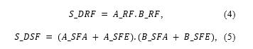 where S_DF is a dangerous fault of SRS (top event), S_DRF is the dangerous random failure of SRS, S_DSF is the dangerous systematic failure of SRS, A_RF (B_RF) is a random fault of unit A (B), A_SFE (B_SFE) is a systematic failure of the application software of unit A (B), A_SFE (B_SFE) is a systematic failure of the embedded software or hardware of unit A (B).
The logical function (3) expresses the fact that SRS dangerous failure can be caused by the random or systematic failure.
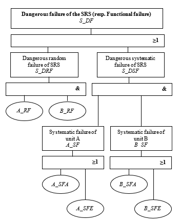 Figure 3: Fault tree for SRS in Figure 2
2.1. The influence of random failures on SF safety integrity
The primary construction elements of PLCs are the electronic components, which are characterized by the occurrence of the random failures. It is generally accepted that the occurrence of random failures of electronic components can be described by the exponential distribution rule. Manufacturers usually declare the failures rates for individual modules (in the case of sPLC, the dangerous failures rate). Based on this information and knowledge of the structure of SRS, the dangerous failures rate of SRS (dangerous failure rate of SF) can be calculated.
If the manufacturer declares the dangerous failure rate for the electronic system or its part (for example, the sPLC module for the implementation of SF with SIL 3), which is designed for industrial applications, then calculating the dangerous failure rate accept to assume that every second failure either alone or in combination with another failure (other failures) is dangerous [7]. Such an assumption may not be in accordance with the requirements for other applications. For example, for railway applications [6], if SIL 4 is required for an SF that is implemented with an electronic SRS, then it is considered that any failure may be potentially dangerous. This fact must be taken into account when calculating the failure rate of SF for a specific application.
If the units A and B are physically independent of each other, then the basic events A_RF and B_RF from the fault tree in Figure 3 are independent too. The probability of the dangerous random failure of the SRS can be expressed by relation 6:
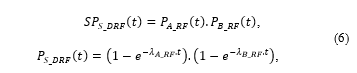 where the is the probability of dangerous random failure of SRS, is the probability of dangerous random failure of unit A, is the probability of dangerous random failure of unit B, is the dangerous random failures rate of unit A (B).
The dangerous random failure rate of SRS can be calculated using the equation:
 after substituting (6) into (7) and adjusting, it can be determined that:
 Assuming that and , then the SRS dangerous failure rate is:
![]() The mutual physical independence of unit A and unit B can be achieved by applying appropriate technical measures (e.g.: galvanic separation of the units, separate the power supply of unit A and unit B, …).
The mutual physical independence of unit A and unit B can be achieved by applying appropriate technical measures (e.g.: galvanic separation of the units, separate the power supply of unit A and unit B, …).
SRS consists not only of sPLC, but also other elements necessary for obtaining information from the monitored (or controlled) process (equipment, machine) and elements for the realization of SF outputs. An example of a frequently used SRS wiring with sensors (SA, SB) and contactors (CA, CB) represents the Figure 4. Safe disconnection of the EUC from the power supply after affecting the sensors is the purpose of this wiring.
The wiring of sensors and contactors follows the sPLC manufacturer’s recommendations and their selection depends on the specific application. In this case, contactors are used which, in addition to the coil (WA, WB) and the main contacts (c1A, c1B), also contain control contacts (c2A, c2B). The manufacturer must guarantee the co-operation of the main contact and the mechanically coupled auxiliary contact (it is the characteristic of relay type C according to [8]). The correct function of the contactor is checked using feedback through application diagnostics. The feedback data is compared with the commands for the contactor in the application software. Test diagnostics in the application software and comparison of feedback data are discussed in more detail, e.g. [9] and [10]. Diagnostics can be performed in distinct forms and can cover a whole system [11], [12] or be specifically oriented on selected system parts [13], [14].
 Figure 4: Wiring of the SRS
Occurrence of the dangerous failure due to random failure of SRS in Figure 4 can be described by a fault tree (Figure 5).
If the basic events of the fault tree in Figure 5 are independent (realistic and feasible assumption) then according to (9) it is valid that:
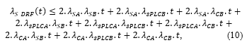 whereas:
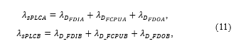 where λSA (λSB) is the sensor A (B) random failure rate, λsPLCA (λsPLCB) is dangerous random failure rate of sPLCA (sPLCB), λCA (λCB ) is random failure rate of the contactor A (B), λD_FDIA (λD_FDIB) is the module F-DI random failure rate of the unit A (B), λD_FCPUA (λD_FCPUB) is the module F-CPU random failure rate of the unit A (B), λD_FDOA (λD_FDOB) is the module F-DO random failure rate of the unit A (B).
 Figure 5: The fault tree of the SRS from Figure 4
If the SF realized by SRS (Figure 4) is to meet the RanF-SI requirement for SIL 4, then it must be true that
![]() It follows from (10) and (12) that
It follows from (10) and (12) that
 where is the maximum allowed time of failure detection and negation.
2.2. Results of modeling the impact of random failures on the SF safety integrity – a case study
Let the SRS in Figure 4 implements one SF, in the implementation of which all elements participate. The failures rate, or dangerous failures rate of these elements are listed in the Table 1. Figure 6 shows the dependence of the SRS dangerous random failures rate (λS_DRF (t)) depending on the time of failure detection and negation ( ) calculated according to the relation (9) – curve 1 and calculated according to the relation (8) – curve 2. Maximum tolerable dangerous failure rate for SIL 4 is shown by a horizontal line. The intersection of curve 1 or 2 with this line determines the maximum allowed time of fault detection and negation. For curve 1 it means the time 3830 h and 3845 h for curve 2. The difference between determined times is relatively small and acceptable from a safety point of view because the time determined from the simplified relationship (9) is shorter.
Table 1: The failures rates and dangerous failures rates of realized SF
| Element | Failure rate | Dangerous failure rate |
| SA | 5.10-7 h-1 | |
| SB | 5.10-7 h-1 | |
| sPLCA | 4.10-9 h-1 | |
| F-DI 16x24VDC | 1.10-9 h-1 | |
| F-CPU 1516F-3PN/DP | 1.10-9 h-1 | |
| F-DQ 8x24VDC/2A PPM | 2.10-9 h-1 | |
| sPLCB | 4.10-9 h-1 | |
| F-DI 16x24VDC | 1.10-9 h-1 | |
| F-CPU 1516F-3PN/DP | 1.10-9 h-1 | |
| F-DQ 8x24VDC/2A PPM | 2.10-9 h-1 | |
| CA | 6,4.10-7 h-1 | |
| CB | 6,4.10-7 h-1 |
The diagnostic mechanisms available to the SRS must guarantee that all potentially dangerous faults are detectable (diagnostic coverage DC = 100%). Another approach must be used to calculate the dangerous failure rate of SRS if this condition is not fulfilled – for example, a model based on the Markov chain [15] (in this paper, the fault tree analysis (FTA) is used). The issue of using different methods to assess the dangerous failure rate of SRS as well as considering the influence of other factors (besides the random failures rates and DC) on the dangerous failure rate of SRS is discussed in [15]. For the sake of clarity, the fault tree analysis (FTA) method is used in this article.
It can be stated that the realization of SF with SIL 4, with respect to RanF-SI, using a dual structure is realistically achievable.
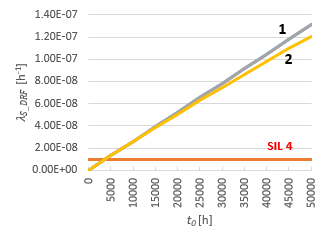 Figure 6: Dependence of the SRS dangerous random failures rate on the failure time detection and negation
2.3. The impact of systematic failures on the safety integrity of SF
While RanF-SI is a quantifiable part of SI, SysF-SI is a non-quantifiable part of SI. Probability calculations cannot be used for its evaluation (assessment), because the rate of the occurrence of the systematic failures is not known (practically, the occurrence of systematic failures is impossible to identify) and the distribution of systematic failures is not known. Achieving the required
SysF-SI is based on the effective prevention of failures by applying appropriate and suitable safety measures (depending on the required SIL for SF), which are defined in the relevant standards for the given areas of applications. The evaluation (assessment) of SysF-SI is based on the assessment that the prescribed safety measures are effective and have been applied at a sufficient level [2].
The fault tree in Figure 3 shows the influence of systematic failure on the occurrence of the SRS dangerous failure. This influence is expressed by a logical function (5). In general, it should be assumed that unit A and unit B have only some mutual systematic failures, and thus it cannot be valid that the basic events A_SF, B_SF are mutually interdependent. Therefore, in this case, it must be evaluated by the general relation that:
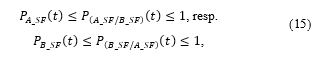
 where is the probability of dangerous systematic failure of the SRS, ( ) is the probability of systematic failure of unit A (B), is the conditional probability of systematic failure of unit B provided that the systematic failure of unit A has occurred and is the conditional probability of systematic failure of unit A provided that the systematic failure of unit B has occurred.
In general, it is valid that
 where , resp. , if the units A, B are identical (have the same systematic failures) and , resp. , if unit A and unit B are mutually independent (units do not have the same systematic failures).
Figure 7 shows in principle the influence of safety measures to prevent of systematic failures in consideration of the degree of interdependence of units A, B and therefore also to the on SI.
If the units A and B are HW and also SW identical (same sPLC and the same application software; Figure 7a), then it can be stated that the units A, B are dependent and the SF, which is realized by these units has the same level of SysF-IS as would have SF if it were realized only by one unit (unit A or unit B). This means that if the sPLC manufacturer states that using this sPLC can be realized SF with max. SIL 3, it must be assumed that the SysF-IS level is 3. The fact is that in such a case it does not make sense to use a dual structure.
Increasing the SysF-IS level can be in principle achieved in the following ways (safety measures):
 Figure 7: The illustration of the “overlapping” of the sets of systematic failures of unit A and unit B
- software diversification (different software in unit A and in unit B);
- hardware diversification (different hardware in unit A and in unit B, i.e. using of different sPLCs in unit A and in unit B);
- diversification of hardware and software.
Modifying the embedded software is a very effective safety measure to increase the SysF-IS level. However, when using sPLC, such a solution is practically impossible because this software is inaccessible to the user (this is information that the sPLC manufacturer does not provide). Diversification of application software is possible. In addition to functional algorithms related to the realized SFs, the application software can also implement mechanisms that allow the detection of a part of the systematic failures operating in a given unit. These are, for example, the following mechanisms:
- a clear, complete, and verifiable specification of requirements;
- registration of requirements using semi-formal or formal methods;
- compliance with coding standards;
- use of verified function blocks that are verified by “good” practice;
- consistent testing.
The fact is that the number of reduced systematic failures can be expected, but it cannot be demonstrated that the level of remaining systematic failures is acceptable. This is also related to the fact that the set of systematic failures is not known and therefore it is impossible to implement safety measures for their detection and subsequent negation in a targeted manner. In reality, some safety mechanisms implemented in application software may be redundant.
The aim of diversification is not to reduce the number of systematic failures in unit A, resp. unit B, but the goal is to minimize the mutual dependence (Figure 7b). This minimization is achieved by the fact that existing systematic failures do not affect the data manipulated in these units in the same way and at the same time (by acquiring or processing or transforming or storing or transmitting data). In association with diversification, it should be noted that a powerful diagnostic tool in the dual structure presented here is the comparison of data. The larger volume of data that is the subject of the comparison and the frequency of comparison make a greater probability of detecting a failure. Diversification brings the problems of ensuring the compatibility of different sPLCs and with the synchronization requirement to be comparison possible at all. Comparison of output signals only is not considered sufficient.
The ideal situation is shown in Figure 7c, when the interpenetration of systematic failures of unit A and unit B is zero.
3. Conclusion
The use of sPLCs in dual architecture (certified to SIL 3) primarily eliminates random hardware failures. In this way, it is possible to achieve the final SIL of the realized safety functions at level 4.
Fight against the systematic failures can be done best at the embedded software level. Due to the fact that the embedded software is fixed from the user’s point of view, the use of sPLC from two different manufacturers and the subsequent application of discrepancy diagnostics may be a suitable solution. Discrepancy diagnostics must be focused on a thorough comparison of internal states, memory states, etc.
Manufacturers of the sPLCs certified to SIL 4 are already starting to appear (e.g. HIMatrix product from the HIMA Company [16]). However, such products are rare and their use is precisely limited to a particular area of application. It can be assumed that in the future, the development of sPLCs will be aimed at increasing their safety and expanding their application possibilities.
Conflict of Interest
The authors declare no conflict of interest.
Acknowledgment
This work has been supported by the Educational Grant Agency of the Slovak Republic (KEGA) Number 008ŽU-4/2019: Modernization and expansion of educational possibilities in the field of safe controlling of industrial processes using the safety PLC.
- K. Rástočný, J. Ždánsky, J. Hrbček, “The problems related to realization of safety function with SIL4 Using PLC,” in Proceedings of the 30th International Conference on Cybernetics and Informatics, K and I 2020, Institute of Electrical and Electronics Engineers Inc., 2020, doi:10.1109/KI48306.2020.9039878.
- EN 61508 – European Standards, Functional Safety of Electrical/ Electronic/Programmable Electronic Safety-Related Systems, 2010.
- 1sig – Zabezpečovací systémy pro železnice, tramvaje a metro, První Signální, a.s., Jan. 2021.
- Schneider Electric – Orbus Hardwired Safety Systems, Schneider Electric Global, Jan. 2021.
- Pilz – Automation solution in the railway industry, Pilz GmbH & Co. KG, Jan. 2021.
- EN 50129 – European Standards, Railway Application. Communication, Signalling and Processing Systems. Safety-Related Electronic Systems for Signalling, 2018.
- EN 62061 – European Standards, Safety of Machinery – Functional Safety of Safety-Related Electrical, Electronic and Programmable Electronic Control Systems, 2016.
- EN 50578 – European Standards, Railways Applications. Direct Current Signalling Relays, 2013.
- J. Ždánsky, K. Rástočny, J. Hrbček, “Influence of architecture and diagnostic to the safety integrity of SRECS output part,” International Conference on Applied Electronics, 2015-Octob, 297–301, 2015.
- K. Rástočný, J. Ždánsky, J. Balák, P. Holečko, “Diagnostics of an output interface of a safety-related system with safety PLC,” Electrical Engineering, 99(4), 1169–1178, 2017, doi:10.1007/s00202-017-0624-1.
- A.H. Naghshbandy, H.M. Shanechi, A. Kazemi, I. Pourfar, “Study of fault location effect on the inter-area oscillations in stressed power systems using modal series method,” Electrical Engineering, 92(1), 17–26, 2010, doi:10.1007/s00202-010-0154-6.
- W. Velten-Philipp, M.J. Houtermans, “The effect of diagnostic and periodic proof testing on the availability of programmable safety systems,” WSEAS Transactions on Systems, 5(8), 1861–1867, 2006.
- J.C. Urresty, J.R. Riba, L. Romeral, J.A. Ortega, “Mixed resistive unbalance and winding inter-turn faults model of permanent magnet synchronous motors,” Electrical Engineering, 97(1), 75–85, 2014, doi:10.1007/s00202-014-0316-z.
- M. Moujahed, H. Ben Azza, K. Frifita, M. Jemli, M. Boussak, “Fault detection and fault-tolerant control of power converter fed PMSM,” Electrical Engineering, 98(2), 121–131, 2016, doi:10.1007/s00202-015-0350-5.
- K. Rástočný, J. Ždánsky, M. Franeková, I. Zolotová, “Modelling of diagnostics influence on control system safety,” Computing and Informatics, 37(2), 457–475, 2018, doi:10.4149/cai_2018_2_457.
- HIMatrix – The Compact Safety Solution, HIMA Paul Hildebrandt GmbH, Jan. 2021.