Modeling and Design of a Compact Metal Mountable Dual-band UHF RFID Tag Antenna with Open Bent Stub Feed for Transport and Logistics Fields
 , Aarti Bansal 3, Mohsine Bouya 2, Azeddine Wahbi 4, Antonio Lazaro 5, Abdelkader Hadjoudja 1
Adv. Sci. Technol. Eng. Syst. J. 6(1), 1065–1071 (2021);
 DOI: 10.25046/aj0601118
In this paper, we have modeled and designed a metal mountable tag antenna that is applied to cover two major UHF RFID bands, i.e., European (EU) (865-867 MHz) and U.S. bands (902-928 MHz). It is applied for many applications, especially in the transport and logistics fields. The tag antenna configuration utilizes microstrip configuration with open bent stub feed network to attain conjugate matching w.r.t. Monza R6 chip impedance. The proposed microstrip patch-based tag antenna structure is simple without using any shorting pin/holes, thus making it easy and inexpensive to manufacture. Additionally, the proposed tag’s impedance has been easily tuned in order to achieve conjugate matching in regard to the employed chip impedance. The presented tag antenna has been fabricated and experimentally characterized to measure its read-range performance in the desired bands. Further, the differential probe set up is used to measure the designed tag’s impedance. Also, the designed tag read-range is measured using a reader setup and is observed to exhibit read-range up to 11 m and 9 m in European and U.S. UHF RFID bands, respectively. The tag exhibits an impedance of 9.7 – j 130 ohms at 866 MHz and 8.7 – j 124 ohms at 915 MHz. The proposed tag antenna design’s performance is verified, analyzed, and optimized by CST Studio Suite software. The performances of the designed tag are evaluated and analyzed in terms of conjugate matching, reflection coefficient, and read range measurement. From the results, it is noticed that the designed tag exhibit dual-band behavior with good impedance matching, Reflection coefficient, and high read range.
1.Introduction
Ultra-High Radio Frequency Identification (UHF-RFID) technology has emerged as an efficient technique to track the objects/items/products without needing to be in the line of sight. The major RFID applications are in access control, logistics, healthcare, asset tracking owing to its advantage of long read range and compact size in comparison to Low (L.F.) and High Frequency (H.F.) bands [1]. The UHF RFID band is further divided between two major regions, i.e., European and North America/U.S. covering (865-867 MHz) and (902-928 MHz) bandwidth with a maximum allowed transmitted power of 3.28 W and 4 W, respectively [2], [3]. To operate the tag reliably in both the regions, it is required that the designed tag must exhibit dual-band operation covering European and U.S. UHF RFID bandwidth.
The RFID tag has to be affixed on a different type of conductive and non-conductive object to be tracked. Further, the performance of the tag deteriorates significantly especially when placed on conductive items such as metals. This is attributed to the cancellation of radiations resulting from phase electromagnetic wave reflections from the underlying metal surfaces [4-6]. To track the metallic objects efficiently, some of the recent work utilizes a microstrip patch antenna with a full ground beneath to overcome the influence of conductive objects such as metal, liquids, etc. as depicted in ref [7] and [8]. Further, the planar inverted-F antenna (PIFA) incorporating vias/ holes for the compact-sized tag is presented in [9], [10]. However, the employed vias/holes contribute to increased fabrication cost and complexity to the tag structure.
In this article, the work presented in [11] is extended further. Here, a dual-band metal mountable tag antenna having a planar structure covering European and North American UHF RFID bands is designed. The proposed tag antenna utilizes a microstrip patch antenna having a bent open stub feed. This bent feed structure offers the benefit of easy impedance tuning of the designed tag considering the complex chip impedance.
In this paper, we propose an RFID tag antenna to be integrated to track items in fundamental applications such as in the supply chain for the transport and logistics field. Effective management of this chain leads to very concrete results. To increase this efficiency, the implementation of an RFID based container-tracking system is necessary. This will contribute to real-time identification and reaching new levels of traceability and control.
To that end, and to test the performances of the UHF RFID tag developed, a real test is planned on the metal containers in airports; this test requires the deployment of a chain of readers and tags attached to the objects.
The container is the basic loading unit, usually made of aluminum alloys, with different sizes, the largest, exclusively on cargo aircraft, and the means are loaded in the holds of passenger aircraft.
For better optimization of airfreight, goods are transported in containers designed for safety reasons and to facilitate loading and unloading operations. These goods can be easily tracked using a metal mountable RFID tag. Thus, in this article, a UHF RFID tag is proposed, designed and tested for metallic objects. The designed tag is able to operate on two frequency bands EU and US to ensure interoperability of the system. This work is an extension of the work presented in [11], In this paper, the designed tag antenna’s working performance on the basis of circuit analysis is represented. Further the simulated results of the tag presented in [11] are verified experimentally in terms of differential impedance and read range. Also, the designed tag’s read range performance is compared for two different heights of the substrate. It is observed from a comparison table (Table II) that the designed tag has better performance with respect to other recently designed tags covering two major RFID bands at UHF range i.e., ETSI and U.S. Further, the tag is specifically designed for metal mountable applications. Also, the designed tag covers a better-measured read range of 11 m and 9.7 m in ETSI and U.S. band when mounted on metal objects.
The paper is organized as follows. The proposed tag antenna structure is introduced in Section 2. The section 3 discusses the equivalent circuit of the patch antenna. The parametric study to show its tuning capability for conjugate impedance matching is shown in Section 4. Further, the simulation performance of the designed tag antenna is shown in Section 5. The impedance measurements for the employed RFID chip i.e. Monza R6, and the designed tag antenna is carried out in Section 6. Also, Section 7, presents the designed tag’s measured read range performance. Finally, Section 8 concludes the work.
2. Proposed design
2.1. Antenna structure
The tag antenna proposed here has been designed using a microstrip patch antenna. The proposed tag antenna geometry and its dimensions are illustrated in Fig.1 and Table 1, respectively as described in [11]. It consists of two simple microstrips, a patch, and a bent feed line [8].
 Figure 1: The proposed tag antenna design (Top View and Side view).
Table 1: The proposed antenna dimensions (units in mm)
| Par. | L | W | Lp | Wp | Lr1 | Li | Lr2 | Wr2 |
| Value | 85 | 40 | 42 | 30 | 30 | 25 | 36 | 11 |
The tag structure is designed with a full ground plane beneath to be mountable on metallic objects. It is fabricated using FR4 substrate having εr = 4.69, tan δ = 0.02, and a thickness h=3.2 mm, with a total dimension of W*L (40 mm * 85 mm). As the size is a critical factor in designing RFID tags, and in order to reduce tag size, the bent feed line structure has been adopted for feeding the patch. The antenna size can also be reduced by opting for higher permittivity substrates. However, they lead to higher costs. Also, the open stub feed line inserted into the patch decreases the input impedance of the patch. The RFID chip is connected to the feed line and its position is optimized to obtain conjugate impedance matching. The parameters L1 and Lr1 are optimized to obtain conjugate matching.
3. Equivalent Circuit Model
Figure 2 illustrates the transmission line model of the designed antenna. From the figure, the global structure of the antenna model has been modeled as two transmission lines connected in series configuration [12] comprising of microstrip patch and the feed line of lengths and respectively. The antenna input impedance at the feed port can be calculated as:
![]() where represents the input impedance of the radiation patch, and represents the input impedance of the bent open stub line.
where represents the input impedance of the radiation patch, and represents the input impedance of the bent open stub line.
Further, the microstrip patch input impedance is given as in [13]:
![]() where , and are the resistance and characteristic impedance and the propagation constant of the radiation patch.
where , and are the resistance and characteristic impedance and the propagation constant of the radiation patch.
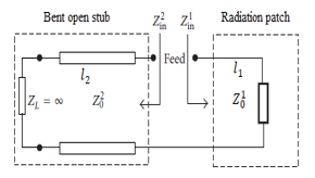 Figure 2: Open stub patch antenna transmission line model representation
Also, the employed open stub feed’s input impedance is represented by:
![]() where the characteristic impedance of the open stub line is represented by .
where the characteristic impedance of the open stub line is represented by .
For a preliminary design of the radiating patch antenna, and before proceeding with the optimization, the dimensions were calculated using the classic rectangular patch equations expressed bellow:
![]() where L is the physical length, Δ? is the extended length due to fringing field effects and ???? is its effective length. The extended length, Δ? is given by [14] as shown in equation (5).
where L is the physical length, Δ? is the extended length due to fringing field effects and ???? is its effective length. The extended length, Δ? is given by [14] as shown in equation (5).
![]() where is the width of the patch, ℎ is the substrate height, and ???? is the effective dielectric constant.
where is the width of the patch, ℎ is the substrate height, and ???? is the effective dielectric constant.
Also, the effective dielectric constant of the patch is represented as follows:
![]() where, is the relative dielectric constant of the substrate.
where, is the relative dielectric constant of the substrate.
4. Parametric Study
The conjugate impedance matching is optimized by tuning the lengths of the stub, i.e., Li and Lr1, respectively as explained in [11].
Further, the parametric study to investigate the influence of varying the antenna dimensions, i.e., Lr2 and Wr2 in order to tune the second resonant frequency, i.e., 915 MHz, is shown in Fig. 3.
It has been observed that the resonance shifts towards the right by varying these parameters simultaneously and keeping the other parameters constant.
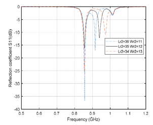 Figure 3: Simulated reflection coefficient versus frequency of the for different values of Lr2 and Wr2.
5. Simulation results
In this context, we have designed, analyzed, simulated, and optimized the proposed tag antenna using CST Studio Suite software.
The tag antenna must exhibit conjugate impedance that matches the employed chip impedance, i.e., Impinj Monza R6 [15]. The simulated and measured S11 results for the designed tag antenna are shown in Fig. 4.
 Figure 4: Antenna measured reflection coefficient comparison
6. Impedance Measurement of Designed Tag Antenna and Chip
The Monza R6 chip is employed here at the feeding port of the designed tag antenna and its equivalent circuit is shown in Fig. 3. The chip has a resistance, Rp, of 1200 Ω in parallel to the capacitance, Cp, of 1.43 pF and a chip sensitivity of -20 dBm. The equivalent circuit values for the chip are provided in the datasheet for the die chip and do not take into account the parasitic impedance that includes substrate, packaging, and input power dependence. The packaged chip, i.e., LXMS21ACMF-183 from Murata is used in the designed tag prototypes. Thus, it is important to consider the chip impedance dependence with respect to frequency.
 Figure. 5: Tag Chip Linearized R.F. Model
The measurements of the tag antenna and the chip impedances are obtained using vector network analyzer E5062A from Agilent. The tag antenna impedance cannot be directly measured using a 50 Ohms port directly. Therefore, to measure the differential impedance, the tag antenna has been considered as a two-port network and to measure its reflection coefficient, its differential impedance input impedance, Zin, has been calculated represented as:
![]() here, Z0 represents the coaxial cable’s characteristic impedance. Figure 6 illustrates the setup to measure the impedance. The differential balun with short-circuited semi-rigid coaxial cables using λ/4 was constructed to measure the impedance. The terminals of constructed balun are soldered to the feed terminals of the designed tag antenna Further, the port extension technique has been applied while measuring differential impedance as detailed in [16].
here, Z0 represents the coaxial cable’s characteristic impedance. Figure 6 illustrates the setup to measure the impedance. The differential balun with short-circuited semi-rigid coaxial cables using λ/4 was constructed to measure the impedance. The terminals of constructed balun are soldered to the feed terminals of the designed tag antenna Further, the port extension technique has been applied while measuring differential impedance as detailed in [16].
 Figure 6: Equipment for chip and antenna characterization. (a) VNA, (b) Balun
Figure 7 and fig. 8 shows the used chip input impedance measurements versus the frequency. The chip impedance is measured to be 9.7 – j 130 Ω at 866 MHz and 8.7 – j 124 Ω at 915 MHz, respectively. In comparison, the input impedances given in the datasheet are 13.6-j 127 Ω at 866 MHz and 12.2-j 120 Ω at 915 MHz [17]. As observed, the packaged chip input impedance is slightly different and also depends on the input power.
Finally, the reflection coefficient (Г) is further calculated using measured tag antenna impedance i.e., Zin and chip impedance, i.e., Zchip respectively, and is represented as:
![]()
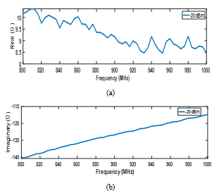 Figure 7: Chip input impedance for -20 dBm input power
 Figure 8: Representation of simulated and measured results of the antenna input impedance
Figure 9 shows a comparison of the simulated and measured reflection coefficient results in the 2 required frequency bands i.e. ETSI & FCC.
 Figure 9: Results of the antenna’s reflection coefficient.
It can be seen that a reasonably good value for the reflection coefficient is obtained, which validates the existence of a suitable conjugate impedance matching between the chip’ and the designed tag antenna impedance.
7. Read Range Measurements
The reading range or the tag range is defined as the maximum distance from which the tag can be recognized [18], and is the most important parameter for evaluating the RFID tag performance. The equation below shows this reading range following the Friis formula for free space:

where PEIRP is the equivalent isotropic radiated power specified as 3.3 W in the E.U. band and 4 W in the U.S. band.
Further, λ represents the operating free-space wavelength and Pth indicates the chip sensitivity at the resonant frequency. The Gtag is defined as the antenna tag’s gain and Г is the reflection coefficient defined above in equation (8). The tag’s read range can be maximized by achieving a lower-power reflection coefficient defined by |Г|2 and a high-gain antenna Gtag.
Also, the ability of the tag to transfer power to the connected chip is represented by (1-|Г|2) which is also known as the power transmission coefficient of the tag.
Figure 10 describes the devices used for experimental measurement of the reading range in an anechoic chamber.
 Figure 10: The Read range measurement setup
The measuring setup consists of an RFID reader, i.e., CAEN RFID, circularly polarized Reader antenna with a realized gain Gr of 8 dBi. The reader is connected to the reader antenna and a host computer. The cable losses and attenuator losses were taken into consideration.
From the measurement results, we deduced that the tag has a reading range of approximately 11 m and 9.7 m at 866 MHz and 915 MHz with an EIRP of 3.3 W, respectively, as illustrated in Fig. 11.
The gain of the tag antenna, as well as the height of the chosen substrate, strongly influences the read range of the tag. a comparison of the read range for two different substrate heights i.e., 3.2 and 1.6 is shown in Figure 12. The read distance was observed to degrade from 11m to 4 m at 866 MHz and 9.7 m to 3.7 m at 915 MHz.
 Figure 11: Results of simulated and measured antenna read range
 Figure 12: Read-range for two different substrate thickness.
7.1. 3D-Radiation Pattern
As already mentioned, impedance matching between antenna and chip impedances, is a key design requirement. Therefore, its radiation pattern cannot be measured directly using a 50-ohm port. Hence, the performance of the tag antenna is also assessed based on its simulated 3 D (Dimensional) gain and radiation pattern as shown in Figure 13. It has been observed from the figure that the tag antenna exhibits a realized gain of -3 dBi. Also, to minimize the effect of mounted objects, the tag should exhibit a unidirectional radiation pattern. Thus, it is depicted from Fig. 14, that the designed tag antenna exhibits a directional radiation pattern with a directivity of 4.2 dBi. This feature is mainly desirable to design the platform tolerant tag and hence validates its application for metal mountable tracking objects.
A performance comparison of our proposed tag antenna with some previous research studies representing metal-mountable UHF RFID tags is shown in Table 2. From the table, it has been observed that the tags designed in [18-22] are larger as compared to the tag proposed in this work. Moreover, our proposed tag is characterized by its operability in the two main frequency bands with a better reading range. On the other hand, all the other tags shown in the table cover a single UHF RFID band. Further, the tag designed in [20] is compact, however, still it covers a lower read range in a single UHF RFID band.
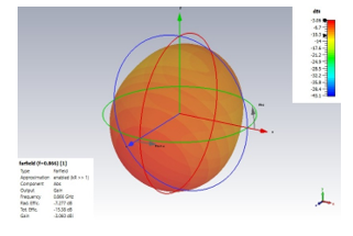 Figure 13: 3 D Gain pattern of the designed tag at 866 MHz
 Figure 14: 3 D directivity pattern of the designed tag at 866 MHz
Table 2: A comparison table performances of UHF tags mounted on metallic items
| Ref. | Transmitting
EIRP Power |
Circuit Size
(mm) |
Backing Plate
Size (cm) |
Max. Read
Range (m) |
| This work | 4 W | 85×40×3.2 | 20×20 | 11 m (ETSI)
9.7 m (FCC) |
| [19] | 4 W | 86×41×3.2 | 20×20 | 5.6
|
| [20] | 3.3 W | 88×60×0.76 | 15×15 | 5.4 |
| [21] | 4 W | 30×30×3 | 20×20 | 7.2 |
| [22] | 4 W | 120×60×0.4 | 15 × 30 | 10 |
| [23] | N/A | 84×126×1.28 | N/A | 2.5 |
Thus, better performances in regard to reading range, size and also covered bands, characterize our proposed RFID tag. Also, it is deduced that the designed tag may be employed for different applications such as health monitoring, logistics, and transport supply chains, and IoT (Internet of Things) network applications, etc.
8. Conclusion
In this research paper, a new planar dual-band compact platform tolerant UHF RFID tag antenna presented in [11] has been simulated, fabricated, and tested for its impedance and read range performance experimentally. To measure the real performance of metallic objects, the tag is mounted on a metal sheet. (20 m x 20 m) while measuring. Our tag antenna is modeled and designed using CST Studio Suite software. The designed tag is specifically designed to be mountable on metallic items by considering a full ground plane. The tag comprises a simple structure and does not include any vias, thus facilitating low-cost, efficient design for mass production. Further, the simulated and measured impedance, reflection coefficient, and read ranges of the tag structure have been presented and are observed to be well in agreement with each other. From the tag antenna reflection coefficient, it is realized that the designed antenna covers both major UHF RFID bands i.e., European (E.U., 865-867 MHz) and North American (the U.S., 902-928 MHz). The designed tag exhibits a read range up to 11 m at 866 MHz and 9 m at 915 MHz.
Hence, the designed tag antenna is observed to perform better in terms of conjugate impedance matching, unidirectional radiation pattern, and high read range in both the required resonant bands. Thus, it is validated that the designed tag is suitable for use in real-time applications such as transport and logistics fields and IoT network applications.
Conflict of Interest
The authors declare no conflict of interest.
Acknowledgment
The authors would like to thank MESRSFC and CNRST for the financial support.
- K. Finkenzeller, RFJD handbook, 3rd ed Wiley, New York, 2010
- I. Any et al., “Regulatory status for using RFID in the EPC Gen2 ( 860 to 960 MHz ) band of the UHF spectrum,” 2(November), 1–18, 2016.
- V. D. Hunt, A. Puglia, and M. Puglia, RFID: A Guide to Radio Frequency Identification. New York: Wiley, 2007.
- T. Björninen, L. Sydänheimo, L. Ukkonen, and Y. Rahmat-Samii, “Advances in antenna designs for UHF RFID tags mountable on conductive items,” IEEE Antennas Propagation Magazine, 56(1), 79–103, 2014. doi: 10.1109/MAP.2014.6821761.
- D. M. Dobkin, S. M. Weigand, W. J. Communications, and S. Jose, “Environmental Effects on RFID Tag Antennas,” 135–138, 2005.
- K. Penttilä, M. Keskilammi, L. Sydänheimo, and M. Kivikoski, “Radio frequency technology for automated manufacturing and logistics control. Part 2: RFID antenna utilization in industrial applications,” The International Journal of Advanced Manufacturing Technology, 31(1–2), 116–124, 2006. doi.: 10.1007/s00170-005-0174-y
- H. Chen, S. Member, C. Sim, and S. Kuo, “Compact Broadband Dual Coupling-Feed Circularly Polarized RFID Microstrip Tag Antenna Mountable on Metallic Surface,” IEEE Transaction Antennas and Propagation, 60(12), 571–5577, 2012. doi: 10.1109/TAP.2012.2210273.
- L. Mo and C. Qin, “Planar UHF RFID Tag Antenna With Open Stub Feed for Metallic Objects,” IEEE Transaction Antennas and Propagation, 58(9),3037–3043, 2010. doi: 10.1109/TAP.2010.2052570
- M. Hirvonen, P. Pursula, K. Jaakkola, and K. Laukkanen, “Planar inverted-F antenna for radio frequency identification,” ELECTRONIC LETTERS, 40 (14), 2004. doi: 10.1049/el:20045156
- H. Chen, S. Member, and Y. Tsao, “Low-Profile PIFA Array Antennas for UHF Band RFID Tags Mountable on Metallic Objects,” IEEE Transaction Antennas and Propagation, 58(4), 1087–1092, 2010. doi: 10.1109/TAP.2010.2041158
- H. Bouazza, A. Lazaro, M. Bouya and A. Hadjoudja, “Dual-band UHF RFID tag for metallic items,” 2019 IEEE-APS Topical Conference on Antennas and Propagation in Wireless Communications (APWC), 090-092, 2019, doi: 10.1109/APWC.2019.8870474.
- L. Mo and C. Qin, “Tunable compact UHF RFID metal tag based on cpw open stub feed PIFA antenna,” International Journal of Antennas and Propagation 2012. doi: 10.1155/2012/167658
- L. Reinhold and B. Pavel, RF Circuit Design: Theory and Applications. New York: Pearson Education, 2000. doi: 10.1155/2012/167658
- C. A. Balanis, Antenna Theory Analysis and Design, 3rd ed. New Jersey: John Wiley & Sons, 2005.
- Datasheet Impinj Monza R6, https://support.impinj.com/hc/en-us/articles/202765328-Monza-R6-Product-Brief-Datasheet
- A. Bansal, S. Sharma, Khanna, “platform tolerant dual-band UHF RFID tag antenna with enhanced read range using artificial magnetic conductor structures”. Int. J RF Microw Comput Aided Eng. 2019. doi: 10.1002/mmce.22065
- H. Bouazza, A. Lazaro, M. Bouya, and A. Hadjoudja, “A Planar Dual-Band UHF RFID Tag for Metallic Items”, Radioengineering, 29(3), 505. 2020, doi: 10.13164/re.2020.0504
- A. Bansal, S. Sharma and R. Khanna, “A Spiral Shaped Loop Fed high Read Range Compact Tag Antenna for UHF RFID Applications,” 2019 IEEE International Conference on RFID Technology and Applications (RFID-TA), 212-215, 2019, doi: 10.1109/RFID-TA.2019.8892203.
- A. P. Sohrab, Y. Huang, M. N. Hussein and P. Carter, “A Hybrid UHF RFID Tag Robust to Host Material,” in IEEE Journal of Radio Frequency Identification, 1(2), 163-169, June 2017, doi: 10.1109/JRFID.2017.2765623.
- POLIVKA, M., SVANDA, M. “Stepped impedance coupled patches tag antenna for platform tolerant UHF RFID applications. IEEE Transactions on Antennas and Propagation”, 63(9), 3791–3797. 2015, doi: 10.1109/TAP.2015.2447034
- F. Bong, E. Lim and F. Lo, “Flexible Folded-Patch Antenna With Serrated Edges for Metal-Mountable UHF RFID Tag,” in IEEE Transactions on Antennas and Propagation, 65(2), 873-877, 2017, doi: 10.1109/TAP.2016.2633903.
- Y. Lin, M. Chang, H. Chen and B. Lai, “Gain Enhancement of Ground Radiation Antenna for RFID Tag Mounted on Metallic Plane,” in IEEE Transactions on Antennas and Propagation, 64(4), 1193-1200, 2016, doi: 10.1109/TAP.2016.2526047.
- M. Abu, E. E. Hussin, A. R. Othman, F. M. Johar, N. M. Yatim, and R. F. Munawar, “Design of 0.92 GHz artificial magnetic conductor for metal object detection in RFID tag application with little sensitivity to incidence of angle,” Journal of Theoretical and Applied Information Technology., 60(2), 307–313, Feb. 2014. Id: 73550079