Formal Proof of Properties of a Syntax-Oriented Editor of Robotic Missions Plans

Adv. Sci. Technol. Eng. Syst. J. 6(1), 1049–1057 (2021);
 DOI: 10.25046/aj0601116
This article copes with the formal verification of properties of the missions building module of PILOT’s software. PILOT is a language dedicated to remote control of robots. An incremental syntax-oriented editor was built in order to increase the dependability of PILOT’s missions and we showed that, under a maximum size of plan, this editor allows building only all plans that are syntactically correct. The limitation in size was due to state space explosion problem inherent to the Model-checking approach used for the proof. In order to extend the proof to all plans without any limitation in size, we investigated the theorem-proving approach, and especially PVS (Prototype Verification System). This paper therefore focuses more on modeling of PILOT plans and related building operations and the use of PVS to verify properties of the built models, in view of proving the aforementioned properties of PILOT software’s missions building module.
1.Introduction
This paper extends the work originally presented in [1]. In the prolongation of preceding works aiming at enhancing the dependability of robotic applications [2-12], it targets the use of verification systems, and especially PVS (Prototype Verification System), for properties verification of a syntax‑oriented editor of missions plans conceived for PILOT, a programming language devoted to the control of robots from remote. PILOT is developed within the Laboratory of Sciences and Techniques of Information, Communication and Knowledge (Lab-STICC). Proof systems rest on methods of formal proof or verification that can be described as approaches enabling to define systems properties and check their correctness using mathematics techniques and inference rules. In an earlier work, with the help of Prolog and University of Amsterdam’s SWI-Prolog tool, we proved that the syntax‑oriented editor allows building all and only plans having a correct syntax. Nevertheless, we could only do this proof for plans whose size was under a maximum limit, due to the explosion of state-space inherent to the model‑checking approach implemented using the SWI‑Prolog tool. Theorem proving approaches and related tools such PVS should make it possible to get rid of the constraint on plans size, and to extend the proof to all plans whatever their size. PVS has been chosen because of our experiment in its use for protocol verification [13, 14]. The formal verification of properties of PILOT’s syntax‑oriented editor involves a proper formalization of the language syntax and of the editor’s working. This article is dedicated to the modeling of PILOT plans and building operations of plans, and the use of PVS to verify properties of the built models, in view of proving the correctness of PILOT’s incremental syntax-oriented editor.
The rest of this paper is structured as follows. A state of the art of robotic systems’ formal verification is presented in the second section. The third section addresses preliminaries on formal proof methods and gives an overview of PVS. The language PILOT as well as PILOT plans construction and checking method are presented in the fourth section. The fifth section deals with verification of properties with the help of SWI-Prolog tool. The sixth section is dedicated to the modeling of plans and building operations of plans, and verification of properties on the models using PVS. Conclusions are presented in the seventh and last section.
2. Related works
In [15], the authors reminded, firstly that formal methods of verification were only recently introduced in the control community to assist developers in the construction of complex robotic systems’ control architectures, and secondly that the hybrid nature of such systems (combination of discrete and continuous behaviors) makes their formal treatment hard and necessitates new methods that are both operational and efficient.
In [16], the authors tackle issues and outlooks in robotics. One of the issues they pinpoint is long-term mission execution capability. Despite the fact that dependability, formal verification and fault tolerance methods are not directly referred, they are needed to reach that objective.
In [17], the authors address the inclusion of operations into the control architecture of a UUV (unmanned underwater vehicle) for the mapping and the watching of the ocean. The proposed control system integrates safety mechanisms to lessen hazards at the Mission level and necessitates to use formal verification approaches.
In [18], the authors portray an approach for the use of formal tools to verify the controllers of unmanned autonomous vehicles (UAV) working in congested areas. They mention that the design of controllers of such systems is difficult, in consequence of the required speed and responsiveness. They also notify that, since it is costly to test and compare distinct UAV controllers, formal verification is the number one phase for their performance and efficiency optimization.
In [19], the authors propound a model-checking tool for user assistance in properties checking of systems having complex behaviors. The system modeling is done with the help of a finite-state automaton. The latter is very large and its manual verification is therefore very difficult. The model-checking tool helps the user by automating part of the verification process.
In [20], the authors propose a review of research works related to the application of formal specification and verification methods to the autonomous robotic domain. They pinpoint the insufficiency of testing on real deployment or simulation of autonomous robots. Indeed, the complexity of these robotic systems and their use in safety critical applications do not allow to test some of their behaviors. The authors claim the necessity to use formal methods to guarantee the exactness of such systems.
In [21], the authors propose an integration of the modeling language Timed Rebeca in ROS, a middleware for mobile robots’ program development. A conceptual model of ROS programs in Timed Rebeca is proposed and used to verify the correctness of properties defined by users on ROS programs. Timed Rebeca is based on a model checking approach.
In [22], the authors deal with the formal proof of a robotic system. Model checking approach is applied as well as theorem proving approach of higher-order logic. The first one requires the discretization of the differential equations describing the continuous dynamics of the system and therefore limits the model to an abstracted view of the system, whereas the second one allows using it in its true form and makes it possible to take into account all the real possibilities of the dynamics of the system. Different techniques used for the analysis of the robotic system are compared, based on expressiveness, accuracy and automation.
Above works show the usefulness of formal verification approaches in robotics. They also show that solutions and tools are needed to facilitate the use of formal verification methods in the robotic domain. Analysis of state of the art reveals that the majority of works on formal verification of robotic systems use model checking techniques. In [20], only 3 between 49 works related to formal verification of robotic systems use theorem proving, despite their ability to avoid the state-space explosion issue that sometimes occur when using model checking. It is necessary to develop the use of theorem provers for robotic systems, given their complexity that makes their verification with model checkers prone to the state-space explosion problem.
In the next section, preliminaries on formal proof methods are first introduced, then the theorem prover PVS is presented.
3. Preliminaries on formal proof methods and Prototype Verification System
3.1. Formal proof methods
Two main formal proof methods exist: model-checking and demonstration also called theorem proving.
In the model checking approaches (illustration in figure 1), system’s state-space model is built and its properties are first specified. Both are then input to the model checking system that goes through the state space exhaustively and checks if the system satisfies the given properties. When a property is not satisfied, the model checker generates error information.
 Figure 1: Model checking
In the theorem proving approaches (illustration in figure 2), system’s mathematical model is built and its properties are formalized using a well-defined logic. Both are then input to the theorem proving system as theorems. Using axioms, hypothesis and deductive reasoning (inference rules), the theorem prover helps the user to develop his proof and to verify if the system satisfies the given properties. Inference rules together with theorems that have already been verified make it possible to prove new theorems. When the theorem proving relies on a decidable (propositional) logic, it can be automatic. When it is based on an un-decidable (higher-order) logic, it is interactive.
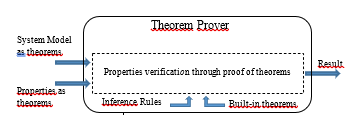 Figure 2: Theorem proving
In comparison to theorem proving, the advantage of model-checking is its entire automation. Its disadvantage is that it is subject to state-space size explosion that could cause problems due to limited computer memory space and limited computational resources.
3.2. Prototype Verification System
PVS [23] is a deductive verification system. It manages a tree of proofs and helps the user to build a full proof tree, i.e. a tree whose terminal nodes are all admitted as being true. Each non-terminal node is a goal from which children nodes are obtained by a step of the proof. Goals are sequents having each the following shape:
p1, p2, …, pn ├ q1, q2, …., qm
where the pi are the antecedents and the qi are the consequents.
PVS system uses backward reasoning: each proof step results in sequents that are at least as strong as previous ones. The root of the proof is the sequent ├ q where q is the theorem to prove.
PVS system furnishes a specification language that is strongly typed [24] as well as an interface that makes it possible to specify systems under Emacs, to formally specify properties on those systems and to prove them with the help of the proof system of PVS [25].
PVS’s specification language is founded upon a logic of higher order. It provides various types and subtypes, including elementary ones (strings, numbers, predicates, etc.), abstract data and compound types (records, union, etc.). PVS system offers several useful functions for the process of formal verification. The main commands implementing the decision procedures are the following:
- typecheck: it makes it possible to analyze the file containing the specification of the system and to detect semantic errors.
- prove: it makes it possible to start the proof of properties that are non-trivial for the system.
- flatten: enables to flatten the structure of the current goal
- split: enables to separate a goal into subgoals
- inst: makes it possible to instantiate variables with given terms
- expand: enables to expand/develop a definition or an expression
- skolem: it makes it possible to “skolemize” quantified variables (quantifiers are removed and quantified variables are replaced by skolem constants).
- grind/ground: enable to launch the process of decision/simplification of a rule.
- induct: makes it possible to perform an induction on a variable.
- undo: enables to go back in the proof.
- lemma: makes it possible to add a lemma to the assumptions.
- More elaborated commands, such as skosimp that iterates the application of skolem and flatten commands on the current rule.
The next section presents the language PILOT and the method of construction and checking of plans.
4. Language PILOT and method of incremental construction and checking of missions’ plans
4.1. The language PILOT
PILOT [5, 26, 27] is founded on the action concept. An action is composed of an order that the robot can execute, a rule of precondition and rules of supervising each having a tied treatment. An action is either elementary or continuous. Elementary actions end by themselves, in general once they reach their goal, while continuous actions’ termination is provoked by a parallel or a preemption primitive. Whether elementary or continuous, an action only executes if its precondition is true. Similarly, when a supervision rule of an action becomes true during its execution, the corresponding treatment is launched. For each supervising rule, the default treatment consists in stopping the related action. Precondition and supervision rules are usually conditions expressed on values of sensors. Figure 3 shows the graphical representation of elementary and continuous actions.
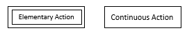 Figure 3: Elementary action and continuous action
In PILOT language, the following control primitives are available for missions’ plans programming:
- Sequentiality: it starts by a “sequence beginning” and ends by a “sequence end”. It enables to define an order of execution on other primitives of the language (actions and control primitives). A graphical symbol named “intersequence” is used to connect the primitives of the sequence. Figure 4 illustrates a sequence comprising 2 elementary actions.
![]() Figure 4: Sequentiality
Figure 4: Sequentiality
- The conditional: it is formed by branches, each composed of a Boolean expression and a sequence following it. Starting from top, the first sequence whose condition is true is the only one to be executed. Figure 5 shows an example of conditional primitive with 2 alternatives.
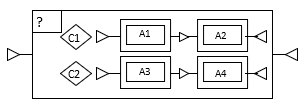 Figure 5: Conditional
- Iteration: it is constituted of a criterion of continuation and a sequence following it. Depending on the continuation criterion, the iteration is said to be fixed or to be conditional. In the first case, the criterion is a number of loops. In the second one, the criterion is a boolean condition. Figure 6 shows and example of fixed iteration on the left and an example of conditional iteration on the right. In the example of fixed iteration, elementary action A1 is executed 3 times. In the example of conditional iteration, elementary action A2 is executed while condition s>2 is true.
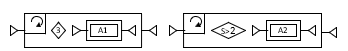 Figure 6: Fixed and conditional iterations
- Parallelism: it is composed of sequences executed in parallel. It terminates its execution when all its sequences have ended theirs. Figure 7 illustrates an example of parallel primitive. In this example, elementary actions A1 and A2 are executed in parallel and the parallel execution ends when both actions reach the end of their execution.
 Figure 7: Parallelism
- Preemption: it is composed of sequences executing in parallel, but unlike parallelism structure, the termination of its execution occurs as soon as one of the sequences ends. Figure 8 illustrates an example of preemption with 2 sequences. In this example, once one of the sequences ends, it causes the termination of the second one and leads to the end of the parallel execution.
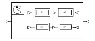 Figure 8: Preemption
After the above presentation of the language PILOT, the next subsection describes the incremental syntax-oriented building approach of missions’ plans.
4.2. Method of construction and checking of PILOT missions’ plans
The syntax-oriented edition of PILOT plans guarantees that the plan is syntactically correct at each step of plan building. When the programmer starts building a mission plan, he obtains a sequence that is empty. In order to continue the construction of the plan, he uses operations insert, erase or modify. The modify operation makes it possible to change elements such as the Boolean expression of a conditional primitive, etc. Whenever an operation is applied by the user, the editor checks the syntactic validity of the plan obtained and only takes the modification into account in the positive case. When the syntax is incorrect, the editor informs the user through a message. For the purpose of ensuring the syntactic correctness of the plan whenever insertion operation is performed, the following default primitives are associated with the structures of PILOT language:
- The default conditional structure which contains a unique alternative consisting in a condition set to “false” followed by an empty sequence.
- The default iteration structure that contains a continuation criterion set to 0 followed by an empty sequence.
- The default parallelism structure which contains a unique empty sequence.
- The default preemption structure that contains a unique empty sequence.
These default structures are illustrated in the example of plan shown in Figure 11.
Assuming that:
- plan is the current mission plan,
- elt is the element to insert in the plan,
- sel is the element of the plan selected by the user to indicate where to insert the new element (i.e. he wants elt to be inserted just before sel),
- cont represents the immediate encapsulating structure containing sel.
- Type (<param>) represents the type of <param>. Type values are BS, ES, BE, NL, EA, CA, CP, IP, PP. They respectively correspond to “Beginning of Sequence”, “End of Sequence”, Boolean Expression”, “Number of Loops”, “Elementary Action”, “Continuous Action”, “Conditional Primitive”, “Iteration Primitive”, and “Parallel Primitive”. Here, parallelism and preemption primitives are considered of type PP.
- PredecessorOf (<param>) represents the element preceding <param> in the plan.
- SetOfSequencesOf (<param>) defines the set of sequences of <param>. In this case <param> is supposed to be a parallel primitive.
- IsContinuousActionSequence (<param>) is true if <param> is a sequence made of a beginning of sequence, followed by a continuous action followed by an end of sequence. Otherwise, it is false.
The precondition of the implemented insertion operation can be represented as follows:
$ elt Ù
(Ø$ sel Þ ($ cont Þ (Type (cont) ¹ IP Ù
(Type (cont) = PP Þ Type (elt) = BS) Ù
(Type (cont) = CP Þ Type (elt) = BE)))) Ù
($ sel Þ ((Type (sel) = BS Þ
($ cont Ù Type (cont) = PP Ù Type (elt) = BS)) Ù
(Type (sel) = BE Þ
($ cont Ù Type (cont) = CP Ù Type (elt) = BE)) Ù (Type (sel) ¹ NL))) Ù
(Type (elt) = CA Þ
(($ cont Ù Type (cont) = PP) Ù
($ sel Ù Type (sel) = ES Ù Type (PredecessorOf (sel)) = BS) Ù
($ seq / seq Î SetOfSequencesOf(cont) Ù sel Ï seq Ù
ØIsContinuousActionSequence (seq))))
After this presentation of PILOT and the description of the method of construction and checking of PILOT missions’ plans, the next section deals with properties’ proof of the latter, based on Prolog and an associated tool.
5. Verification of the method of construction and checking of PILOT missions’ plans using Prolog and an associated tool
It is necessary demonstrating that the implementation of the syntax-oriented editor enables the construction of all but solely plans whose syntax is valid. For the sake of simplicity, only the case of plans building using insertion operations is considered. In this case, the approach used for the validation can be illustrated by the colored Petri net of Figure 9. In colored Petri nets [28], colors are represented by associating values to tokens.
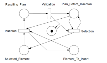 Figure 9: Validation approach
The initial marking of places “Plan_Before_Insertion” and “Element_To_Insert” are respectively {[beg_seq, end_seq]} and {beg_seq, end_seq, cont_act, elem_act, par, pre, iter, cond, bool_exp, loops_num}. Initially, place “Selected_Element” has an empty marking and so is place “Resulting_Plan”.
The transition “Selection” (respectively “Insertion”) models an element selection (respectively insertion) of (respectively in) the plan. As far as transition “Validation” is concerned, it represents the formal syntax analyzer of the language PILOT. The mechanism implemented for the syntax-oriented building of plans is free of errors if the Petri net of Figure 9 does not contain any deadlock.
For the application of this certification method to the syntax-oriented editor of PILOT plans, a syntax-checker has been built in PROLOG based on the approach suggested in [29]. Thereafter, the plan construction has been modeled and the properties hereafter have been checked:
- Are there insertions that lead to plans whose syntax is not correct?
- Are there plans with correct syntax whose construction is not possible with the proposed insertion model?
The first property aims at ensuring that the proposed syntax-oriented building mechanism disallows the construction of plans whose syntax is not correct. Regarding the second property, the goal is to make sure that the mechanism does not disallow the building of correct plans. Indeed, the checking mechanism may be too restrictive and lead to the rejection of plans that are syntactically correct.
Due to the working of PROLOG, it was necessary to limit the size of the set of plans built. If not, the PROLOG tool would have tried to generate all syntactically correct plans and this would have led to memory space problems. PROLOG parser and plan construction models were therefore modified to solely generate plans of size under a threshold. Here, the size is that of the list modeling the plan. Figure 10 shows the translation of the above properties in PROLOG, taking the size constraint into account. In this PROLOG code, convert converts a model representing the graphic plan into a model which the syntax analyzer can process. convert_set works similarly, but applies to set of models.
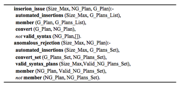 Figure 10: Syntax analyzer’ properties validity translation in Prolog
SWI-Prolog tool of University of Amsterdam were used for the programming. The tests performed for plans of size under 15 showed no insertion problem and no anomalous rejection. Consequently, for plans whose size is under 15, the proposed syntax-oriented building mechanism enables constructing only but all plans whose syntax is valid. For greater sizes, an exception related to lack of memory space is raised. The lack of space is caused by the exponential increase of the set of plans.
The next section presents the modeling of PILOT plans’ properties as well as the modeling of plans’ building operations, for their verification using Prototype Verification System. As indicated in the third section, Prototype Verification System offers a theorem proving system which enables to avoid the aforementioned memory space problem.
6. Plans and operations modeling for properties verification using Prototype Verification System
6.1. Prolog approach model analysis
In the approach used for PILOT’s syntax-oriented editor properties’ proof using SWI-Prolog, plan’s model is a numbered elements list, so as to be able to locate components of the plan as in its graphical version. Indeed, for operations such as insertion, it is necessary identifying where insertion is wished. In PILOT’s Graphical User Interface (Figure 11), in order to insert an element in a plan, the user selects the element among the operators list on the left, then he clicks on the location of the plan before which he wants to insert the element.
 Figure 11: Graphical User Interface of PILOT
The use of numbers to locate the components of the plan is suitable to produce all the plans buildable by insertion of a unique primitive of the language within a plan. Nonetheless, it becomes an obstacle to the generalization needed for theorem proving with the help of Prototype Verification System, the reasoning being done independently of the size of the plan. One of the main difficulties was therefore to find a model of representation of the plan, not based on the numbering of its elements, and making it possible to uniquely locate its elements.
Building and syntax-checking operations necessitate identification of each plan element’s container. Indeed, the behavior of operations such as insertion is container-dependent. Mechanisms such as that provided by SWI-Prolog through the notation “par: number: List” make it easy to isolate blocks and locate the containers. PVS offers no similar mechanism. Therefore, the design of a solution for containers’ identification is needed for PVS.
6.2. Models proposal for the proof of properties with PVS
Proving PILOT editor’s properties with PVS, necessitates defining various models notably for PILOT plan, selection’s container and operation “selection” that specifies where to perform the insertion in the plan. The models proposed for these different entities are presented hereafter.
a) Plan model
The plan is represented as a list of elements belonging to the set {bs, es, e, c, exp, par, pre, condi, iter} (see example on Figure 12). These elements refer to PILOT’ syntax terminals. bs denotes sequence beginning, es sequence end, e (respectively c) elementary (respectively continuous) action, exp expression of conditional. pre, par, condi and iter respectively denote preemption, parallelism, conditional and iteration primitives.
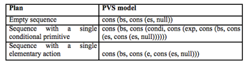 Figure 12: Examples of plans modeled in PVS
b) Modeling properties of syntactically correct plans
In the proposed approach, each rule of the grammar of the language is represented using a two parameters function whose first parameter is the part of the plan submitted for parsing and the second is the remainder expected after retrieving the pattern matching the rule. The output of the function is true when the real and expected remainders are identical. Otherwise, it is false. In Prolog’s case, this approach enables to automatically generate the program that recognizes the language, as shown in Table 1.
Using the same approach under PVS, the program recognizing the language PILOT has the shape shown in Figure 13.
It turns out that this solution cannot be used as such under PVS. Indeed, in PVS’s description language, a function call can only be done after the definition of the function. So, in figure 13, the call to seq_base in the definition of validplan isn’t concretely allowed. An approach to solve this problem could be just to specify (declare) the function before the call without defining it completely, but it is disallowed in Prototype Verification System.
A first method adopted to overpower these drawbacks has been to elaborate PILOT syntax rules’ dependencies graph, then using it to define the functions in the order of dependency, beginning by the functions not involving cross recursive calls, and then using the passing of functions as parameters to define functions involved in calls with cross recursion. The principle is shown hereafter through a definition of even and odd parities:
Table 1: Description of PILOT’s syntax with Prolog
| PILOT Syntax rules | Description in Prolog | ||
| S | : SEQ_BASE | validplan (A,B) | :- seq_base (A,B). |
| SEQ_BASE | : bs L_PRIMI_BASE es | seq_base ([bs|A],B) | :- l_primi_base (A, [es,B]). |
| L_PRIMI_BASE | : e | | l_primi_base (A,A). | |
| PRIMI_BASE L_PRIMI_BASE | l_primi_base (A,B) | :- primi_base (A,C), l_primi_base (C,B). | |
| PRIMI_BASE | : PRIMI_PARALLEL | | primi_base (A,B) | :- primi_parallel (A,B). |
| PRIMI_PREEMPTION | | primi_base (A,B) | :- primi_preemption (A,B). | |
| PRIMI_CONDITIONAL | | primi_base (A,B) | :- primi_conditional (A,B). | |
| PRIMI_ITERATION | | primi_base (A,B) | :- primi_iteration (A,B). | |
| PRIMI_ACT_ELEM | primi_base (A,B) | :- primi_act_elem (A,B). | |
| PRIMI_PARALLEL | : par ‘(‘ LIST_SEQ ‘)’ | primi_parallel ([par,‘(‘|A],B) | :- list_seq (A, [‘)’| B]). |
| LIST_SEQ | : LIST_SEQ_A SEQ_BASE LIST_SEQ_A | list_seq (A,B) | :- list_seq_a (A,C), seq_base(C,D), list_seq_a (D, B). |
| LIST_SEQ_A | : e |
SEQ LIST_SEQ_A |
list_seq_a (A,A). | |
| list_seq_a (A,B) | :- seq (A, C), list_seq_a (C,B). | ||
| SEQ | : SEQ_BASE |
SEQ_SPECIFIC |
seq (A,B) | :- seq_base (A,B). |
| seq (A,B) | :- seq_specific (A,B). | ||
| SEQ_SPECIFIC | : bs PRIMI_ACT_CONT es | seq_specific ([bs|A],B) | :- primi_act_cont (A,[es|B]). |
| PRIMI_ACT_CONT | : c | primi_act_cont ([c|A],A). | |
| PRIMI_PREEMPTION | : pre ‘(‘ LIST_SEQ ‘)’ | primi_preemption ([pre,‘(‘|A],B) | :- list_seq (A, [‘)’| B]). |
| PRIMI_CONDITIONAL | : condi ‘(‘ LIST_CONDITIONAL ‘)’ | primi_conditional ([cond,‘(‘|A],B) | :- list_conditional (A,[‘)’,B]). |
| LIST_CONDITIONAL | : CONDITIONAL LIST_CONDITIONAL |
CONDITIONAL |
list_conditional (A,B) | :- conditional (A,C), list_conditional (C,B). |
| list_conditional (A,B) | :- conditional (A,B). | ||
| CONDITIONAL | : exp SEQ_BASE | conditional ([exp|A],B) | :- seq_base (A,B). |
| PRIMI_ITERATION | : iter ‘(‘ SPEC_ITER ‘)’ | primi_iteration ([iter,‘(‘|A],B) | :- spec_iter (A, [‘)’|B]). |
| SPEC_ITER | : CONDITIONAL |
nb SEQ_BASE |
spec_iter (A,B) | :- conditional (A,B). |
| spec_iter ([nb|A],B) | :- seq_base (A, B). | ||
| PRIMI_ACT_ELEM | : e | primi_act_elem ([e|A],A). | |
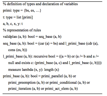 Figure 13: Specification of PILOT syntax in PVS with same method as Prolog
Even (n: N): Boolean = n=0 or (n ¹0 and odd (n-1))
Odd (n: N): Boolean = n=1 or (n ¹1 and even (n-1))
This definition of even and odd functions can be transformed in PVS as shown in figure 14.
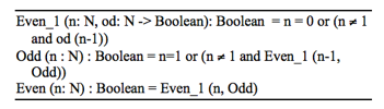 Figure 14: Representation of even and odd functions for PVS with resolution of recursive crossed calls
Nevertheless, the syntax of PILOT contains several complex crossed calls involving more than 2 crossed calls. For example, “seq_base” refers to “l_primi_base” that refers to “primi_base” which refers in turn to “primi_parallel” that also refers to “seq_base”.
Under PVS, defining a function that is recursive also necessitates adding a function called measure which decreases in the course of recursive calls and having a down side limit, so as to ensure recursive calls ending.
Figure 15 illustrates the representation proposed in order to solve the problem related to recursive cross calls for the example mentioned above.
A representation of PILOT’s syntax under PVS has been generated with the help of this approach. For its validation, the obligations of proofs produced by Prototype Verification System were proven and a few plans’ definition theorems, among which those in Figure 16, have been defined and proved with the help of PVS.
a) Modeling of plan element selection
The intention is to design a model representing the point of insertion in the PILOT plan. The following two components can be used for characterizing the point of insertion: the clicked element and its container. The proposed model of representation of the selected element is the couple (Lbe, Laf) where Lbe corresponds to the head of the plan list ending just before the selected element, and Laf is the remaining of the plan starting from the selected element. This solution makes it possible to take advantage of the properties of concatenation of lists in the design of the models of operations that apply to the selected element. It also provides a good consistency with the syntactic rules modeling where two parts of the list representing the plan have to be distinguished, namely the part recognized by the rule and the remainder.
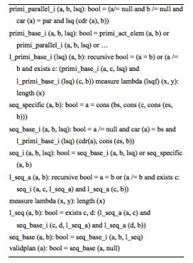 Figure 15: Excerpt of PILOT’s syntax description in PVS with cross recursive calls solving
In the proposed modeling, the selected element’s container is frequently split in two parts, one belonging to Lbe and the other to Laf. Plan element selection model is shown in Figure 17. In this model, Lcon is the tail of the plan that starts from the selected element’s container.
An extract of the PVS model of the selection operation is given in Figure 18. It shows the specification of the selection of an outermost plan’s element (i.e. an element of the main sequence of the plan), as well as the case of a selection within a parallel box. In the first case, there is no container, whereas in the second case, the parallel box is the container.
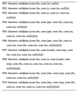 Figure 16: Samples of PVS demonstrated theorems
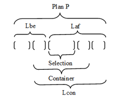 Figure 17: Selection model of a plan element
In this selection operation, “fusion” is an operation that performs the fusion of two lists and “seq” is such that its first parameter is a list L starting by a sequence S followed by a list LS2 of primitives.
7. Conclusion
As shown in the state of the art part of this paper, it is necessary to develop the use of theorem provers for robotic systems, given their complexity that makes their verification with model checkers prone to the state-space explosion problem. This work is a step forward in this direction, through a case study showing the limits of model-checking for the proof of properties of a robotic system, namely the syntax-oriented editor of a robotic missions programming language (PILOT), and investigating the use of the PVS theorem proving system to overcome the problem encountered with the model-checking approach.
Another goal of the work was to check out the appropriateness of Prototype Verification System for accomplishing complicated demonstrations that involve the design of models for different kinds of entities frequently encountered in robotics and more generally in control-command systems (language syntax, operations …).
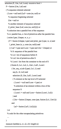 Figure 18: Extract of selection operation’s PVS model
In order to reach these goals, PVS functions have been used to represent PILOT’s syntax. The proposed model has been validated notably by verifying the obligations of proofs produced by Prototype Verification System and proving some theorems defined on PILOT plans. The modeling of recursive cross-calls has been the major issue faced during PILOT’s syntax specification in PVS. As matter of fact, contrary to Prolog, the language of specification provided by PVS disallows to use a function before its full definition. Consequently, a PVS model without cross recursivity was proposed. The specification in PVS of the selection operation of the syntax-oriented editor of PILOT has also been presented in this paper.
The results obtained at this step of the work (the representation model of the syntax rules of the language PILOT under PVS and its validation, the modeling of operations of the syntax-oriented editor of PILOT), enables to conclude in a good capacity of PVS for the modeling of aforementioned entities of control-command systems and for the achievement of further formal proofs.
Conflict of Interest
The authors declare no conflict of interest.
Acknowledgment
This work was supported by Lab-STICC (UMR CNRS 6285) and University of Brest.
- L. Nana, F. Monin, S. Gire, “Proof of properties of a syntax analyzer of robotic mission plans” in Proceedings of 4th International Conference and Workshops on Recent Advances and Innovations in Engineering –ICRAIE 2019, IEEE, Kedah, Malaysia, 2019.
- M. Barbier, J. F. Gabard, D. Vizcaino, O Bonnet-Torrès, “ProCoSA: a software package for autonomous systems supervision” in Proceedings of 1st National Workshop on Control Architectures of Robots: software approaches and issues, Montpellier, France, 2006.
- C. Barrouil, J. Lemaire, “Advanced Real-Time Mission Management for an AUV” in Proceedings of SCI NATO RESTRICTED Symposium on Advanced Mission Management and System Integration Technologies for improved Tactical Operations, Florence, Italy, 1999.
- L. Laouamer, A. Benhocine, L. Nana, A Pascu, “Motion JPEG Video Authentication based on Quantization Matrix Watermarking: Application in Robotics” Int. J. Comput. Appl., 47(24), 1-5, 2012.
- L. Nana, “Investigating safety mechanisms for robotics applications” IPSI BGD Trans. Internet Res., 3(1), 45-50, 2006.
- L. Nana, L. Marcé, J. Opderbecke, M. Perrier, V. Rigaud, “Investigation of safety mechanisms for oceanographic AUV missions programming” in Proceedings of the IEEE OCEANS’05 Europe Conference, Brest, France, 2005.
- L. Nana, F. Singhoff, J. Legrand, J. Vareille, P. Le Parc, F. Monin, D. Massé, L. Marcé, J. Opderbecke, M. Perrier, V. Rigaud, “Embedded intelligent supervision and piloting for oceanic AUV” in Proceedings of the IEEE OCEANS’05 Europe Conference, Brest, France, 2005.
- L. Nana, J. Legrand, F. Singhoff, L. Marcé, “Modelling and Testing of PILOT Plans Interpretation Algorithms” in Proceedings of Multi-conference on Computational Engineering in Systems Applications, CESA’03, IEEE, Lille, France, 2003.
- L. Nana Tchamnda, V-A. Nicolas, L. Marcé, “Towards a formal approach for the regeneration of PILOT control system” in Proceedings of 6th World Multiconference on Systemics, Cybernetics and Informatics, SCI’2002, IEEE Venezuela, Orlando, Florida, USA, 2002.
- F. Py, F. Ingrand, “Dependable Execution Control for Autonomous Robot” in Proceedings of IROS 2004 (IEEE/RSJ International Conference on Intelligent Robots and Systems), Sendai, Japan, 2004.
- E. Rutten, “A framework for using discrete control synthesis in safe robotic programming”, Research report, INRIA, 2000.
- N. Turro N, “MaestRo: Une approche formelle pour la programmation d’applications robotiques”, PhD Thesis, Université de Nice, Sophia Antipolis, 1999.
- J. F. Groote, F. Monin, J. C. Van de Pol, “Checking verifications of protocols and distributed systems by computer” in Proceedings of Concur’98, Sophia Antipolis, France, 1998.
- J.F. Groote, F. Monin, J. Springintveld, “A computer checked algebraic verification of a distributed summation algorithm”. Form. Asp. Comput. 17(1), 2005, 19–37. DOI:https://doi.org/10.1007/s00165-004-0052-7.
- D. Bresolin, L. Di Guglielmo, L. Geretti, R. Muradore, P. Fiorini, T. Villa, “Open problems in verification and refinement of autonomous robotic systems” in Proceedings of the 15th Euromicro Conference on Digital System Design, pp. 469-476, Cesme, Izmir, Turkey, 2012.
- E. Zereik, M. Bibuli, N. Miskovic, P. Ridao, A. Pascoal, “Challenges and future trends in marine robotics” Annu. Rev. Control, 46, 2018, 350-368, ISSN 1367-5788. https://doi.org/10.1016/j.arcontrol.2018.10.002.
- M. Ludvigsen, A. J. Sørensen, “Towards integrated autonomous underwater operations for ocean mapping and monitoring”. Annu. Rev. Control, 42, 145-157, 2016.
- A. J. Barry, A. Majumdar, R. Tedrake, “Safety verification of reactive controllers for UAV flight in cluttered environments using barrier certificates” in Proceedings of 2012 IEEE International Conference on Robotics and Automation, Saint Paul, MN, USA, pp. 484-490, 2012. doi: 10.1109/ICRA.2012.6225351
- C. Armbrust, L. Kiekbusch, T. Ropertz, K. Berns, “Tool-assisted verification of behavior networks” In proceedings of 2013 IEEE International Conference on Robotics and Automation, Karlsruhe, Germany, pp. 1813-1820, 2013. doi: 10.1109/ICRA.2013.6630816
- M. Luckcuck, M. Farrell, L. A. Dennis, C. Dixon, M. Fisher, “Formal Specification and Verification of Autonomous Robotic Systems: A Survey” ACM Comput. Surv. 52(5), 2019, Article 100, 41 pages. DOI: https://doi.org/10.1145/3342355
- S. Dehnavi, A. Sedaghatbaf, B. Salmani, M. Sirjani, M. Kargahi, E. Khamespanah. “Towards an Actor-based Approach to Design Verified ROS-based Robotic Programs using Rebeca” Procedia Comput. Sci., 155, 59-68, 2019, ISSN 1877-0509, https://doi.org/10.1016/j.procs.2019.08.012.
- A. Rashid, O. Hasan, I. T. Bhatti, Formal Verification of Robotic Cell Injection Systems, Editor(s): Ahmad Taher Azar, Control Systems Design of Bio-Robotics and Bio-mechatronics with advanced applications, Academic Press, 2020.
- S. Owre N. Shankar, J. M. Rushby, D. W. J. Stringer-Calvert, “PVS System Guide”, Technical Report, SRI International, Menlo Park, CA, 1999.
- S. Owre N. Shankar, J. M. Rushby, D. W. J. Stringer-Calvert, “PVS Language Reference”, Technical Report, SRI International, Menlo Park, CA, 2001.
- N. Shankar S. Owre, J. M. Rushby, and D. W. J. Stringer-Calvert, “PVS Prover Guide”, Technical Report, SRI International, Menlo Park, CA, 1999.
- J.-L. Fleureau, “Vers une méthodologie de programmation d’un système de télérobotique : comparaison des approches PILOT et Grafcet”, PhD Thesis, Université de Rennes 1, 1998.
- E. Le Rest, “PILOT : un langage pour la télérobotique”, PhD Thesis, Université de Rennes 1, 1996.
- K. Jensen, Coloured Petri Nets – Basic Concepts, Analysis Methods and Practical Use, Springer-Verlag Berlin Heidelberg, 1997
- F. Giannesini, H. Kanoui, R. Pasero, M. Van Caneghem, Prolog, InterEditions, 1985.