Current Control of Battery-Supercapacitors System for Electric Vehicles based on Rule-Base Linear Quadratic Regulator
Volume 6, Issue 1, Page No 57-65, 2021
Author’s Name: Taha Sadeqa), Chew Kuew Wai, Ezra Morris
View Affiliations
Lee Kong Chian Faculty of Engineering and Science, Universiti Tunku Abdul Rahman, Sungai Long Campus, Selangor 43000, Malaysia
a)Author to whom correspondence should be addressed. E-mail: eng.tahasadeq@1utar.my
Adv. Sci. Technol. Eng. Syst. J. 6(1), 57-65 (2021); ![]() DOI: 10.25046/aj060107
DOI: 10.25046/aj060107
Keywords: Batteries, Current Control, Electric Vehicle, Supercapacitors, Linear Quadratic Regulator

Export Citations
This research aims to investigate the energy and power management of a battery-supercapacitors Hybrid Energy Storage System (HESS) for Electric vehicles (EVs). A bidirectional DC-DC converter, a battery and a set of supercapacitors were employed to construct the parallel semi-active architecture of HESS. Two strategies of Rule-Base Linear Quadratic Regulators (R-B LQRs) were proposed to manage the power flow in HESS to reduce the overall battery stress during high demand events. The supercapacitors supply the high load demand, while the battery supplies the low load demand. The HESS, EV and the proposed controllers were simulated in a MATLAB/Simulink environment. Three standard drive cycles, namely, Urban Dynamometer Driving Schedule UDDS, New York City Cycle NYCC and Japan1015 drive cycle, were implemented to validate the controller’s responses. The results of the R-B LQR controllers were compared in terms number of possible drive cycles. According to the results achieved, the proposed hybridization achieves stable response of the HESS current over the drive cycles, effectively reducing the battery’s size and extends its life-time.
Received: 17 September 2020, Accepted: 23 December 2020, Published Online: 10 January 2021
- V. Paladini, T. Donateo, A. de Risi, D. Laforgia, “Super-capacitors fuel-cell hybrid electric vehicle optimization and control strategy development,” Energy Conversion and Management, 48(11), 3001–3008, 2007, doi:10.1016/j.enconman.2007.07.014.
- S.F. Tie, C.W. Tan, A review of energy sources and energy management system in electric vehicles, Renewable and Sustainable Energy Reviews, 20, 82–102, 2013, doi:10.1016/j.rser.2012.11.077.
- P. Sharma, T.S. Bhatti, “A review on electrochemical double-layer capacitors,” Energy Conversion and Management, 51(12), 2901–2912, 2010, doi:10.1016/j.enconman.2010.06.031.
- K.E. Mehrdad Ehsani, Yimin Gao, Stefano Longo, Modern Electric, Hybrid Electric, and Fuel Cell Vehicles, Boca Raton: CRC press, 2010.
- B. Hredzak, V.G. Agelidis, G.D. Demetriades, “A low complexity control system for a hybrid DC power source based on ultracapacitor-lead-acid battery configuration,” IEEE Transactions on Power Electronics, 29(6), 2882–2891, 2014, doi:10.1109/TPEL.2013.2277518.
- J. Cao, A. Emadi, “A new battery/ultracapacitor hybrid energy storage system for electric, hybrid, and plug-in hybrid electric vehicles,” IEEE Transactions on Power Electronics, 27(1), 122–132, 2012, doi:10.1109/TPEL.2011.2151206.
- G. Udhaya Sankar, C. Ganesa Moorthy, G. RajKumar, Smart Storage Systems for Electric Vehicles–A Review, Smart Science, 7(1), 1–15, 2019, doi:10.1080/23080477.2018.1531612.
- L. Kouchachvili, W. Yaïci, E. Entchev, Hybrid battery/supercapacitor energy storage system for the electric vehicles, Journal of Power Sources, 374, 237–248, 2018, doi:10.1016/j.jpowsour.2017.11.040.
- T. Sadeq, C.K. Wai, E. Morris, Q.. Tarbosh, O. Aydogdu, “Optimal Control Strategy to Maximize the Performance of Hybrid Energy Storage System for Electric Vehicle Considering Topography Information,” IEEE Access, 1–1, 2020, doi:10.1109/access.2020.3040869.
- I. Aharon, A. Kuperman, Topological overview of powertrains for battery-powered vehicles with range extenders, IEEE Transactions on Power Electronics, 26(3), 868–876, 2011, doi:10.1109/TPEL.2011.2107037.
- D. Iannuzzi, P. Tricoli, “Speed-based state-of-charge tracking control for metro trains with onboard supercapacitors,” IEEE Transactions on Power Electronics, 27(4), 2129–2140, 2012, doi:10.1109/TPEL.2011.2167633.
- J. Armenta, C. Núñez, N. Visairo, I. Lázaro, “An advanced energy management system for controlling the ultracapacitor discharge and improving the electric vehicle range,” Journal of Power Sources, 284, 452–458, 2015, doi:10.1016/j.jpowsour.2015.03.056.
- F. Ju, Q. Zhang, W. Deng, J. Li, “Review of structures and control of battery-supercapacitor hybrid energy storage system for electric vehicles,” in IEEE International Conference on Automation Science and Engineering, IEEE Computer Society: 143–148, 2014, doi:10.1109/CoASE.2014.6899318.
- A. Kuperman, I. Aharon, Battery-ultracapacitor hybrids for pulsed current loads: A review, Renewable and Sustainable Energy Reviews, 15(2), 981–992, 2011, doi:10.1016/j.rser.2010.11.010.
- O. Laldin, M. Moshirvaziri, O. Trescases, “Predictive algorithm for optimizing power flow in hybrid ultracapacitor/battery storage systems for light electric vehicles,” IEEE Transactions on Power Electronics, 28(8), 3882–3895, 2013, doi:10.1109/TPEL.2012.2226474.
- P. Pany, R. Singh, R. Tripathi, “Bidirectional DC-DC converter fed drive for electric vehicle system,” International Journal of Engineering, Science and Technology, 3(3), 101–110, 2011, doi:10.4314/ijest.v3i3.68426.
- M.B. Camara, H. Gualous, F. Gustin, A. Berthon, B. Dakyo, “DC/DC converter design for supercapacitor and battery power management in hybrid vehicle applicationspolynomial control strategy,” in IEEE Transactions on Industrial Electronics, 587–597, 2010, doi:10.1109/TIE.2009.2025283.
- X. Wang, J. Tao, R. Zhang, “Fuzzy energy management control for battery/ultra-capacitor hybrid electric vehicles,” in Proceedings of the 28th Chinese Control and Decision Conference, CCDC 2016, Institute of Electrical and Electronics Engineers Inc.: 6207–6211, 2016, doi:10.1109/CCDC.2016.7532114.
- P. Golchoubian, N.L. Azad, “Real-Time Nonlinear Model Predictive Control of a Battery-Supercapacitor Hybrid Energy Storage System in Electric Vehicles,” IEEE Transactions on Vehicular Technology, 66(11), 9678–9688, 2017, doi:10.1109/TVT.2017.2725307.
- M. Sellali, S. Abdeddaim, A. Betka, A. Djerdir, S. Drid, M. Tiar, “Fuzzy-Super twisting control implementation of battery/super capacitor for electric vehicles,” ISA Transactions, 95, 243–253, 2019, doi:10.1016/j.isatra.2019.04.029.
- X. Hu, Y. Li, C. Lv, Y. Liu, “Optimal Energy Management and Sizing of a Dual Motor-Driven Electric Powertrain,” IEEE Transactions on Power Electronics, 34(8), 7489–7501, 2019, doi:10.1109/TPEL.2018.2879225.
- T. Sadeq, C.K. Wai, “Linear Quadratic Regulator Control Scheme on Hybrid Energy Storage System,” in 2020 IEEE International Conference on Automatic Control and Intelligent Systems, I2CACIS 2020 – Proceedings, Institute of Electrical and Electronics Engineers Inc.: 219–223, 2020, doi:10.1109/I2CACIS49202.2020.9140093.
- M.R.D. Al-Mothafar, S.M. Radaideh, M.A. Abdullah, “LQR-based control of parallel-connected boost dc-dc converters: A comparison with classical current-mode control,” International Journal of Computer Applications in Technology, 45(1), 15–27, 2012, doi:10.1504/IJCAT.2012.050129.
- D.M. Robert W. Erickson, Fundamentals of Power Electronics, 2nd ed., Springer Science & Business Media, 2007.
- M. Chen, G.A. Rincón-Mora, “Accurate electrical battery model capable of predicting runtime and I-V performance,” IEEE Transactions on Energy Conversion, 21(2), 504–511, 2006, doi:10.1109/TEC.2006.874229.
- A. Shafiei, A. Momeni, S.S. Williamson, “Battery modeling approaches and management techniques for plug-in hybrid electric vehicles,” in 2011 IEEE Vehicle Power and Propulsion Conference, VPPC 2011, 2011, doi:10.1109/VPPC.2011.6043191.
- A. Fotouhi, D.J. Auger, K. Propp, S. Longo, M. Wild, A review on electric vehicle battery modelling: From Lithium-ion toward Lithium-Sulphur, Renewable and Sustainable Energy Reviews, 56, 1008–1021, 2016, doi:10.1016/j.rser.2015.12.009.
- S. Barsali, M. Ceraolo, “Dynamical models of lead-acid batteries: Implementation issues,” IEEE Transactions on Energy Conversion, 17(1), 16–23, 2002, doi:10.1109/60.986432.
- A. Fotouhi, K. Propp, D.J. Auger, “Electric vehicle battery model identification and state of charge estimation in real world driving cycles,” in 2015 7th Computer Science and Electronic Engineering Conference, CEEC 2015 – Conference Proceedings, Institute of Electrical and Electronics Engineers Inc.: 243–248, 2015, doi:10.1109/CEEC.2015.7332732.
- T. Huria, M. Ceraolo, J. Gazzarri, R. Jackey, “High fidelity electrical model with thermal dependence for characterization and simulation of high power lithium battery cells,” in 2012 IEEE International Electric Vehicle Conference, IEVC 2012, 2012, doi:10.1109/IEVC.2012.6183271.
- S. Hussain, M.U. Ali, G.-S. Park, S.H. Nengroo, M.A. Khan, H.-J. Kim, “A Real-Time Bi-Adaptive Controller-Based Energy Management System for Battery–Supercapacitor Hybrid Electric Vehicles,” Energies, 12(24), 4662, 2019, doi:10.3390/en12244662.
- L. Zubieta, R. Bonert, “Characterization of double-layer capacitors for power electronics applications,” IEEE Transactions on Industry Applications, 36(1), 199–205, 2000, doi:10.1109/28.821816.
- N. Devillers, S. Jemei, M.C. Péra, D. Bienaimé, F. Gustin, “Review of characterization methods for supercapacitor modelling,” Journal of Power Sources, 246, 596–608, 2014, doi:10.1016/j.jpowsour.2013.07.116.
- F. Machado, J.P.F. Trovão, C.H. Antunes, “Effectiveness of supercapacitors in pure electric vehicles using a hybrid metaheuristic approach,” IEEE Transactions on Vehicular Technology, 65(1), 29–36, 2016, doi:10.1109/TVT.2015.2390919.
- N.; R.W.P.; U.T. Mohan, Power electronics: converters, applications and design, USA: John Wiley & Sons, 2007.
- M.A. Abdullah, C.W. Tan, A.H.M. Yatim, “A simulation study of hybrid wind-ultracapacitor energy conversion system,” in 2014 IEEE Conference on Energy Conversion, CENCON 2014, Institute of Electrical and Electronics Engineers Inc.: 265–270, 2014, doi:10.1109/CENCON.2014.6967513.
- T. Sadeq, C.K. Wai, “Model the DC-DC Converter with Supercapacitor Module based on System Identification,” in 2019 IEEE International Conference on Automatic Control and Intelligent Systems, I2CACIS 2019 – Proceedings, Institute of Electrical and Electronics Engineers Inc.: 185–188, 2019, doi:10.1109/I2CACIS.2019.8825095.
- S. Gonsrang, R. Kasper, “Optimisation-based power management system for an electric vehicle with a hybrid energy storage system,” International Journal of Automotive and Mechanical Engineering, 15(4), 5729–5747, 2018, doi:10.15282/ijame.15.4.2018.2.0439.
- K. Mahmud, G.E. Town, A review of computer tools for modeling electric vehicle energy requirements and their impact on power distribution networks, Applied Energy, 172, 337–359, 2016, doi:10.1016/j.apenergy.2016.03.100.
- A. Bampoulas, A. Giannakis, S. Tsaklidou, A. Karlis, “Modeling, simulation and performance evaluation of a low-speed battery electric vehicle,” in 2016 11th International Conference on Ecological Vehicles and Renewable Energies, EVER 2016, Institute of Electrical and Electronics Engineers Inc., 2016, doi:10.1109/EVER.2016.7476342.
- C.K. Wai, Y.Y. Rong, S. Morris, “Simulation of a distance estimator for battery electric vehicle,” Alexandria Engineering Journal, 54(3), 359–371, 2015, doi:10.1016/j.aej.2015.04.008.
- E. Schaltz, Electrical vehicle design and modeling, INTECH Open Access Publisher, 2011.
- Q.A. Tarbosh, O. Aydogdu, N. Farah, M.H.N. Talib, A. Salh, N. Cankaya, F.A. Omar, A. Durdu, “Review and Investigation of Simplified Rules Fuzzy Logic Speed Controller of High Performance Induction Motor Drives,” IEEE Access, 8, 49377–49394, 2020, doi:10.1109/ACCESS.2020.2977115.
- N. Farah, M.H.N. Talib, N.S. Mohd Shah, Q. Abdullah, Z. Ibrahim, J.B.M. Lazi, A. Jidin, “A Novel Self-Tuning Fuzzy Logic Controller Based Induction Motor Drive System: An Experimental Approach,” IEEE Access, 7, 68172–68184, 2019, doi:10.1109/ACCESS.2019.2916087.
- B. Kedjar, K. Al-Haddad, “DSP-based implementation of an LQR with integral action for a three-phase three-wire shunt active power filter,” IEEE Transactions on Industrial Electronics, 56(8), 2821–2828, 2009, doi:10.1109/TIE.2008.2006027.
1.Introduction
Nowadays, landed vehicles can be categorized in to three main types, namely, conventional vehicles, Electric Vehicles (EVs) and Hybrid Electric Vehicles (HEVs). Conventional vehicles with an internal combustion engine (ICE) are the most common type in today’s market. In ICEs, chemical energy (e.g. ethanol, gasoline, diesel etc.) is converted into kinetic energy in a process has significant power losses. On the other hand, the EV is an alternative-design automobile that relies on battery power to provide the electricity to actuate the vehicle by an electrical motor. Furthermore, The HEV is powered by two types of energy sources, namely, ICE and electrical motor with ESS; it combine the benefits of high fuel economy and low harmful emissions. Due to the necessity to reduce air pollution and harmful vehicle emissions, significant research has been focused on developing HEVs and EVs. Energy storage systems pose a significant issue in stand-alone applications. Batteries offer a wide range of the clean energy. Furthermore, they have high energy density and low power density due to chemical processes to deliver and store energy [1]. However, the main drawbacks are low cycle-life, and long recharging times. In addition, the immediate response to sudden load changes in charging and discharging could potentially reduce the battery’s lifetime. There are several kinds of chemical batteries that are currently available in the market such as lead-acid, lithium-ion, nickel metal hydride (NiMH) and nickel cadmium (NiCad) [2]. The supercapacitor is another energy storage technology, and is either an electric double layer capacitor (EDLC) or a pseudo-capacitor. These differ in the ways they store energy and charge [3]. Compared to batteries, supercapacitors have relatively low specific energy density and high specific power density. The supercapacitors are used as auxiliary an energy storage device due to the dependence of terminal voltage on the state of charge. Nevertheless, various benefits can achieved when using the supercapacitors as an auxiliary power source [4]. The low value of the terminal voltage is a core limit of supercapacitors; 2.5 volts is the maximum terminal voltage that can be provided by a single supercapacitor unit. However, several supercapacitors are connected in series and in parallel to achieve the required operation voltage and energy capacity by powerful applications. Consequently, many researchers have attempted to improve the performance of the ESS by combining high power devices like supercapacitors or flywheels in parallel with batteries. The main purpose of the Hybrid Energy Storage System (HESS) is to extend the efficacy of each power source [5]. This work designs a semi-active HESS by engaging a battery in parallel form with supercapacitors through a DC-DC converter, with the aim of increasing the merits of the two devices, and decrease their limitations [6].
The essential challenge in the design of a HESS for EV is to manage the current flow between the supercapacitors and the battery. The advantages and disadvantages of many topologies of HESS have been reviewed extensively in the existing literature [7–9]. Furthermore, in the literature, the HESS used several types of bidirectional DC-DC converters. Figure 1 illustrates six different topologies of HESS. Figure 1(a) presents the simplest topology of a battery-supercapacitor system. Due to the direct connection, the battery and the supercapacitors voltage terminal remains the same, and the DC-DC converter is used to maintain the power flow. In this topology, the supercapacitor characteristics are limited. Furthermore, a full-sized DC-DC converter is needed to manage the delivered energy [10]. The configuration in Figure 1(b) is widely used in the literature [11, 12]. The bidirectional DC-DC converter was placed between the DC-Bus and the supercapacitors as an interface to manage the current flow in HESS. Reliability is the main feature of this topology, where the load current is not affected by the failure of the DC-DC converter. Figure 1(c) shows another configuration of a HESS. In this topology, the power flow of the battery was maintained within a safe range via the DC-DC converter. The supercapacitor operational range was limited, and it responded as an energy buffer [13]. The topologies represented in Figure 1(d, f) used two DC-DC converters to manage the power flow from the battery and supercapacitors, individually. These topologies require a full and medium sized DC-DC converter for every source. In addition, the loss, cost and weight are increased in this topology compared to the other topologies, in terms of the need for full-sized DC-DC converters [14, 15]. The scheme in Figure 1(e) uses a parallel connection of batteries and supercapacitors via two DC-DC converters separately, and suffers from the same constrains in Figure 1(d, f).
 Figure 1: Most common HESS architectures [2].
On the other hand, many researches presented various models of bidirectional DC-DC converter designs for HESS [16,17]. The DC-DC converter was used to manage the current flow of HESS under transient and steady-state conditions. Many researches in the literature used different control algorithms to control the power flow of the HESS. In [17], the polynomial control strategy was used to manage the energy for two DC-DC converters, and the results are sufficient compared to the classical PI. Furthermore, recent studies focused on rule-based approaches such as fuzzy logic control [18] to manage the power flow in the HESS. The accuracy in measurement noise and adaptation of fuzzy logic was used as an energy management strategy. However, human experience was implemented to design the membership function and fuzzy rule. Therefore, this cannot guarantee suitable control performance in unexpected conditions. In [19], the response of a non-linear model predictive controller was compared to a linear model predictive controller and rule-base control, based on the hybrid battery supercapacitors energy storage system for EV. In other work aiming to extend battery life-cycle, a rule-based controller of HESS was compared to a fuzzy controller, and the results show that in transient the controllers supplied the EV load current from the supercapacitor, while the battery supplied the load during the steady state [20]. In [21], the researchers tried to extend the driving cycle and decrease the size of the HESS by using multi-objective optimization. Three standard drive cycles were used to validate the proposed controller.
This research aims to design a control algorithm for HESS for an EV. Two control strategies of R-B LQR were proposed to be implemented as controllers in EV applications due to their simplicity to implement and short computation time compared with to optimization methods. The limit R-B LQR aims to limit the battery current to Ib_max while the share limit R-B LQR aims to limit the battery current to Ib_max, and share the load current between the battery and supercapacitor. Dual control layers were used in this work. The rule-based approach was used to obtain the desired supercapacitors current during the load demand. The LQR was used to control the DC-DC converter by manipulating the width of the duty cycle of PWM. In addition, the LQR controller can guarantee good close-loop behavior for the DC-DC converter, and it is relatively insensitive to external disturbances, since the controller feedback gain-vector has to be determined optimally [22, 23].
This paper is organized as follows. Section 2 discusses the HESS configuration. Section 3 discusses the modeling of the HESS and EV. Section 4 contains the proposed controller algorithm. The simulation results of the proposed controller are presented in Section 5. Section 6 concludes of this research.
- System Configuration
In EV applications, a practical HESS should be light, highly reliable, and have fast response for load variation. Due to the previous reasons, the semi-active architecture in Figure 1(b) was selected to be implemented in this work. Figure 2 shows the semi-active topology of HESS in Matlab/Simulink. The model of the battery is connected directly to the model of the EV as a premier energy source, and the model of the supercapacitors is connected to the EV model through the bidirectional DC-DC converter model as an auxiliary energy source. Three different standard drive cycles, namely, UDDS, NYCC and Japan1015, were used to validate a performance of the proposed controllers.
The limit R-B LQR controller was designed to manage the current flow of the HESS by limiting the current of the battery to Ib_max. The supercapacitors supplied the peak load demand of the EV. Furthermore, the share limit R-B LQR controller was designed to manage the current flow of the HESS by limiting the current of the battery to Ib_max, and sharing the load current between the battery and the supercapacitors. The bidirectional DC-DC converter has two functions; it works as a boost converter during the acceleration of the vehicle to discharge the supercapacitors energy, and also works as a buck converter during the deceleration to absolve and store the regenerative current. The maximum gain of the terminal voltage for the DC-DC converter was set as less than three, to increase the overall efficiency of the system [24].
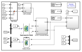 Figure 2: The parallel semi-active architecture of HESS for EV.
- The Modelling of the HESS System
In order to verify the proposed algorithm of the HESS for EV, an accurate model comprising the battery, supercapacitors, DC-DC converter and Electric Vehicle was required. Several different models of HESS components have been presented in the literature.
3.1. Model of the Battery
An equivalent circuit model is a common model that uses electrical components to model the behavior of the battery. There are many approaches to represent the electrical equivalent circuit model for the battery. The majority of these representations fall into three main classifications: Thevenin, impedance and runtime-based models [25–27] . Electrochemical batteries have a complex and nonlinear behavior during charging and discharging, depending on the battery’s state-of-charge (SOC) and electrolyte temperature. For this reason, the researchers in [28] attempted to find a dynamic model that represents this nonlinearity. Furthermore, some researchers used the system identification technique to estimate the parameter values of the battery model [29]. Other researchers used the parameter estimation technique to obtain the parameter values for equivalent model of the battery [30]. Moreover, the thermal effect was considered in the battery models in these works.
The battery model can be found in the MATLAB/Simulink/SimPowerSystems library. This equivalent model contain a control voltage source and an internal resistance, as shown in 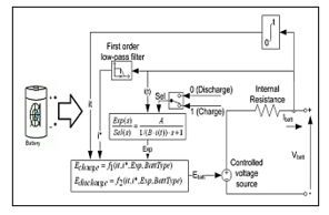 Figure 3. The relationship between the time-varying parameters in the battery model is shown in Equation 1.
![]() The battery current reduction ratio (BCRR) can be calculated by Equation 2 [31].
The battery current reduction ratio (BCRR) can be calculated by Equation 2 [31].
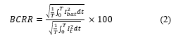 Figure 3: Equivalent model of the battery in SimPowerSystems library
3.2. Model of the Supercapacitors
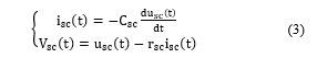
Supercapacitors are commonly used in academia and in the automotive industry due to their high efficiency, low internal resistance, high power density, and long cycle-life. Equation 3 describes the behavior of the supercapacitor, which mathematically depends on the essential laws of a capacitor.
 The design of the energy management system requires a model with good robustness and high precision, representing the dynamics behavior of the supercapacitor . The practical models proposed in [32] consists of three RC branches, and the parameters were determined from the terminal measurements of charging and discharging the supercapacitors. Other models that describe the behavior of supercapacitors are called dynamic models. The transient behavior of the supercapacitors is simulated by these models. The model parameters are identified through experimental tests, such as discharge and charge by the supercapacitor at constant current and electrochemical impedance spectroscopy in environmental constraints [33]. The supercapacitors model in MATLAB/Simulink/SimPowerSystems was used in this research.
3.3. Model of the DC-DC Converter
The model that describes the behavior of the DC-DC converter is important for designing the HESS controller, because the controller aims to control the bidirectional DC-DC converter to supply the required power from the supercapacitors. The terminal output voltage and output current of the bidirectional DC-DC converter were regulated by changing the width of the duty cycle of the PWM, which is applied to the IGBT of the bidirectional DC-DC converter. In this work, a solo layer of the bidirectional DC-DC converter was used to control the current flow of the supercapacitors in both directions. The boost converter was used to discharge, and the buck converter used to charge, the supercapacitors. Figure 4 represents the construction and main elements of the DC-DC converter [34].
The state-space average approach was used to model the bidirectional DC-DC converter. The nonlinear characteristics of the bidirectional DC-DC converter approximates to linear characteristics in the state-space average model. The OFF and ON status of the switching element was involved in the modeling of the DC-DC converter. The time averaging performance of the DC-DC converter is set as:
![]() where:
where:
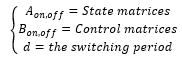
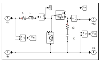 Figure 4: The main components of DC-DC converter
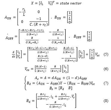
Due to Figure 4, the control and state matrices of the bidirectional DC-DC converter in the OFF and ON conditions are represented as the following matrices:
 The parameters of the DC-DC converter were selected based on the hypotheses in [35]. The model of the DC-DC converter in Figure 4 was approximated by compensating the switching elements with an integration of controlled voltage and current sources, as represented in Figure. 5. This estimated model has good accuracy and reduces the overall simulation time [36]. Other methods were used to estimate the discrete function of the DC-DC converter in [37] by using the system identification technique.
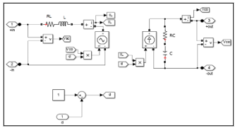 Figure 5: Equivalent model of the bidirectional DC-DC converter
3.4. Electric Vehicle Model
To improve the energy consumption an accurate model representing the EV’s behavior is needed. Many MATLAB/Simulink environment was used to develop few EV models by the researchers, whilst others depends on ADVISOR or equivalent software to analyze and compare the performance of a vast types of vehicles [29, 38–41]. In [4, 42] the dynamic system of the vehicles was defined clearly. The essential dynamics of the vehicles, the forces affecting the vehicles movement are acceleration force (Faccel), grading force (Fgrad), rolling force (Froll) and aerodynamic force (Faero) as shown in Equation 9. The motor drive were controlled the fuzzy logic control as in [43, 44].
![]() where:
where:
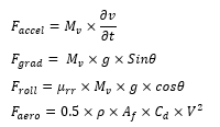 Table 1: The main coefficients of the EV model
| Parameter | Value |
| Mv ≡ Vehicle Mass [kg] | 1325 |
| Af ≡ Frontal area [m2] | 2.57 |
| Cd ≡ Drag coefficient | 0.26 |
| μrr ≡ rolling resistance | 0.0048 |
| Wheel radius [m] | 0.3 |
| ρ ≡ Air density [kgm-3] | 1.29 |
| g ≡ Gravity acceleration [ms-2] | 9.8 |
| V ≡ Vehicle Speed [ Kmh-1] | Variable |
| θ ≡ Road angle [radian] | 0 |
- Rule-Based Linear Quadratic Regulator Control
The linear quadratic regulator (LQR) is a control technique that generates feedback gains. It is used to regulate the output of the system to achieve the optimal performance by controlling one state of the model. The cost function for a continuous-time linear control is defined as:
![]() LQR returns the solution S of the associated Riccati Equation:
LQR returns the solution S of the associated Riccati Equation:
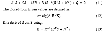
where R is a positive and Q is a symmetric positive definite matrix scalar. Furthermore, The LQR controller used a systematic procedure to calculate the state feedback control gain matrix. R and Q represent the weighted matrices which have a significant effect on the locations of the closed-loop poles [22]. The closed-loop response of the system changes depending on the values of the Q and R matrices. The weighting matrices can be obtained by using optimization methods. Investigating the optimal value of Q and R is beyond the scope of this research. Otherwise, the mathematical model of the DC-DC converter was used to design the controller of the switching elements of the DC-DC converter. The primary task of the rule-based control is to obtain the reference input current of the DC-DC converter, while the aim of the LQR is to obtain a desired duty cycle by the DC-DC converter. The LQR function in MATLAB was used to obtain the desired closed-loop feedback gains, while the steady-state errors were cancelled by adding an integration [45], as shown in Figure 6.
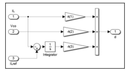 Figure 6: The feedback gains of the LQR controller
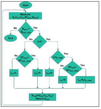 Figure 7: The flowchart of the limit R-B LQR controller
In this research, two strategies for the Rule-base LQR technique were designed to manage the power flow in the HESS. The limit R-B LQR was designed to limit the battery current to Ib_max, and supply the balance load current from the supercapacitors, when the total load current is more than Ib_max , and the state of charge for the supercapacitors more than 30%. On the other hand, the controller leads the supercapacitors to absorb the regenerative energy when the load current is negative and the state of charge of the supercapacitors is less than 95%. Furthermore, if the total load current is less than Ib_max , the controller supplies the total load current from the battery only. The flowchart in Figure 7 illustrates the algorithm of the proposed limit R-B LQR controller.
Moreover, the share limit R-B LQR was designed to limit the battery current to Ib_max, and supply 30% of the load current from the supercapacitors, when the total load current is positive and the state of charge for the supercapacitors is over 30%. The supercapacitors absorb the regenerative energy when the load current is negative and the state of charge of the supercapacitors is less than 95%. The flowchart in Figure 8 illustrates the algorithm of the proposed share limit R-B LQR controller.
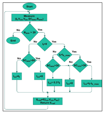 Figure 8: The flowchart of the share limit R-B LQR controller
- Simulation Results and Discussions
This work used MATLAB/Simulink to simulate the semi-active HESS model and the response of the proposed controllers. To validate the proposed limit R-B LQR and share limit R-B LQR for the EV, the dynamic responses of three standard drive cycles (i.e. UDDS, NYCC and Japan1015) were investigated. Figures 9a, 9b, and 9c illustrate the speed profiles for UDDS, NYCC and Japan1015 respectively.
The high peak and fast dynamic discharge and charge load in the EV application reduced the battery life-cycle. The proposed R-B LQR control strategies aim to reduce the battery stress and extend the number of the repeated drive cycles. The battery and supercapacitors sizing optimizations are beyond the scope of this research. Figures 9b, 10b, and 11b demonstrate the total power demand of UDDS, NYCC and Japan1015 for the EV respectively. The battery’s initial state of charge was 0.95, and the initial state of charge of the supercapacitors was 0.55. The definitive state of charge for the supercapacitors and battery of the HESS were taken at the termination of the single drive cycle.
 Figure 9: The acceleration and deceleration Speed profile for: (a) UDDS, (b) NYCC, (c) Japan1015 drive cycle
The results of the proposed HESS were compared to the battery power of the battery alone system, to prove the effectiveness of the R-B LQR controllers for HESS in terms of reducing the battery peak current. The results of a limit R-B LQR and share limit R-B LQR were compared in terms of the number of the possible drive cycles. The proposed controllers was tested in three different drive cycles to validate the algorithm in a wide range of driver behaviors and driving environments. Figure 11 shows the limit R-B LQR response currents of HESS for the UDDS, NYCC and Japan1015 drive cycles. The battery power peak of HESS was limited compared to the battery power of the battery alone system. In the limit R-B LQR algorithm, the battery current supplied the low load current for the EV, and was limited by Ib_max 20A, while the supercapacitors supplied the high load current more than Ib_max 20A, and absorbed all the regenerative current during braking. The limitation of the battery current leads to a reduction in the battery stress of the EV. This algorithm used the stored energy in the supercapacitors during the deceleration to enhance the battery in HESS of the EV.
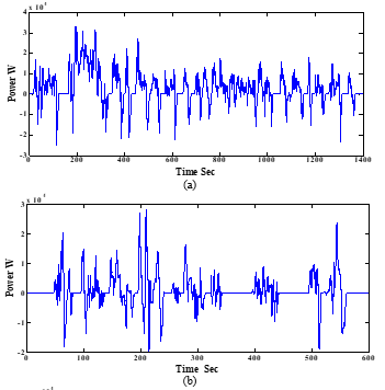
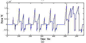 Figure 10: The Total EV Power Load for: (a) UDDS, (b) NYCC, (c) Japan1015 drive cycle
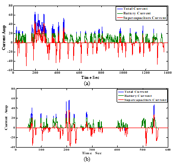
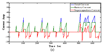 Figure 11: The limit R-B LQR HESS currents for: (a) UDDS, (b) NYCC, (c) Japan1015 drive cycle
On the other hand, Figure 12 shows the share limit R-B LQR response currents of HESS for the UDDS, NYCC and Japan1015 drive cycles. In the share limit R-B LQR algorithm, the battery and supercapacitors were shared to supply the load current for the EV and the battery current limited by Ib_max 20A. The battery supplied 70% from the load current, while the supercapacitor supplied 30% from the load current. Furthermore, the supercapacitors absorbed all the regenerative current during the deceleration and braking. The sharing load current and the limitation of the battery current lead to a reduction in the battery stress of the EV, and extended the number of possible cycles.
 Figure 12: The share limit R-B LQR HESS currents for: (a) UDDS, (b) NYCC, (c) Japan1015 drive cycle
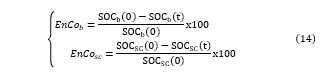 Equation 14 represents the calculation of energy consumption for the battery and supercapacitors.
Figure 13 illustrates the state of charge of the battery for the proposed controllers of HESS, and battery only for UDDS, NYCC and Japan1015 drive cycles. In the battery only scenario, the battery supplies the total load of the EV, and the energy consumption (EnCob) for UDDS, NYCC and Japan1015 drive cycle is 8.3%, 1.3% and 2.6% of the total stored energy of the battery respectively. In the limit R-B LQR controller of HESS, the energy consumption from the battery for UDDS, NYCC and Japan1015 drive cycles is 6.7%, 1.15% and 2.3% of the total stored energy of the battery respectively. Meanwhile, in the share limit R-B LQR controller of HESS, the energy consumption from the battery for UDDS, NYCC and Japan1015 drive cycles is 5.37%, 0.95% and 1.79% of the total stored energy of the battery respectively.
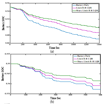
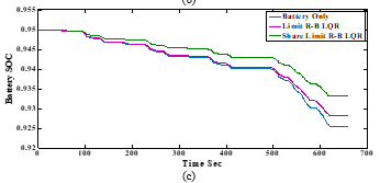 Figure 13: The battery stat of charge for: (a) UDDS (b) NYCC (c) Japan1015 drive cycle
The state of charge of supercapacitors increased during the operation, after absorbing the regenerative energy. In the limit R-B LQR controller of HESS, the energy earned in the supercapacitor for UDDS, NYCC and Japan1015 drive cycle is 18%, 14.5% and 12.7% of the total stored energy of the supercapacitors respectively. In the share limit R-B LQR controller of HESS, the energy consumption in the supercapacitor for UDDS is 16.4% and the energy earned in the supercapacitor for NYCC and Japan1015 drive cycles is 9.1% and 0.0% of the total stored energy of the supercapacitors respectively. Figure 14 presents the state of charge of the supercapacitor for the proposed controllers of HESS, for the UDDS, NYCC and Japan1015 drive cycles.
 Figure 14: The supercapacitors stat of charge for: (a) UDDS (b) NYCC (c) Japan1015 drive cycle
The design of the R-B LQR controllers achieved a wide range of operating zones for the supercapacitors. Moreover, the results of the supercapacitors state of charge proved that the supercapacitors work continuously during the drive cycles. Table 2 summarizes the state of charge of the battery and supercapacitors, the energy consumption of the battery and supercapacitors, and the number of possible cycles for the UDDS, NYCC and Japan1015 drive cycles. The results indicate that the share limit R-B LQR controller extended the n number of drive cycles compared to limit R-B LQR controller, with same battery size and supercapacitors.
The limitation of the proposed share limit R-B LQR algorithm is that the energy sharing percentage between the battery and supercapacitors is fixed to 30%, which leads to discharging the energy of the supercapacitors quickly in case the regenerative energy was limited. Future work will consider optimization algorithms to obtain the optimal value of energy sharing between the battery and the supercapacitors.
Table 2: The Battery and supercapacitor state of charge for three different standard drive cycles
| HESS | UDDS | NYCC | Japan1015 | |
| Battery Only | 0.95 | 0.95 | 0.95 | |
| 0.871 | 0.937 | 0.925 | ||
| 8.3% | 1.4% | 2.6% | ||
| 9 | 53.6 | 28.8 | ||
|
HESS with Limit R-B LQR |
0.95 | 0.95 | 0.95 | |
| 0.886 | 0.939 | 0.928 | ||
| 6.7% | 1.15% | 2.3% | ||
| 0.55 | 0.55 | 0.55 | ||
| 0.65 | 0.63 | 0.62 | ||
| -18% | -14.5% | -12.7% | ||
| Cycles No | 11.2 | 65 | 32.6 | |
|
HESS with Share Limit R-B LQR |
0.95 | 0.95 | 0.95 | |
| 0.899 | 0.941 | 0.933 | ||
| 5.37% | 0.95% | 1.79% | ||
| 0.55 | 0.55 | 0.55 | ||
| 0.46 | 0.60 | 0.55 | ||
| 16.4% | -9.1% | 0% | ||
| Cycles No | 12 | 79 | 42 |
- Conclusion
This work proposed a control strategy for the battery-supercapacitors Hybrid Energy Storage System for an Electric vehicle. The state-space average model was used to analyze the dynamic behavior of the DC-DC converter. Two R-B LQR algorithms were proposed to manage the current flow in the HESS. The battery and supercapacitors responses was investigated with three different standard drive cycles, namely, UDDS, NYCC and Japan1015. The simulation results demonstrate that the limit R-B LQR has the ability to limit the battery current of HESS to Ib_max , in different types of drive cycles. Moreover, the proposed share limit R-B LQR was successful to limit the battery current and extend the number of possible drive cycles. The proposed algorithm enhanced the battery life-cycle and the stability of the energy storage devices, and effectively reduced battery sizes.
Conflict of Interest
The authors declare no conflict of interest.
Acknowledgments
The presented research was supported by Universiti Tunku Abdul Rahman Research Fund (UTARRF) under research Project Number IPSR/RMC/UTARRF/2015-C1/C05 and KL Automation Engineering Sdn Bhd.