Switching Capability of Air Insulated High Voltage Disconnectors by Active Add-On Features

Adv. Sci. Technol. Eng. Syst. J. 6(1), 43–48 (2021);
 DOI: 10.25046/aj060105
The need of add-on features (secondary contacts) for current paths of air insulated high voltage disconnectors switching capabilities (e.g. bus transfer switching) is introduced. The relevant product components for the switching capability and their functionality is described, which is giving boundary conditions for adding features necessary to achieve the switching capability. Possible features are discussed with necessary properties and performance. Those are separated in passive and active solutions, which are focused. Given solutions successfully applied, are explained and capabilities are shown based on experimental design and testing – where calculations and/or computational analysis are not shown (consequently no resulted data of such approaches), as those have not been used for the given solutions (the disconnector is still a low-cost product within industrial business circumstances, where invests for comprehensive design activities are unfortunately very limited). The testing of the solutions is covered with information for limited switching capability values and measures and/or further, partially theoretical, alternative solutions, for increased values. Also, the testing itself and possible laboratories with certain test execution opportunities and/or challenges is elaborated. The conclusion provides a market view, product users perspectives, in regards of the applicability for passive solutions and the need for active solutions.
1.Introduction
This paper is an extension of work originally reported in Proceedings of the International Conference on High Voltage Engineering and Technology (Central Power Research Institute, India) [1].
The standardized minimum switching capability of air insulated high voltage disconnectors (negligible currents of 0.5 A for rated voltages up to 420 kV as per IEC 62271-102) [2, 3] is frequently exceeded by three main applications:
- no-load conditions of transformers (inductive)
- long high voltage conductors (overhead lines, capacitive)
- bus-transfer cases within substations with more than one bus bar
The bus bar transfer case, being very common, is standardized by the IEC 62271-102, where the latest edition partially considers increased values (bus-transfer voltage and current) [2, 3].
A disconnector in its standard configuration will not be able to switch exceeded values. The damages on the contact system (contact erosion) would be too high to be still operational after such a switching case. The application of add-on features is necessary (secondary contact arrangements, like additional contact fingers), so that the contact system is protected and accordingly switching capabilities are achievable. Those add-on features are design as passive and/or active secondary contact arrangements [4-9].
The Main difference of the passive and active solutions is driven by the operational speed, where passive solutions are fully dependent on the current path design and active solutions are integrating semi or full independency of the current path design.
2. Current Path Operation
2.1. Current Path Types
The disconnector type determines the current path outlining (shape). The known types are groupable in inline disconnectors (the center break, the double side break, the side break, the V-type (based on center break or double side break disconnectors), the vertical break and the knee-type disconnector) and busbar disconnectors (the vertical reach, the semi-pantograph and the pantograph disconnector).
For the inline disconnectors the current path operation occurs horizontally, and a common secondary contact arrangement solution can principally be achieved. For the busbar disconnectors the current path operation occurs vertically – a common secondary contact arrangement is not known to be achievable [4-9].
For the busbar disconnectors, the vertical reach and the semi-pantograph are likely to share a secondary contact solution with their familiars of the inline group (vertical break and knee-type respectively).
The pantograph disconnector is very unlikely to achieve a common secondary contact solution with one of the other mentioned disconnector types – its design principal of the current path is too distinctive.
2.2. Current Path Opening and Closing
Disconnectors are only operational under no-load conditions. The requirements for switching capability are given by residual currents, consequently main contact systems are designed for static current carrying capabilities [1-9].
In order to protect the main contact system (carrying rated continuous currents and short-circuit currents) it is necessary for any secondary contact arrangement to run ahead of the main contact system while the closing operation and to go behind the main contact system while the opening operation of the current path.
This is essential for the protection purpose, as the switching capability in any case results in arcing (lightning) and accordingly arc erosion resistance requirement. An optimized contact system in regards of the main purpose of carrying current will not be able to sustain such arcing erosion, where the main purpose of the secondary contact arrangement is this resistance but will not be suitable for carrying current continuously.
3. Secondary Contact Types
Where the main contact is optimized for low resistance (best current carrying capability while minimized losses, heating or hot spots) and longest lifetime, the secondary contact needs optimization for high resistance and a minimum lifetime (considering the IEC 62271-102 or specific market/customer requirements) [1-9].
Striving for this, the main contact needs:
- To be decoupled in switching operation conditions of the disconnector for being save from damages by arcing (lightning).
- A contact pressure suitable for the current carrying capability, but as small as possible for friction avoidance (no-load operations).
- A material choice suitable for the current carrying capability, but a surface supporting lowest friction (no-load operations).
Usually this results in silver plated copper fingers with applied springs to achieve the necessary contact pressure – being still one of the most economic solutions. Highly controlling the elasticity of the used copper may allow spring elimination but is likely to require silver-graphite-plating (increasing lubricating properties, decreasing friction), which again is more costly due to the manufacturing process efforts.
The secondary contact needs:
- To be decoupled in normal operation conditions of the disconnector for being save from damages by rated continuous currents or short-circuit currents.
- A contact pressure suitable for the switching capability – residual currents need to be carried safely, so that arcing on the main contact cannot occur. Additionally, considering certain numbers of switching operation and occurring erosion, the chosen contact pressure needs to overcome accordingly outline changes (reduction) of the contacts (sacrificial contacts) – preventing jumping or bouncing effects of the secondary contact and any arc-back (reigniting) due to contact separation.
- A material choice suitable for the arc erosion resistance (residual currents)
In dependence of the secondary contact solution, the material choices vary significantly – again under economic aspects, so that any material usage is minimized as much as possible in regards of the used solution.
Used names for known solutions like arcing horn, guiding horn, bus-transfer device or filter-switching device are not used. Those are given mainly by the reasons for occurrence of the residual currents to be switched and are not reflecting the common task [1].
3.1. Passive Secondary Contacts
Passive solutions, depending fully on the operation speed of the disconnector, require materials with high arc erosion resistance. Material suitability is firstly indicated by a high melting point and a high tensile strength, nevertheless the tensile strength of a material is sometimes significantly reduced when heated (even far below the melting point). Tungsten, the element with the highest melting point of the periodic table of the elements, is a proven choice.
Market availability (raw material, alloys, machinability) and implied material costs is another important factor.
Finally, the resistance to corrosion and the conductibility is still of importance, so that mostly copper alloys will be used and respectively proportions needs to be defined. Further optimized material usage will be achieved by inlet applications and possible conductive connection methods need to be considered for the material choices, as well.
Reported application examples have been [1]:
- Passive add-on finger – a copper zirconium alloy finger with a copper tungsten alloy inlet and a copper tungsten alloy stud (high tungsten content – more than 3 quarters of the alloy experienced to be necessary of tungsten)
- Passive add-on needle – copper zirconium alloy crossbars with copper tungsten alloy inlets and ‘tungsten needle’
The examples also successfully applied zirconium, which is another high-melting point element with a high enough tensile strength, also heated. Principally the noble metals are potential candidates: Ruthenium (Ru), Rhodium (Rh), Osmium (Os), Iridium (Ir), Zirconium (Zr), Hafnium (Hf), Vanadium (V), Niobium (Nb), Tantalum (Ta), Chromium (Cr), Molybdenum (Mo), Tungsten (W), Rhenium (Re) and Technetium (Tc).
3.2. Semi-Active Secondary Contacts
Passive secondary contact may be enhanced by detailed design features for generating air flows advantageous for reducing the arcing time, so to increase the possible switching quantity or increase the switching capability.
For this, the air flow needs to be directed to one of the foot points of the arcing (inception point or arc origin), so that the separation or arc interruption will be facilitated. The enhancing effects are limited, but a significant advantage is the minimum weight effect for consideration of the mechanical behavior of the current path.
One successfully applied example is shown in figure 1, where a simple synthetic material could significantly increase the capability withstanding heating sufficiently.
 Figure 1: Example of Air Flow Controlling Detailed Feature
The controlled air flow is not only forced into the right direction towards the arcing foot but is also determined for volume and speed by the given passage. As the success was experimental, the air flow details have not been measured, but the switching current was more than doubled (form 6 A to 15 A) at the same switching voltage (21 kV). The achieved switching current was limited by the used laboratory, so that the capability limit of the solution could not be determined.
The finger outline (knife type) allows a relatively long air flow controlling item and therefore passage, which is important for determining the speed of the used volume. The passage is generated as a cuboid-like channel between the detailed design feature and the secondary contact finger by the fixation solution of the feature on the finger. The applicability depends highly on the outline of the used secondary contact, so that the shown example is limited in its applicability accordingly.
Further it represents rare occasions, where the type test execution allowed contractually a limit testing (in this case limited by the laboratories capabilities). The usual situation, as valid for all other shown cases, is a design and testing as per standard and its required values to be fulfilled (mainly IEC 62271-102 [2] or specific customer requirements).
3.3. Active Secondary Contacts
Full active secondary contacts will be designed with elements storing kinematic energy, which is released when required and provide the independent speed – classically those elements will be springs [5-9].
Figure 2 shows an example of such an active secondary contact. Compared to known passive contact systems it could be validated, that the switching capabilities are achievable with using only classical materials – the using of high-melting point materials or accordingly copper alloys was not necessary.
 Figure 2: Active secondary contact system (double side break disconnector)
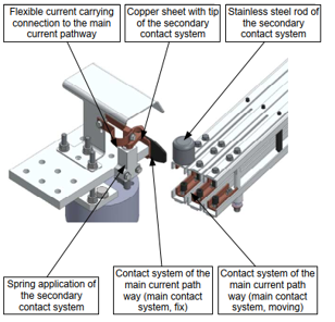 Figure 3 shows the same example of such an active secondary contact at a position of the closing operation, where the secondary contact is ahead of the main contact system. The copper sheet needs to run over the stainless-steel stud, so that the secondary contact goes behind the main contact system while the opening operation.
Figure 3: Feature Active secondary contact system in ahead-position
The spring is effectively applied only while the opening operation, so that the kinematic energy is specifically used for the demolition of the arc.
The intensity of the arc erosion while the closing operation is of much lower severity – as the arc arises, while the arcing distance decreases steadily. The arcing time is generally lower and the arc erosion stress on the foot points is less. In contrary, the erosion while the opening operation is of much higher severity – as the arc arises, while the arcing distance increases steadily until a high enough distance for insulation by air is achieved. In dependence on the arc intensity (voltage and current) the arcing time is maximized in relation to the air gap necessary for demolition – exactly here the spring application comes into effect. Where passive solutions need to withstand this to full extend (only minimizable by dimensioning and eventually material elasticity), active solutions can significantly reduce the time independent speed. Of course, also active solutions require right dimensioning, as the used spring energy needs to fit to the allowed arcing time – achieved air gap at the time of arc ignition.
The spring application of active solutions does not require high-melting point material, which avoids the before mentioned challenges in regards of market availability. This allows again the usage of general core activities of disconnector designer and supplier concerning the current paths – plated copper / contact systems with spring applications.
Additionally, secondary contacts can be equipped with air flow controlling detailed feature. The shown example of figures 1 and 2 gives only little room for this.
3.4. Medium Voltage Switching Units
A further possibility for highest switching capabilities is given by the application of medium voltage switching units for active secondary contact systems. Those can be SF6 switching units or vacuum switching units, where the latter one is by far the preferred one as the first one is getting banned already in certain markets due to its negative environmental effects. Such a unit provides the advantage that in case of closing operations being kept open, no lightning occurs (because of the gap in the chamber of the unit). Important considerations of the application:
- Need for short-circuit resistivity in regards of the disconnector application
- Weight implications for the mechanical operation behavior of the current path – especially if applied to the moving part
- Potential requirement for complex kinematics for the operation of such units (tensioning and releasing unit internal spring applications)
- Protection of such units against environmental effects (e.g. rain or ice) with housings
The so far reported solutions (passive and active) are providing the big advantage against potential switching units application, that the weight implications is only low or eventually moderate and that the environmental protection coverage is mostly already given by the accordingly protection of the main contact system (or by simple and small size increase of the same).
The following earthing switch examples (figures 4 to 6) show known and successfully applied medium voltage switching units, which provide a technical basis being transferable to disconnectors.
 Figure 4: Earthing Switch Application with SF6-Switching-Unit (switching capability beyond class B as per IEC 62271-102)
 Figure 5: Earthing Switch Application with Vacuum-Switching-Unit and Arrester (switching capability requirement without lightning fulfilled)
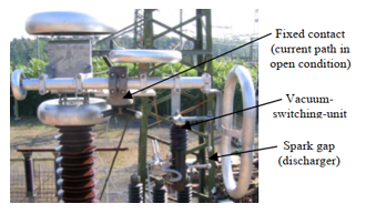 Figure 6: Earthing Switch Application with Vacuum-Switching-Unit and Spark Gap (switching capability requirement without lightning fulfilled)
4. Values and Testing
In practice, as well as per IEC 62271-102, type test confirmations are possible and common [2,3].
Regarding passive secondary contacts a confirmation of the type test for the same type of disconnector is physically evident for increasing disconnector sizes (higher rated voltages), as the arm length of the current path increases and therefore the angular speed increases. This provides beneficial conditions for the secondary contact as the arcing time gets reduced the reference type test is safely applicable. The same is difficult for decreasing disconnectors sizes by reduced current path arm length and consequently reduced angular speed and increased arcing time. Even with the proven margin within a type test, the applicability is not secure. Such kind of confirmation challenges will be increased by changing the disconnector type.
For active secondary contacts the confirmation situation is much more convenient based on the independent speed. The applicability or validity of successful type tested active secondary contact is evident based on the positioning of the secondary contact elements for their function and in relation to the main contact system (protection purpose) in accordance to the reference type test. The disconnector operational speed is not relevant. This is another important advantage of active solutions.
4.1. Switching Capability Values
The reported solutions are classical solutions and followed the edition 1 of IEC 62271-102. Therefore, the switching capability target was usually set to a switching current of 1600A, the limit given with the rule for 80% of the rated continuous current. Further, the switching voltage was mostly set to 100V, as most of the market requests have been served with accordingly rated voltages (up to 170kV as per edition 1 of IEC 62271-102, but often also for higher rated voltages based on customer acceptance). The reported example of an active solution followed this approach, as it was achieved before the release of edition 2 of the IEC 62271-102 [2,3].
Since edition 2 of IEC 62271-102 [2], the general limit of 1600A is only applicable for rated voltages <245kV. For rated voltages of ≥245kV and ≤550kV, the limit is set to 4000A, which is a significant increase in arcing intensity for the switching capability (even though the percentage approach was reduced to 60%). Further, the switching voltage required is not only based on ranges of the rated voltage, but additionally dependent on the rated continuous current [2, 3].
Following an approach to design a solution for covering a major part of the values with this given current scenario is very difficult, if not impossible with passive secondary contacts. Latest for rated voltages of 245kV and above this will require active secondary contacts, as those provide higher capabilities – beside the advantageous confirmability.
4.2. Test Circuits and Laboratories
Edition 1 of IEC 62271-102 requested a power factor of 0.15 for the test factor and certain conditions for the transient recovery voltages, where the edition to requires a power factor of 0.5 and skipped the part for the transient recovery voltages. On the maintenance for at least 3s after interruption of the power frequency recovery voltage is no change between the editions of IEC 62271-102 [2, 3].
In fact, this is reducing the arc intensity for the type test. However, first experiences indicate that this is far not enough for having passive secondary contacts capable to achieve the before mentioned approach on switching capability values [7-9].
Basically, high power laboratories are providing equipment for testing the switching capabilities of air insulated high voltage disconnectors. The following restrictive points for the test execution of disconnectors must be carefully aligned with such potential laboratories:
- Space constraints – as disconnector test objects easily lead to high installation space necessary, specifically with increasing rated voltage of the test object. Ground fixation can be a challenge regarding the typical outline of a disconnector, which is potentially unusual for the equipment tested in the concerned laboratory. The installation height is another specific aspect of a typical disconnector outline with potential high challenge for the concerned laboratory
- Where the switching current to be tested is generally unproblematic for high power test laboratories, the switching voltage to be tested has carefully to be checked with the laboratory. This is even more stressed regarding the required values for high rated continuous currents following the IEC 62271-102 edition 2 [2] (identifying a high voltage laboratory with capabilities for the switching currents to be tested is very unlikely).
- The time necessary for the test execution is an important factor, as well. As such tests are usually not the core business of accordingly laboratories, the necessary slot size by time needs carefully to be aligned – the laboratory utilization, the throughput of test quantities, will be significantly impacted. The main determination of the overall test execution time is not mainly given by the quantity of operations to be done, but by the necessary time between to operations. This can be called cooling time and has to be determined by the disconnector designer/ supplier. Classically the focus was given by the avoidance of a motor overload (operating mechanism of the disconnector, automated test execution), which is with nowadays’ motor performances not an issue. In fact, the focus needs to be given to the heating of the secondary contact – pre-heated secondary contact in view of subsequent operation. A maximum time gap between 2 operations is not regulated by standards and a realistic occurrence in the field will not be within minutes (maybe within days). For the before mentioned passive solutions a minimum time gap of 2 minutes was found to be enough (based on the high-melting point element tungsten). Considering 100 necessary operations (IEC 62271-102) [2], this ends up already to 3 hours, where setting, operation and frequent visual inspection has to be added, so that this part of the test execution easily need already a full day
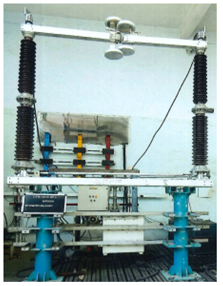 Figure 7: Switching Capability Type Test Set-Up of a 245kV Center Break Disconnector with a Passive Add-On Finger Solution
Market demands represented in standards or resulting in new versions of standards are especially in the case of IEC globally driven. Based on this the possible design realization may be given already, but not generally. Usually it will be left to suppliers and customers to foster such realization, which will require consideration and alignment with testing facilities for realizations of accordingly type tests. The basis will be for the supplier, as well was for testing facilities, positive economic value adds. Potential volume, utilization and market prices will need to provide a minimum basis for judging accordingly efforts. Partially even the requesting customers will join in a collaborative approach covering certain costs for realization (invests on disconnector supplier and/or tasting facility sides).
The switching capability testing for air insulated high voltage disconnectors could already be executed successfully with medium voltage high power laboratories (refer to figure 7). On first view this seems to be unusual but was possible since the above restrictive points have been servable.
5. Applicability Conclusion
As in every case of significant changes in standards and regulations there will be a transition period before the market will strictly insist. The established secondary contact solutions for the switching capability realization will therefore persist on the market for a certain period.
The market is already demanding steadily increased rated continuous currents, which is also reflected by the edition 2 of IEC 62271-102 [2], but not comprehensively. This is fostering the increased switching capabilities reflected in the edition 2 of IEC 62271-102 [2], but accordingly market demands run after the rated continuous current demands.
5.1. Passive Solutions
The shown examples are well suitable and proven especially for the rated voltage application <245kV, also in regards of the second edition of IEC 62271-102 [2]. Nevertheless, those solutions are at its limits and may exceed the given capabilities by semi-active detailed features. It requires the management of high-melting point elements for the design and the purchasing.
Consequently, it is reasonable that those passive secondary contact solutions will experience a replacement by simple active secondary contact solutions (e.g. the one reported above), as those allow increased switching capabilities and the avoidance of high-melting point elements.
5.2. Active Solutions
It is expected that active solutions will be the common solution in the feature based on the potentials given above – specifically in case of simple material usage and spring application, as reported above.
Considering the highest switching capability requirements as per edition 2 of IEC 62271-102 [2] – for the highest rated voltages and rated continuous currents – a strong demand for solutions integrating medium voltage switching units (chambers) is expected. Taking into account typical examples of bus-transfer disconnectors, like the pantograph disconnectors, and accordingly expected switching capabilities requirements as per IEC 62271-102 [2] or even above based on customer requirements, it is unlikely to be achievable with kinds of simple active solutions without compromising on functional reliability.
Vacuum chamber applications to the mating contact of pantograph disconnectors of 420kV rated voltage are under investigation and a final design achievement will need to be proven by type testing.
5.3. Earthing Switch Solutions
Earthing switches by its design and purpose must consider distinctive switching capabilities against disconnectors. Already accordingly standards are covering those switching capabilities reasonably distinctive [1-3].
Introduced earthing switch references with passive, active or active solutions considering medium voltage switching units are to be discussed separately. Basically, those known and successfully applied solutions are transferrable to disconnectors, but need specific considerations – e.g. the current path of an earthing switch is not having any duty of carrying rated continuous current, where this is one of the main duties of the current path of the disconnector (also this underlies exceptions for the earthing switch for certain applications) [1-9].
Conflict of Interest
The authors declare no conflict of interest.
Acknowledgment
Mariusz Rohmann thanks his wife Nallely Dzib Soto for her patience and continuous support while his professional efforts and specifically responsibilities and commitments abroad on delegations.
Mariusz Rohmann thanks Guru Moorthy Kurra for his collaboration, teamplay and continuous support while his delegation to India (April 2018 to January 2020) and up to today within his professional responsibilities and tasks.
- M. Rohmann, D. Schräder, G. Kurra, S. Challa, S. Mogatala „Swicthing Capability of Air-Insulated High Voltage Disconnectors”, IEEE, 2019, ISBN 978-1-5386-7577-9/19
- IEC 62271-102, High-voltage switchgear and controlgear – Part 102: Alternating current disconnectors and earthing switches, Efition 2.0, 2018.
- IEC 62271-1, High-voltage switchgear and controlgear – Part 1: Common specifications for alternating current switchgear and controlgear, Edition 2.0, 2017.
- CIGRE Technical Brochure No. 511: Final Report of the 2004 – 2007 International Enquiry on Reliability of High Voltage Equipment, Part 3 – Disconnectors and Earthing Switches, 2012
- S.S. Rao, “Switchgear Protection and Power Systems (Theory, Practive and Solved Problems)”, Khanna Publishers, 2008.
- M. Rohmann, “Analysis of Assembly Times for a Gas-Insulated High Voltage Switchgear on the Level of Components”, M. Sc. Thesis with Siemens AG at FernUniversitaet Hagen, 2008.
- H. Lindner, Dr. Harry Brauer, Prof. Dr. Constants Lehmann, “Pocket Book of Electro-Technics and Electronics”, Fachbuchverlag Leipzig, 1999, ISBN 3-446-21056-3.
- G. Balzer, Bernhard Boehle, Kurt Haneke, Hans Georg Kaiser, Rolf Pöhlmann, Wolfgang Tettenborn, Gerhard Voß, „Substations“, 9th ed., Cornelsen Verlag Schwann-Giradet Duesseldorf, 1992, ISBN 3-464-48233-2.
- Prof. Fleck, P. Kulik, “High and Low Voltage Substations”, Verlag W. Girardet Essen, 1975, ISBN 3-7736-0262-6.
No related articles were found.