Surge Protection Device for Ex Application

Adv. Sci. Technol. Eng. Syst. J. 5(6), 768–780 (2020);
 DOI: 10.25046/aj050692
A modern process plant is controlled, operated and safeguarded by the sophisticated distributed control system or a programmable logic controller and an emergency shutdown system. This process plant’s operation could be seriously affected by lightning, electrical switching, and power outrage. Lightning propagation can travel kilometers away, which has the risk of disturbing the control system’s operation. The process plant’s control system could damage when it is subjected to surges induced by lightning, power outrage, or heavy load switching. To protect equipment damage from these surges surge protection device is required. A number of the process plant uses flammable material for its production or during the manufacturing processes, explosive gas or vapor is released created an explosive atmosphere known as hazardous (Ex) area. Surge protection device mounted in the Ex area or used in the Ex control loop needs to be carefully selected to protect the equipment and at the same time, it does not become a source of ignition. This paper provides practical consideration and comprehensive detail in revealing the science and engineering behind Ex application on surge protection devices. The technical presentation is limited to equipment protection; structural protection against lightning will not be discussed here.
1. Introduction
This journal article is an extension of the original conference paper entitled, “Practical approach on surge protection device for Ex application,” presented in 2019 1st. International Conference on Electrical, Control and Instrumentation Engineering (ICECIE), Kuala Lumpur, Malaysia [1].
Lightning is a natural phenomenon that can be seen in volcanic eruptions, pyrocumulonimbus clouds, heavy snowstorms, hurricanes and thunderstorms [2]. Lightning-induced voltage surges can enter into the electrical system via the capacitive, inductive and resistive coupling [3]. According to the report from NFPA [4], in the United States alone, from 2007 to 2011, an estimated 22,600 fire cases were caused by lightning, with a $451 million loss in direct property damage per year. The report also cited several explosion incidents caused by the lightning surge. One of them is a coal mine (Ex area) explosion in January 2006 in West Virginia, which claimed 12 lives. A protective circuit like a surge protection device or SPD is used to protect the electrical apparatus and its accessories from the damage created by transient surge activity induced by the lightning and surges generated by switching heavy reactive load or power supply interruption and prevent a fire. SPD has to be carefully selected and with proper installation for its intended function; else, instead of preventing equipment failure, it could become the source of fire or explosion as reported by [5–7].
In the original paper, the following are either not evaluated, missing or too brief as the reader is expected to have the background knowledge to understand the subject. In the present work, the critical area left out by the original paper is being addressed and enhanced. The rectification and enhancements are highlighted below:
- The reasons why SPD is needed for the modern electronics system for the application in a safe, hazardous area and critical control loop application.
- Why is the selection criteria on SPD for safe area application not sufficient for hazardous area application?
- Presentation on the lightning protection zone (LPZ) and the SPD types are too brief on the original paper. Therefore it is decided to separate them into two sub-sections with enhancement and with an application example. Definition and a summary of the key points are also being addressed and tabulated.
- Application on lightning protection level’s (LPL) concept; what needs to be done before implementing LPL and the efficiency level for various LPLs are added.
- The description of the maximum continuous operating voltage has been revised to reflect the practical application.
- The illustration on the concept of the “Temperature Classification” is enhanced with a practical example.
- Elements required to be present for an explosion to occur and the concept of various explosion protection techniques being implemented are added.
- Using “Spark Test Apparatus” to obtain the minimum ignition curve for inductive, capacitive and resistive load at the field. The application of the minimum ignition curves is also added.
- Requirement on the hot permit to carry out maintenance and typical application example is added for flameproof, Exd protection.
- Hot surface investigation and typical applications example for increased safety, Exe protection is added.
- Missing entity safety parameter description on the cable capacitance and inductance for intrinsic safety, Exi protection technique is rectified.
- Surge withstanding capability (SWC) consideration is added as it is missing in the original paper.
- Why are two SPDs needed for a control loop? Why one of the SPD will have the Temperature Classification, the other one is not necessary?
The subject of explosion protection for industrial automation applications (non-military) is a specialist field; hardly any higher education institution conducting the courses. Hence, most of the knowledge on various explosion protection technique is coming from the industry. There are very few industry players who produce multiple Ex-rated products and conduct multiple Ex-product research; most of the manufacturer only specialist in their respective areas of expertise. For example, field device manufacturers (field devices like pressure transmitter, I/P converter, control valve, solenoid valve, etc.) like Honeywell, Emerson or Yokogawa only produce Ex-rated field devices, not other devices like Ex-rated junction box or cable gland. Therefore it is difficult for the industrial user to familiarize themselves with various explosion protection techniques for all the control components. This paper helps the industrial user to implement surge protection in the Ex area systematically. It investigates and evaluates the selection criteria and SPD’s application requirement for Ex area application with various explosion protection techniques. Safety calculation and proper installation are also presented. It details down all factors involved in implementing the solutions. Two application examples are quoted in detail.
The paper starts the discussion on the need for the SPD in the modern electronics system in the safe area, hazardous area and the critical control loop application; The working principle of the SPD then moves on to the selection criteria for Ex applications and the common explosion protection technique that could be applied together with SPD. Three explosion protection techniques are selected for evaluation and discussion in detail on its application, namely the application of SPD using Exi (intrinsically safe), Exd (flameproof) and Exe (increase safety) protection method in the common explosion protection technique section. The paper then provides two working examples of how the selection and application of SPD using Exi and Exd methods. Safety parameter calculation, distance requirement, temperature consideration, etc., are presented in the examples. The paper ends with a summary of the key area of consideration and criteria in selecting the SPD for Ex application.
2. Why Is Surge Protection Important In The Modern Electronics System?
Modern equipment demands for more application features, faster speed, smaller physical dimensions and lower power consumption. This makes the circuit designer squeeze more transistors into a smaller IC chip, using the material to operate at a lower voltage and lower power consumption. The progress in developing faster, denser and lower power consumption IC Chip makes the modern electronics circuit more vulnerable to the induce transient surges than the early components that use vacuum tube and discrete transistor. Hence, transient surge protection is becoming more important in the modern electronics system. Figure 1 shows the increase of equipment failure rate from the early vacuum tube technology to the modern IC chip caused by transient surges.

Figure 1: Increased Rate of Equipment Failure [8].
On the other hand, modern electronic systems also rely a lot more high-performance electronic components to execute the critical task that cannot afford to fail. Failure will lead to plant shutdown and production losses, which will cost millions of dollars. For example, emergency shutdown systems (ESD), depending on the process and the safety requirement, can be designed as a standalone, redundant system or triple redundant system to cope with equipment failures. A redundant design plus a logic solver algorithm allows the ESD to detect the real loop failure and decide when to shut down the plant using the voting system. Once the decision is made, the plant is then shut down according to the pre-determined sequence to avoid plant accident or explosion. The redundancy is often achieved by duplicating or triplicating the field sensor, input-output cards, control processors and even the actuators. Almost all the field sensors, except for the wireless system, are connected to ESD by cables, potentially entry routes for the transient surges. Therefore, SPDs are included in the system design to improve the resilience of such systems from the effect of transients.
When a process plant uses flammable material for its production or during the manufacturing processes, explosive gas or vapor is released created an explosive atmosphere known as hazardous (Ex) area. SPD mounted in this Ex area needs to be carefully selected to protect the equipment from transient surges and at the same time, it does not act as a source of ignition. SPD requirements for the hazardous (Ex) location are often more stringent than in the non-hazardous (non-Ex) locations.
When sizing up the SPD for equipment protection for safe area application, generally, the let-through voltage (should be below the SWC [9–11] of the device to be protected), kA rating, connection method (either series or parallel) of the SPD need to be considered. However, when the application is involved with the Ex area, this is not sufficient as the SPD could become the source to initiate an explosion. The additional consideration for the SPD to use in the Ex area includes the SPD’s mounting location, the applicable explosion protection technique, equipment surface temperature, and equipment heat dissipation.
3. Working Principle of SPD
SPD protects the electrical installation, consisting of electrical equipment, consumer unit, wiring and accessories, from electrical power surges known as transient overvoltage. The lightning activity, electricity is interrupted and immediately re-established or the switching of a heavy reactive load could instigate the power surge. Figure 2 illustrates the working principle of a 4-20mA signal line SPD. When there is no transient surge, the SPD does nothing; it is transparent to the circuitry. Whenever a surge appears, the SPD will be triggered instantly. It clamps the SPD’s output voltage, depending on the model used, to a pre-determined level and diverts all the excessive current to the ground via a protective earthing terminal.
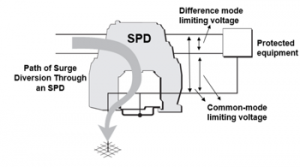
Figure 2: Working Principle of a signal SPD (redrawn from [1] with additional information).
4. Selection Criteria on SPD for Ex Area Applications
When selecting an SPD for use in the Ex area, all the selection considerations and criteria on SPD for the safe area application are applied. Additionally, all other factors that could cause the SPD to trigger an explosion and other ignition sources should be considered as well.
Typically, SPDs are mounted in a panel at the control room to protect the systems and its component against surge. If there is a requirement to protect the field device from surge, additional field mounted SPDs will be required. In other words, the process control loop will require two SPDs. One SPD is mounted as close as possible to the field device (to protect the field device), another one should be mount as close as possible to the controller (to protect the controller) at the control cabinet.
4.1. Types of SPDs
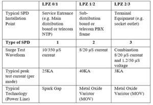
IEC 61643-11:2012 and NFPA 79 standard defined three different types of surge protection devices (SPDs). They are Type 1, Type 2 and Type 3, respectively. The SPD types provide information on where an SPD may be installed, as shown in Figure 3. The energy discharged from the surge is brought down in various stages, starting with the more robust SPD (Type 1) and finer protection Type 2 and Type 3 SPDs. This protection arrangement and co-ordination are represented with the Lightning Protection Zoning (LPZ), which divides the structure based on the lightning strike effects.

Figure 3: Types of SPD and Its Mounting Location. [12].
Type 1 SPD: Provide lightning protection against transient overvoltage instigates from direct lightning strokes where the lightning discharge voltage could spread from one of the structures earth conductor to the other network conductors. Type 1 SPD is characterized by a 10/350μs surge current waveform per IEC 61643-11:2012
Type 2 SPD: It is the primary protection system for low voltage electrical installations. Protect against transient overvoltage caused by switching or indirect lightning strokes. Typically, it is installed in the electrical distribution board (DB) to prevent transient surges in the electrical installations and protect the loads. Type 2 SPD is characterized by a 8/20μs surge current waveform per IEC 61643-11:2012
Type 3 SPD: Type 3 SPD is aimed to provide local protection on sensitive and critical loads. This SPD has a low discharge capacity. It is only installed as a supplement to Type 2 SPD and it is installed as near as possible to the sensitive loads. They are widely used as hard-wired devices and generally combined with Type 2 SPDs for fixed installations. In many cases, they are built-in and incorporated into a surge-protected socket outlet, surge-protected portable socket-outlets for telecommunication lines and data protection. Type 3 SPD is characterized by a combination of voltage waveform (1.2/50 μs) and current waveform (8/20 μs).
Table 1 provides a summary of Types of SPD, its test waveform and the current rating, as well as the typical technology used and the Lightning Protection Zone (LPZ). LPZ will be discussed in the following section.
Table 1: Types of SPD, Test Waveform, Applicable Technology and LPZ [13].
4.2. Lightning Protection Zone, LPZ
IEC 62305-4:2010 describes the LPZ concept. LPZ identifies and divides a structural area according to the risk level exposed to the Lightning Electromagnetic Impulse (LEMP). It coordinates the type of SPD’s kA current rating requirement within the zone. The concept of LPZ taken from IEC 62305-4: 2010 is as shown in Figure 4. ANSI/IEEE C62.41 also has a similar concept, as shown in Figure 5.
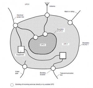
Figure 4: The Principle of LPZ – Division into Different LPZ per IEC 62305 part 4 [14].

Figure 5: Surge Protective Category as per ANSI/IEEE C62.41 [15].
The LPZs are defined as follows:
- LPZ 0A: It is an open zone and not protected by the external lightning protection system (LPS). The equipment installed is directly exposed to the direct atmospheric discharges. Hence, the device installed in this zone must be able to handle the entire surge current generated and it is exposed to the whole magnetic induction.
- LPZ 0B: This zone also refers to the open zone but is protected by the external lightning protection system, such as a lightning rod. This method provides direct lightning strikes protection but suffers from total exposure to the magnetic field.
- LPZ 1: It is the zone inside a building. At this zone, there is a partial lightning current transmitted from external surges. However, the degree of induced currents is less than zone LPZ 0A and LPZ 0B. Between LPZ 0B and LPZ 1, Type 1 SPD should be installed to protect the downstream equipment.
- LPZ 2, LPZ n: This zone refers to an area further inside the building where low surges may occur. The shielding and SPDs, both at the limits of the different zones and protecting the local equipment, allowing further reduction of the induced current.
The LPZs could be view as two categories, as shown in Figure 6, namely two external zones, which are LPZ 0A and LPZ 0B; and usually two internal zones, which are LPZ 1 and LPZ 2. If necessary, further zoning can be introduced to further reduce the electromagnetic field and lightning current.
4.3. Lightning Protection Levels, LPL
According to the IEC 62305 standard, LPL can be classified into four levels, namely Level I, Level II, Level III and Level IV. Each level has a set of parameters to predefined the maximum and minimum lightning surge current. Refer to Figure 7, it can be seen that the object or device to be protected will be assigned to one of the four LPL levels before a lightning protection system is implemented. Efficiency in LPL I is the highest at 99% and LPL IV is the lowest at 84%. The maximum lightning surge current set by LPL is used to design and the selection of the SPD. According to the IEC 62305, any lightning surge current parameters exceeding LPL 1 (i.e., 200kA) will be excluded from lightning protection. The chances and probability of occurrence outside the range are less than 2 %. The cost of erecting a lightning protection system, for example, the necessary protection angles, distances from loops, protection profiles and distances from arrestors for LPL I is much more than that of LPL IV. IEC 62305 Part 1 provides the detail on the LPL probability of occurrence.

Figure 6: Lightning Protection Zones Split by Category [13].
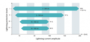
Figure 7: Lightning Protection Levels per IEC 62305-1 with Corresponding Minimum and Maximum Lightning Current Amplitude (redrawn from [16] with additional information).
4.4. Parameter of SPD
Common SPD specifications recognized by IEC 61643 are described below. They are used to select suitable SPD.
- Nominal Voltage, UN
It is the standard operating supply voltage of the apparatus or system circuit based on the use envisaged for the SPDs.
- Maximum Continuous Operating Voltage, UC
The maximum voltage that can be permanently applied to the SPD without damaging and triggering it. UC rating of the SPD is selected such that its triggering voltage is slightly higher than the nominal operating voltage (UN) of the equipment to be protected. This is to avoid SPD been accidentally triggered during normal operating.
- Voltage Protection Level, UP
Up is known as the “Let-Through” voltage or the clamped voltage in the industry. UP defines the maximum output voltage that could appear at the SPD terminal when tested with a specific waveform per IEC 61643. Generally, Up will be the maximum output terminal voltage of the SPD when subjected to transient surge. In practice, the SPD’s Up rating should be chosen so that its value is lower than the maximum SWC voltage of the apparatus to be protected.
- Nominal Load Current, IL
IL is defined as the maximum continuous RMS load current that is allowed to pass through the SPD without triggering and damaging the SPD, including the capability to withstand the current continuous thermal overload. This term is only applicable when the SPD is connected in series. Since a parallel connection is capable of handling an unlimited load current; hence, this term is not relevant to SPD connected in parallel.
- Impulse Current, Iimp
It is the peak current with 10/350μs waveform, direct strike, flowing through the SPD to test mainly for Type 1 SPD.
- Nominal Discharge Current, In
Peak current with 8/20μs waveform flowing through the SPD for the test of Type 2 SPD.
4.5. Implementation of SPD in the Ex Area
All guidelines highlighted in sections 4.1 to 4.4 are applicable when applying and installing SPD in hazardous areas. Additional factors described below to ensure the SPD does not become a source of the explosion also need to be considered.
4.5.1 Hazardous Area Classification
Classification of the hazardous area is a risk management tool that handles potentially flammable material to support explosion safety verification. Hazardous areas are defined by the occurrence of the type of hazards present, such as gas, vapor or dust; the probability of that hazard may be present; flammable concentrations on the lower explosion limits (LELs) and upper explosion limits of the explosive substance (UEL) as shown in Table 2. Hence, hazardous area classification is a systematic way to review, analyze and classify plant safety according to the explosive substance. This allows an optimum selection of the electrical apparatus or equipment installed in a hazardous atmosphere. ATEX and IEC standards classify the Ex area into Industry Group, Gas Group, Temperature Classification and Zone. The hazardous area’s electrical apparatus and equipment selection is based on the hazardous area classification defined by the ATEX / IEC standard.
Industry Groups:
- Group I is the mining industry, where equipment is used in the explosive environment that contains methane gases or vapors of its equivalent hazard, as shown in Table 3.
- Group II is the surface industry, as shown in Table 3. It is then further divided into three subgroups, that is Group IIA, Group IIB and Group IIC. Group IIA for the environment containing propane gases or vapors of its equivalent hazard; Group IIB for the environment containing ethylene gases or vapors of its equivalent hazard and Group IIC for the environment containing hydrogen gases or vapors of its equivalent hazard.
- Group III is also for the surface industry but with dust and fibers hazards. They are again subdivided into Group IIIA, IIIB and IIIC according to the nature of the explosive environment, as shown in Table 4.
Table 3 provides the information on Industry Group I and II; and the minimum ignition energy (MIE). MIE is the minimum energy required to ignite the easiest explosive gas-air mixture.
Table 2: Flammable Properties [17].
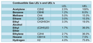
Table 3: Industry Group I and II for Mining and Surface Industry [17].
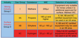
Table 4: Industry Group III for Surface Industry with Dust and Fibers Hazard [17].
![]()
Temperature Classification
Temperature Classification is also known as ignition temperature, auto-ignition temperature (AIT) or T class. It defines the device’s maximum surface temperature under a normal or abnormal condition with respect to the ambient temperature of 20°C to 40°C (unless otherwise stated) [18]. Depending on the types of explosion protection techniques used or its combination, for example, Exd, Exe or Exi, the temperature corresponds to the device’s external surface’s maximum temperature or the maximum temperature of the device’s internal surface (for example, Exi device putting into Exd junction box). For a combination of explosion protection techniques used (for example, Exdei – Exd, Exe and Exi are used in the device), the final temperature classification of the device needs to be determined. All flammable materials will have an AIT, the temperature at which ignition will occur without an external source. Apparatus must be selected with its temperature classification below the AIT. This will ensure the Ex environment’s apparatus is not exposed to the gas-air mixture with a temperature exceeding its AIT. If several different flammable materials are present within the same area, the material that gives the lowest AIT dictates the device’s overall applicable temperature class. The temperature classification only applicable to Industrial Group II (surface industry), as shown in Figure 8. Temperature classes do not apply to Group I (mining) applications. Mining equipment has either a rigid 150°C or 450°C limits [18]. Be noted that the device’s temperature class does not represent the operating temperature range of the device, but rather the maximum allowable surface temperature with respect to a default ambient temperature of 20°C to 40°C with the presence of flammable material.

Figure 8: Equipment temperature classification [19].
According to the ATEX directives, all the hazardous area installation apparatus, including SPD, must be marked with its temperature class and assigned an appropriate temperature classification according to the nature of hazard that might be present to maintain its integrity and prevent unexpected explosion due to AIT. For instant, if the hazard present is butane gas, its AIT is 372°C, then all apparatus used in that environment cannot generate a surface temperature exceeding 372°C. In this case, the apparatus rated T2 (300°C) to T6 (85˚C) will meet the requirement. This also means that for this case, all the apparatus used in the butane gas environment cannot have a surface temperature equal to or greater than 372˚C under fault or regular operation. Any equipment that generates 372˚C or more surface temperature could increase the possibility of an explosion.
Table 5: Zone Classification [20].
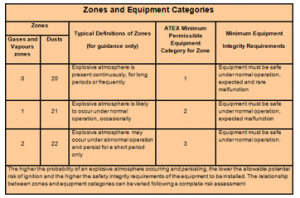
Zoning Classification
- Zone Classification: Classified concerning the probability of a potentially explosive environment being present in a 3-dimensional region or space and the duration for which it is likely to exist. The available explosion protection methods also depend a lot on the zone classification assessment and its assignment. The classification of the hazardous area is shown in Table 5.
- This rule of thumb derived fromAPI RP 505 and IP 15 stated if the hazard is continuously present for more than 1000 hours in a year is classified as Zone 0. If the hazard present between 10 to 1 000 hours in a year is classified as Zone 1. If the hazard presents less than 10 hours in a year is classified as Zone
Equipment Marking
- Equipment Marking: All certified apparatus used in the Ex area must carry mandatory marking. The standard uniformly defines the marking requirement. The marking on all equipment intended for use in a potentially explosive environment should provide all necessary and essential information for safe operation and easy identification at the site. Figure 9 and Figure 10 provide a self-explanation and sample of the manufacturer marking according to ATEX Directive 94/9/EC and the IECEx certification scheme,
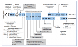
Figure 9: Summary of Apparatus Marking According to ATEX Directive 94/9/EC and IECEx Certification Scheme [21].
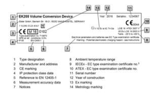
Figure 10: Typical Manufacturer Marking Tag [22].
5. SPD in Common Explosion Protection Technique
For an explosion to occur, three elements must be present at the same time, namely the hazard (flammable or explosive substance), supporter (air or oxygen) and the source of ignition (electrical spark or hot spot). All the explosion protection technique is to remove one or more of this element or contain the explosion so that it will not propagate to a bigger area or outside the enclosure. There are many explosion protection techniques used by the industry. However, only three common techniques and two practical examples based on Exi, intrinsic safety and Exd, flameproof explosion protection technique will be discussed here. Table 6 summarizes the various explosion protection techniques used in the industry, Ex code and its applicable zoning.
Table 6: The IEC Methods of Protection and Permitted Zone of use [23].

5.1. Intrinsic Safety, Exi
- Permitted to use in Zone 0, 1 and 2.
- Could carry out maintenance repair work without the need to turn off the power supply.
- The use of “Uncertified Simple Apparatus” is allowed when connected through a safety barrier.
- Typical Application with Exi protection is for instrumentation signal, control circuit and other low power apparatus like CCTV.
Exi is a low-energy signaling technique. It brings down the electrical energy level for the Ex area apparatus used below the ignition curve. In this concept, any electrical spark, thermal or hot spot effect in any part of the circuitry intended for use in Ex areas do not have sufficient energy to cause an explosion. Hence, the operation for live maintenance repair work can be carried out and is allowed. The energy levels available for signaling are small but useable and more than adequate for most instrumentation systems.
The minimum ignition energy is obtained experimentally using “SPARK TEST APPARATUS” [24]. The experiments have produced a general agreed “IGNITION CURVES”. These are the designer’s curves with suitable safety factors for safety parameters calculation (section 6.1 provides the detail on safety parameters calculation). Three curves are resulting from the experiments; they are Resistive, Capacitive and Inductive Ignition Curve, as shown in Figure 11 to 13, respectively.
The resistive ignition curve (Figure 11) provides the entity safety parameter on the maximum open-circuit voltage denotes as Voc and the maximum short circuit current denotes as Isc allowed to go into the hazardous area without causing an explosion for different Gas Group. Any combination of the voltage and current touching or above the curve could cause an explosion. A value below the curve will not have sufficient energy to cause an explosion. Equations (1) and (2) in section 6.1 provide the detail on the application.

Figure 11: Resistive Ignition Curve [24].
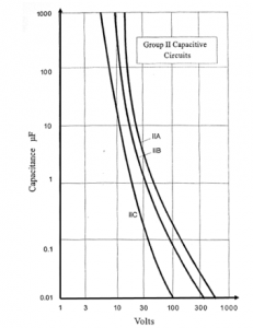
Figure 12: Capacitive Ignition Curve [24].
Capacitive ignition curve (Figure 12) provides the entity safety parameter on the maximum external capacitance (Ca) at the applied voltage allowed to be connected in the hazardous area for different Gas Groups. If the external capacitance (Ca) at the applied voltage is below the curve, it will not have sufficient energy to cause an explosion. Equation (3) in section 6.1 provides the detail on the application.
Inductive ignition curve (Figure 13) provides the entity safety parameter on the maximum external inductance (La) at the applied voltage allowed to be connected in the hazardous area for different Gas Groups. If the external inductance (La) at the applied voltage is below the curve, it will not have sufficient energy to cause an explosion. Equation (4) in section 6.1 provides the detail on the application.

Figure 13: Inductive Ignition Curve [24].
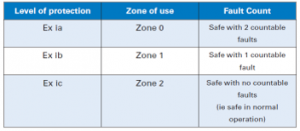
The IEC 60079-11 standard defines three categories of Exi protection. They are “Exia”, “Exib” and “Exic” with different fault tolerance levels, as summarized in Table 7. Only Exia category is permitted to apply in Zone 0.
With the introduction of intrinsically safe technique, the uses of “Uncertified Simple Apparatus” are allowed as defined by IEC 60079-25 in a hazardous area without additional certification when the simple apparatus is connected to the field through a certified safety barrier. IEC 60079-25 defines “Simple Apparatus” as an apparatus that does not generate or store energy more than 1,5V, 100mA and 25mW, such as mechanical switches and resistors, thermocouples and PT100. The simple apparatus also required to pass the insulation test at 500 Vrms (one-minute duration) to be used in the Ex area. The application of Simple Apparatus in the Ex area significantly brings down the cost of implementing intrinsically safe systems.
Table 7: Fault Tolerance on Exia, Exib and Exic [23].
5.2. Flameproof, Exd
- Permitted to use in Zone 1 and 2 only.
- The system needs to power down to carry out maintenance work. In other words, no live maintenance is allowed.
- Hot permit is required to carry out maintenance work.
- Wiring enters the Exd enclosure is via a flameproof cable gland or flameproof barrier.
- Typical applications will be rotating machines, lighting, switches (start/stop button) and junction boxes.
The flameproof protection technique relies on housing design to ensure an explosion or ignition inside the enclosure will not propagate outside the enclosure. It is achieved using different flame path designs. There are three possible flame path designs, as shown in Figure 14. The flame path construction plays a significant role. It creates a longer flame traveling distance so that the hazard gas generated during the internal explosion has sufficient time to cool down below the permitted AIT. The enclosure design also must be capable of withstanding the explosion’s pressure and, at the same time, preventing the hazard gas from entering the enclosure and contact with the protected equipment inside the enclosure.

Figure 14: Types of Joint
The Exd enclosure usually is supplied in a complete assembly. The manufacturer or its approved agent does all the internal components assembly and wiring work. Both the manufacturer and the approved agent must have a certified facility and trained person to carry out the work. An approved test authority certifies the assembled system as a single entity as system approval (see section 6). Only a single system certificate will be issued. The test procedure for the approval include:
- Ventilation – Consider the available free air volume to ensure sufficient air circulation and ventilation after all the electrical components are fitted and wired.
- Temperature Classification – Consideration of the temperature rises to comply with the temperature classification and define the temperature class;
- Creepage and Clearance: Check all creepage and clearance distance requirements (see Figure 15 on the difference between creepage and clearance distance).
- Pressure Piling – Consideration of the rise in air pressure resulting from the internal enclosure explosion by considering the worst-case scenario on the gas-air mixture.
Future component replacement during maintenance should use back the initially designed component specification. If the replaced component has a larger or smaller dimension than the initially installed part, it will affect the enclosure’s internal geometry and ventilation. When a larger than the original component is replaced, pressure piling could happen. If a smaller sized component is replaced, more free air volume will be generated. Meanwhile, the heat conductivity and heat dissipation characteristics of an object are affected by the geometry, ventilation and the material used. This will significantly affect the temperature classification rating. The initial temperature rating of the enclosure could be void.
Drilling and tapping the hole on the enclosure for fitting the cable gland, breather and conduit by a third-party technician is strictly prohibited or else the certification is considered void. The installation of these auxiliary components can only be carried out by the enclosure’s manufacturer or certified installer. The type of threads, thread pitch and the clearance tolerance for a particular junction box must be compatible with the cable glands, breather or conduit as flame paths exist at these points.
To improve the ingress protection (IP rating), for example, for weatherproofing applications, non-hardening grease material or non-setting grease or compounds could be applied to the joint. Installation of gaskets to increase the ingress protection is not allowed if they are not part of the original design. It will affect the internal enclosure pressure release efficiency during the explosion. The gasket can only be replaced. Consult the manufacturer and check the installation manual on the type of gasket that could be used.
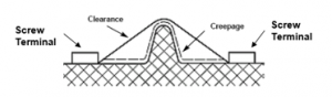
Figure 15: Different between Creepage and Clearance Distance
5.3. Increased Safety, Exe
- Permitted to use in Zone 1 and 2 only.
- Required to turn off the power before carrying out maintenance work. In other words, live maintenance is not allowed.
- Minimum IP rating is
- No hot surface.
- Good mechanical strength (detail refer to EN50014).
- Typical applications will be in lighting, junction boxes and terminal blocks.
Increased Safety, Exe is an explosion protection technique applied to the hazardous area installation that ensures no hot spot or no excessive temperatures and no sparking occurrence from hazardous area electrical equipment and accessories. Equipment and the design that normally cause sparks are excluded from use within this method of explosion protection.
Exe relies on housing construction to withstand mechanical impact with a minimum of IP54 rating. The design of Exe ensures that under any operating mode, the apparatus does not contain normally arcing, sparking devices or hot surfaces that could cause ignition. This protection is realized by using high integrity insulation material. The designer also needs to consider the temperature de-rating factor of the insulation materials and enhanced terminal creepage and clearance distance (made wider than is generally the case in the general industry). The terminal design must be generously dimensioned for the intended cable connection and ensure that conductors are securely fastened to prevent arcing (loose connection can cause arcing). When designing the Exe protection method, a possible spark created by friction should be taken into consideration as well.
6. Method to Protect Assets in Hazardous Area
As shown in Figure 16, the mounting locations of the SPDs in a typical hazardous process plant.
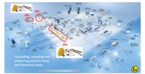
Figure 16: Typical Hazardous Process Plant with SPD (redrawn from [25] with additional information)
6.1. Application Example on SPD in Exi Control Loop
- Permitted to use in Zone 0, 1 and 2.
- Maintenance work could be carried out with the power on. In other words, live maintenance is allowed
- No further certification is required when using “Uncertified Simple Apparatus” in combination with a certified safety barrier
There are two concepts of Exi applicable to intrinsically safe systems. They are “System Approval” and “Entity Concept”. The meaning of system approval indicates that a single certificate is issued by the approving authority such as BASEEFA or TUV, including the SPD, safety barrier and the field device, as shown in Figure 17 as the components inside the dotted line box. Uncertified control equipment, for example, DCS, PLC or ESD are installing before the safety barrier in the control room; they are not included in the system certificate. In fact, they do not require certification because the energy transmitted to the hazardous area in the field is already clamped down by the safety barrier when there is any fault that happened. Although there is no certification requirement for the uncertified control equipment, they are governed by the installation code, such as the requirement on cable segregation for Ex and Non-Ex cable; creepage and clearance distance for the terminal block; color code and so on. System certificate can only be issued after comprehensive testing and assessment by both the approval authority and the equipment manufacturer. Installation guidelines must be followed strictly according to the certificate/manual’s instruction and wiring diagram provided. In the case where the fault happened, all replacement parts will have to be replaced with the exact original model used else; the certification will no longer be valid. This is not so flexible and, in some cases, will post difficulty when any of the parts are obsolete. When the exact replacement part is not available, then replacement on an entirely new set of the system will be required; otherwise, the newly installed component needs to be re-certified.

Figure 17: System Approval (redrawn from [1] with additional information).
The most significant advantage of a system certification is to ensure that it is a proven and tested system. The approving authority and equipment manufacturer will be fully responsible for explosion protection in terms of safety. However, this led to the absence of flexibility in changing the component when it is discontinued. The responsibility of the installer is to follow strictly the installation instruction provided by the certificate. As for the entity concept, all intrinsically safe loop components, as shown in Figure 17 as the dotted line box, need to be individually tested and certified to use in Ex area. A separate certificate will be issued individually with all the safety parameters and other special clauses if any. It is the responsibility of the user to match the safety parameter, which will be described later. The utilization of the entity concept provides more flexibility in terms of parts selection, repair and equipment replacement. Regardless of the manufacturer, any product could be used from the safety perspective as long as the safety parameters are satisfied. However, in practice, the device can only be used if they fulfilled both safety and operational parameters. The operational requirement, such as it must have enough voltage and current to drive the field device.
Safety Parameter on Entity Concept
The entity safety parameters are described below:
![]()
Where Vmax is the maximum voltage specified by the field device manufacturer (tested by approval authority) that could be applied safely to the terminal of an intrinsically safe field device, Voc denotes the maximum open-circuit voltage (tested by approval authority) that could appear at the safety barrier’s output terminal when the fault occurs.
![]()
Imax is the maximum input current specified by the field device manufacturer (tested by approval authority) that could be applied safely to the terminal of an intrinsically safe field device. Isc denotes the maximum output short-circuit current (tested by approval authority) that could be generated from the safety barrier’s output terminal when a fault occurs.
![]()
Ci is the intrinsically safe field device’s internal unprotected capacitance (tested by approval authority). Ccable denotes the cable capacitance.
Ca is the maximum external capacitance (individually tested by approval authority), including all devices at the field that could be connected safely to the hazardous terminal of the safety barrier.
![]()
Li is the intrinsically safe field device’s internal unprotected inductance (tested by approval authority). Lcable denotes the cable inductance.
La is the maximum external inductance (individually tested by approval authority), including all devices at the field that could be safely connected to the terminal of a safety barrier.
The value for Vmax, Voc, Imax, Isc, Ci, Ca, Li and La could be obtained from the individual intrinsically safe certificate issued by the approval authority. It is usually supplied together with the product, where Ccable and Lcable can be obtained from the cable manufacturer’s datasheet.
Only the system that fulfills all four mentioned equations, i.e., equations (1), (2), (3) and (4) could be used and safely installed according to the entity concept. However, the user also must take into consideration the operational requirements; for example, it should have sufficient voltage and current to drive the field equipment. Only systems that fulfill both operational and safety requirements will be implemented.
Entity parameters may be found on the control drawing supplied by the equipment manufacturer, along with other pertinent information regarding proper connections, conditions of use, etc. Figure 18 is an example of a control drawing for Exi equipment assessed based on the entity concept.
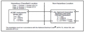
Figure 18: Example of Control drawing for Exi apparatus assessed based on the entity concept [26].
When an SPD is mounted in the safe area where no hazard substance is present, for example, in the control room, temperature classification and the type of hazard classification such as hazardous gas are not applicable; therefore, it will not be considered here. However, for field mounted SPD where hazard substance is present (Ex area); temperature classification and hazard classification need to be considered.
Figure 19 shows two SPDs connected in series, while Figure 20 shows one of the SPD, field mounted SPD connected in parallel and the other SPD (mounted in a safe area) is connected in series. For the case where all SPDs are mounted in the safe area, then there is no specific requirement for temperature and hazardous area classification. However, temperature and hazardous area classification must be taken into consideration if SPDs are to be mounted in a hazardous area. The hazardous area classification information of the individual Ex rated device can be found in the certifying authority’s intrinsically safe certificate. Since all the SPDs in Figure 19 and Figure 20 are part of the Intrinsically Safe loop; therefore, it is a mandatory requirement to perform the entity safety parameter checking (equation (1) to (4)) to ensure its operational safety.

Figure 19: Entity parameter matching for SPD connected in series at the field [27].
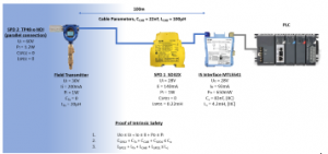
Figure 20: Entity parameter matching for SPD connected in parallel at the field [27].
6.2. Application Example on SPD in Exd Control Loop
- Permitted to use in zone 1 and 2 only.
- Need to turn off the power before maintenance work is carried out. In other words, no live maintenance is allowed.
- Hot permit is required to perform any maintenance job.
SPD used in the Ex area is required to mount inside the Exd enclosure. The following information is required to determine the suitable size of Exd enclosure:
- To determine the enclosure’s overall size, all the dimension on the individual component to be mounted inside the Exd enclosure is necessary. The system design for heat dissipation and ventilation on top of component size needs to put into the calculation as well.
- Temperature profile or T classification, heat or power dissipation information for the individual component is needed to identify the overall temperature classification of the Exd enclosure. In this case, if the temperature, heat or power dissipation information is not available, the system will need to perform temperature profiling to determine the maximum surface temperature by powered on for an extended period of time using a temperature probe. A bigger system may be required to power on for multiple hours until the temperature rise reaches a stable point where the measured temperature achieves equilibrium, stable and saturated.
- The manufacturer needs to know the type of hazard that could be present, for example, propane, ethylene or others, to determine the kind of joints and its design, either flanged joint, threaded joint or spigot joint. However, in most cases, it is the other way around; the manufacturer states their design is suitable for what kind of hazard. The user’s choice is based on the hazard present in their application.
- Hazardous area mounting location or zoning: This is to determine the appropriate type of explosion protection technique. The flameproof (Exd) protection method can only be permitted to apply to Zone 1 or Zone 2 only.

Figure 21: Obstruction of Flame Path (redrawn from [1] with additional information
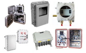
Figure 22: Sample of the Exd Enclosure
During installation, it is crucial to ensure that there is no blockage such as a wall, brackets, conduit, weather guards or other electrical equipment near the opening of the flame path joint, as shown in Figure 21. The presence of such obstruction could reduce the efficiency of the flame path in the event of an internal explosion. Therefore, the minimum distance requirement between the flame path opening and the obstruction must be satisfied. Figure 21 provides the minimum distance requirement as recommended by IEC 60079‐14.
Sample of the Exd enclosures fitted with various Ex and Non-Ex components are shown in Figure 22. It is also a common industrial practice that all the internal assembly and wiring work inside the Exd junction box is carried by the manufacturer or a certified center or an approved agent to ensure compliance.
7. Summary
When selecting SPD for hazardous area application, two criteria involve:
- Equipment protection
The parameters to be considered to protect the equipment from surge:
- Types of SPD: SPD installation location correspondence to discharge surge energy. This is different from hazardous area classification. It is applied to the installation location for both Ex and non-Ex area.
- LPZ and LPL to determine the kA rating of the SPD.
- Let-through voltage (Voltage Protection Level, UP): SPD should be selected where the let-through voltage is below the SWC of the device to be protected.
- Bandwidth: only require when it is used for the communication line.
- Maximum continuous operating voltage, UC: The UC rating of the SPD should be selected slightly higher than the UN (nominal operating voltage) of the equipment to be protected so that during normal operation, the SPD is transparent to the system.
- Nominal load current, IL: For a series connection, the load current needs to be determined so that the SPD’s current passing will not damage the SPD. The SPD must be able to withstand the continuous thermal current load. This only applies when the SPD is connected in series whereas SPD connected in parallel is able to handle unlimited load current.
- Series voltage drop: This mainly applicable for signal SPD where a series connection is applied. After adding the SPD, the user needs to ensure the voltage drop does not affect the circuit operation.
- Explosion protection
These are the factors that are nothing to do with the equipment protection from surge but rather to ensure the SPD itself does not become the source of ignition.
- Industry Group: provides information on the type of industry (example: mining or surface industry) and the type hazard substance such as vapor, gas or dust that may be present, and its minimum ignition energy.
- Temperature Classification: provides information on the maximum surface temperature of the equipment at fault condition. The temperature classification of the equipment mounted in the Ex area should fall below AIT of the hazardous substances present. For the process loop application, only the SPD mounted at the field will have the temperature classification (Ex are). The other SPD mounted in the control room (non-Ex area) will not have the temperature classification.
- Zoning Classification provides information on the probability of a particular hazardous substance being present. The applicable type of explosion protection method depends on the Zoning information and the type of hazard present.
- Two approval concepts for safety evaluation could be adopted, entity or system approval. Entity Approval is a technique to combine individually approved apparatus into an intrinsically safe circuit. Two apparatus from different manufacture could be interconnected together as long as it could fulfill the safety calculation spell out by equation (1), (2), (3) and (4), no need for the two apparatus being tested in combination. System Approval is a technique to verify the intrinsic safety of a circuit in which all of the interconnected devices are examined all together as a complete system.
Conflict of Interest
No conflict of interest.
- T.H. Kuan, K.W. Chew, K.H. Chua, “Practical approach on surge protection device for Ex application,” in 2019 IEEE International Conference on Electrical, Control and Instrumentation Engineering, ICECIE 2019 – Proceedings, 2019, doi:10.1109/ICECIE47765.2019.8974781.
- J. Kain, Severe Weather 101: Lightning FAQ, NOAA National Severe Storms Laboratory, Nov. 2020.
- MTL, Lightning surge protection for electronic equipment-a practical guide, Rev G, Measurement Tecnology Limited, Luton, 2016.
- M. Ahrens, LIGHTNING FIRES AND LIGHTNING STRIKES, National Fire Protection Association Fire Analysis and Research Division LIGHTNING FIRES AND LIGHTNING STRIKES, Quincy, 2013.
- A. Davis, Surge protector sparks fires instead of preventing them, homeowners say, Click2Houston.Com, 2015.
- K.F. Company, Kimberton Fire Company – Chester County, PA, Firehouse Solutions, 2020.
- P.ˇ Stroch, “ScienceDirect Do not underestimate danger of explosion; Even dust can destroy equipment and kill,” Perspectives in Science, 7, 312–316, 2016, doi:10.1016/j.pisc.2015.11.048.
- MTL, Working Principle of Surge Protection Device, Luton, 2019.
- F. Martzloff, Surge Withstand Capability of Various Devices, Schenectady NY, 2019.
- F. Kloer, G. McDonald, N. Desai, TRICON v10 Nuclear Qualification Project: SURGE WITHSTAND TEST REPORT, Boxborough, Massachusetts, 2008.
- I.A. Metwally, A. Gastli, M. Al-Sheikh, “Withstand capability tests of transient voltage surge suppressors,” Electric Power Systems Research, 77, 859–864, 2007, doi:10.1016/j.epsr.2006.07.011.
- PHOENIX CONTACT | Information on NFPA 79, 2018 Editi, PHOENIX CONTACT GmbH & Co. KG, Blomberg, Germany, 2018.
- Guide to Surge Protection Devices ( SPDs ): selection , application and theory, BEAMA Ltd, London, 2018.
- IEC, INTERNATIONAL STANDARD Protection against lightning-Part 4: Electrical and electronic systems within structures, 2.0, INTERNATIONAL ELECTROTECHNICAL COMMISSION, 2010.
- N. Sclater, J.E. Traister, Surge protective categories defined by ANSI/IEEE C62.41, Electrical Engineering Portal, Nov. 2020.
- The basics of surge protection, PHOENIX CONTACT GmbH & Co. KG, Blomberg, Germany, 2016.
- C.P. Yelland, M.I. Lythe, Selection of explosion protected equipment for hazardous locations, EE Publishers, 2016.
- Temperature Classification (T class) – what it means, Control and Instrumentation.Com, Nov. 2020.
- IS MY TORCH CORRECTLY CERTIFIED BY ATEX?,” LEARN ALL ABOUT ATEX DIRECTIVE 2014/34/EU, 2017, Peli Products Germany, Nov. 2020.
- I. Harrison, “HAZARDOUS AREA CLASSIFICATION,” When is hazardous area classification needed?, Ex-Consulting, Nov. 2020.
- G. T., Understanding Hazardous Area Classification, Instrumentation Tools, Nov. 2020.
- Elster, Operating manual Volume conversion device EK205, Mainz-Kastel, Germany, 2016.
- P. Saward, Ex ic Intrinsic safety’s new protection level, Luton, UK, 2016.
- T.H. Kuan, “INTRISIC SAFETY MADE EASY Title: INTRINSIC SAFETY MADE EASY,” in Instrumentation & Control Society, ICS, Kuala Lumpur, 2006.
- MTL, Controlling, operating and protecting assets in harsh and hazardous areas MTL scope of supply, Measurement Technology Ltd, Luton, UK, 2017.
- T. Report, Intrinsically Safe System Assessment Using the Entity Concept, North Carolina, 1995.
- MTL, “Entity Concept Calculation,” MTL Training Slide, Luton, UK, 2020.