Ultra Wide Band-based Control of Emulated Autonomous Vehicles for Collision Avoidance in a Four-Way Intersection

Adv. Sci. Technol. Eng. Syst. J. 5(6), 724–730 (2020);
 DOI: 10.25046/aj050687
Traditional crossroads use traffic lights, but may cause delays due to its stop and wait process. Moreover, autonomous vehicles are being made, although it is not yet mass-produced. This work presents a design and implementation of an agile system that communicates and coordinates autonomous vehicles entering the intersection by adjusting their speeds and maneuvers to avoid collisions, allowing them to weave and pass through intersection traffic and avoiding them to completely stop, leading to an increase in the throughput of the intersection, and therefore reducing congestion. A centralized computer implements agile communication and controls the system based on a first-come-first-served policy. The hardware implementation emulates four prototype vehicles modeled as radio-controlled cars integrated with an ultra wide band (UWB) localization technology. The cars were used to simulate the passage without collision in a typical four-way intersection. Pozyx UWB modules were chosen for tracking the vehicles due to its compatibility with Arduino as well as its numerous other functionalities and accuracy relative to other indoor-positioning systems. Results show that Pozyx could track autonomous vehicles. The study resulted in a system that can control self-driving cars through the intersection with key measures. Moreover, the characterization of Pozyx in this hardware implementation was observed.
1. Introduction
Traffic problems have risen with the increase in vehicles, users, roads, and crossroads. Numerous traffic delays and accidents occur in various locations, and one of the most concerning of these is crossroads. Smith [1] said that almost forty percent (40%) of all crashes in the United States involves crossroads, and about 165,000 accidents occur annually in crossroads caused by red-light runners. Crossroads are designed to lessen accidents, traffic congestion, and increase efficiency, but these become a source of problems. Erring drivers, vague navigation signs, and blind curves are some of the reasons for these. Although the installation of stoplights and various signs at crossroads are seen as solutions to these problems, these devices have not been as effective. These devices are not so good for traffic calming, and this meant that these may make the flow of vehicles better but not necessarily safer for drivers [2]. Accidents increased when traffic signals were introduced, and these devices are not the solutions to less dangerous roads [3]. Proposals to solve these problems include the introduction of autonomous vehicles (AV) and intelligent intersection management, but there have been very few implementations in actual situations. Communication between AVs and road infrastructure is also important to ensure road safety [4]. Moreover, AVs can be enhanced to intelligent vehicles by adding high technology features like efficient 3D road map exchange in real-time for navigation and localization [5]. The study plans to address the problems of accidents and traffic congestion at crossroads using prototype AVs with attached Pozyx whose speeds and turns are controlled by a centralized control communications system. Pozyx [6]–[10] modules are ultra-wide band-based devices for localization. In this paper, vehicles are referred to as autonomous, which is also known as self-driving cars. The use of Pozyx was also characterized in terms of accuracy and delay for tracking and localization of AVs.
In crossroads, vehicles must coordinate their movements to pass through without collisions. In an ideal situation, vehicles would only have to accurately adjust their speed and direction to create a sufficient duration for the intersecting vehicle to weave through without stopping. Furthermore, the vehicles should be able to process and execute these maneuvers with high precision and minimal delay to avoid collisions. Unfortunately, the current system in crossroads is traffic light-based where vehicles have to stop and wait for intersecting vehicles to pass. Vehicles are needed to stay idle when their road is asked to stop, interrupting their journey. At present, almost all vehicles are operated by humans, but in the future, the proliferation of AVs can be seen, and this is the context of this study. The focus of this paper is on the use of Pozyx for communication and localization of autonomous vehicles through a central computer system so that they can pass in crossroads without collision.
This research on autonomous intersection management helps address traffic-related problems and congestion at crossroads. The modified and programmed autonomous vehicles would be able to adjust their speeds at crossroads without stoplights resulting in a more efficient flow of traffic and a decrease in traffic congestion and accidents. The software algorithm in the centralized system determines the speed of each car passing the crossroad and calculates the appropriate angle of turn for each of these vehicles so that collisions would be avoided. The centralized system communicates with each of the vehicles to allow the flow of traffic at crossroads to be orderly and continuous, and thus, would save time. With the increase in research about autonomous and intelligent vehicles, this study is an add-on with its contributions such as agile control software for collision avoidance of AVs using a first-come-first-served (FCFS) tile-based approach with graphical user interface (GUI), and its hardware adaptation of collision avoidance in small-scaled miniature AVs with attached Pozyx for tracking and localization.
It is assumed that connection quality between the vehicles and the central computer is ideal in this study. The crossroad is also assumed to be initially free of obstacles such as foreign objects and road hazards. Four scaled-down controllable vehicles running simultaneously in a four-way two-lane crossroad utilizing a clover-shaped track free of obstacles were included in the scope of the hardware implementation. Moreover, the scope of the study includes a control system that monitors the velocity of the vehicles and performance measures of the system through its vehicle throughput. The study is delimited by the following: human-driven vehicles are not factored in, the vehicles do not abide by the SAE Level 5 definition of driving automation [11], and the cars cannot recognize foreign obstacles which are any object that is either not an element of the track or another object not running as part of the system.
The system has two main parts: the software algorithm and hardware control system. Its overview is illustrated through a block diagram shown in Figure 1. The system is described as agile since it is meant to quickly react and adapt to vehicles entering the crossroad and managing it according to the other vehicles. Moreover, it is then described to be collision restrained as it would avoid letting cars collide in the crossroad. This means that if there are multiple vehicles with current trajectories expected to collide, the algorithm adjusts their velocities to avoid this potential outcome. The software runs the crossroad algorithm and the communications interface. The control communications system deals with the controllers of the scaled-down motorized cars which are referred to as ‘vehicles.’ The microcontrollers would have their own wireless communications module that uses either Bluetooth or Wi-Fi. Moreover, the tracking and location features were added through Pozyx. This control communications system is responsible for taking in data from the different sensors of the vehicle and relaying the information to the agile control communications. They also control the motors for the instructions sent back. The actual hardware of the project is focused on the vehicles and their sensors.
The system is tested to measure its vehicle throughput. In each trial, the authors adjusted the number of vehicles active and running on the track to change the load on the crossroad. Varying the load on the crossroad would account for real-life situations such as rush hours. The recorded delay is the time it takes from sending a reservation request to exiting the crossroad. They then adjusted the average speed of the cars and then further recording the delay of the cars, as well as the chances of collisions. Using the data gathered from the trials, linear scaling was performed to see how the data would project to real-world cars and crossroads.
This paper is organized then as follows. Section 2 gives further details of the design of the overall system, and its corresponding components. Section 3 provides the results of the design, and lastly, Section 4 concludes the paper with recommendations for future work.
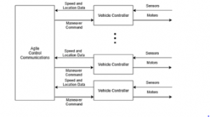
Figure 1: Block diagram of the control system.
2. System Design and Methodology
2.1. Pozyx
Pozyx is a UWB-based real-time location system utilizing both hardware and software to be able to provide accurate positioning information with an advertised accuracy of up to ten (10) centimeters compared to other traditional indoor location tracking systems, such as Wi-Fi or Bluetooth which are accurate within several meters [6]–[9], [12]. This localization is achieved through the use of UWB technology combined with smart filters as well as machine learning, thus, allowing positioning to be done even in indoor environments without a clear line of sight to the reference points. To obtain precise and accurate positioning, two-way ranging is done between the Pozyx tag and at least three reference points, or Pozyx anchors, followed by trilateration. These anchors are ideally spread out as much as possible and placed at the corners of the space in which location tracking will be performed to get the most reliable data. The anchor may be reprogrammed to work as a tag as well and does not need an Arduino to function as it is designed to operate on its own.
The Pozyx tag is an Arduino compatible shield which makes use of Pozyx anchors to provide accurate positioning as well as other types of data such as its orientation using its 9-axis inertial measurement unit. It is also equipped with different sensors along with a UWB transceiver based on the DW1000 UWB-chip from Decawave which, in addition to performing ranging, can also be used for wireless messaging. Figure 2 displays the pinout of a Pozyx tag, whereas Figure 3 for the anchor. Pozyz interfaces with Arduino through I2C communication. It can also interface with Raspberry Pi through a micro-Universal Serial Bus (micro-USB).
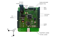
Figure 2: Pozyx Tag Pinout [6]
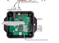
Figure 3: Pozyx Anchor Pinout [6]
For this study, Pozyx was chosen to be the basis for tracking the RC Cars due to its compatibility with Arduino as well as its numerous other functionalities and accuracy relative to other indoor-positioning systems. In addition to being easy to set up for most indoor environments, it also provides different possible configurations to optimize its performance to meet the desired need whether it be accuracy or speed. Figure 4 provides visualization on how the location of a Pozyx tag is obtained about the anchors as well as to the Master Pozyx tag. It may be seen that each Pozyx tag does not automatically provide its location as it only does so when it is asked first. Once asked, it will then calculate its location using the four Pozyx anchors as a reference at which point, the tag then finally sends its position data back to the Pozyx master.
2.2. Arduino Uno
The Arduino Uno acts as the brain of the RC car as it processes commands received through Bluetooth as well as utilizes the connected Pozyx tag to perform the necessary maneuvers to ensure that it follows its intended path.
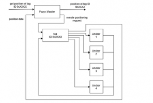
Figure 4: Pozyx Block Diagram
2.3. Radio-Controlled Car
A Radio-Controlled (RC) car is a battery-powered model car which can be controlled by remote control, mostly done through radio, hence, the term ”radio-controlled”. These RC cars represent a scaled-down model of real cars. A typical RC car has a receiver that captures radio signals from its remote control. To simulate the algorithm and adapt it into hardware, RC cars are used. In this research, the cars were modified by adding different modules to their parts. A location module is added to track the car’s position, and the RC communication is replaced with a sophisticated communication module. A microcontroller is added to manage the modules and control the car. The movement of the RC car is driven by motors. A motor driver is used to interface the microcontroller and the motors providing motion to the RC car. The motor driver in the system is powered using a power bank separate from the microcontroller circuit. The motor driver chosen for RC cars was the 2-Channel Tiny DC Motor Driver from e-Gizmo based on Allegro’s A3906 low voltage dual DC motor driver IC.
2.4. FCFS Software
The tile-based first-come-first-served (FCFS) policy, developed by Dresner and Stone [13], is the basic reservation system. ACC applies the FCFS approach for the reservations of vehicles, meaning that vehicles that requested a reservation will be entertained first. When another vehicle requests for a reservation, it will be checked first from vehicles that had made successful reservations earlier. A centralized computer provides coordination by communicating with AVs and managing their reservations. When a vehicle sends a request, the ACC simulates as if the vehicle will pass through the intersection. The reservation is tile-based, in which collisions are detected if a vehicle occupies a tile reserved by another vehicle. If at least two vehicles occupy the same tile, which would result in a collision, the request is rejected. Otherwise, it is accepted. The significance of adopting the FCFS is its versatility because it can be extended to be used in many different purposes in autonomous intersection management.
2.5. Car Simulation
The car runs on a program independent of the ACC. For reservations to commence, the car software and the ACC, which employs the FCFS algorithm, must exchange information. The ACC follows the principle of Autonomous Intersection Management [14]. The simulation of the cars would maintain minimal communication complexity. After the reservation, it is the responsibility of the car to meet the reservation at the correct time and place.
2.6. Pozyx in RC Car
In modifying the RC car, an Arduino was added. The Arduino was interfaced to a Bluetooth Module through Universal Synchronous-Asynchronous Receiver-Transmitter (USART), and two motor drivers that power the motors. Two 5 V, 3600 mAh power banks, energize the Arduino and the motors. Moreover, a Pozyx tag is attached to the Arduino, which communicates with it through I2C. It does the job of accurately locating and tracking the cars through UWB. The Pozyx localization system employs four reference anchor modules, with one of the anchors interfaced with an Arduino that is connected via a serial interface to a computer that runs the simulation software. The Pozyx tag relays the location of the car where it was attached. It also orients the car at an angle from 0◦ to 360◦. The Bluetooth BLE HM-10 module receives commands which the Arduino module then decodes. The decoded instructions determine which of the two motor drivers activates the corresponding motor driver depending on the received instruction. The two motor drivers present in each RC car are responsible for controlling both its steering and acceleration depending on the instruction decoded by the Arduino with one motor driver handling the steering motor and the other handling the throttle motor. The components are interconnected as shown in the block and circuit diagrams of the RC car illustrated in Figure 5 and 6.

Figure 5: RC Car Block Diagram
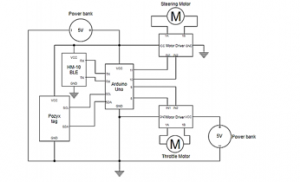
Figure 6: RC Car Circuit Diagram
2.7. Communication Protocol
The communication protocol is the medium at which the software running on the computer can interface with the Pozyx modules as well as issuing commands to the AVs. The study has opted to make a standard protocol that handles the execution of functions as well as sending data to and from the central computer software and the hardware controllers. Although there are several uses for the protocol their format is similar regardless of whether they are between the data collection of the Pozyx or the command issuing for the cars. Between the computer program and the connected microcontrollers that handle Pozyx and Car communication, the format of their messages are as follows: preamble, length, message type, and data. The preamble is a predetermined set of bytes used to indicate to the receiver that a message is incoming. Next is the length byte. It is a single byte used to indicate the length of the entire message. This can vary depending on the number of bytes used for sending data if applicable. Additional details can be found at [6].
2.8. Scaling Method
The method used to establish the scaling between the RC car and an actual vehicle is based on the turning radius of the RC car instead of its dimensions. This is because it was observed that its steering angle is much larger than that of life-sized cars which resulted in the RC car taking wider turns than what was expected based on its dimensions. As a result, the dimensions of the test track are based on the turning radius of the RC cars, the resulting dimensions of the car, as well as its speed in simulation, would be proportional to the ratio between its turning radius and the average turning radius of most common midsized passenger cars today of 17 feet or 5.18 meters [15]. After the computation based on Equation 1, a scale factor of 15.94 was obtained. The scaling process is illustrated in the block diagram in Figure 7.
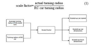
Figure 7: Scaling Process Block Diagram
2.9. Materials
The materials used are summarized in Table 1.
Table 1: Materials
|
2.10. System Block Diagram
- The entire system block diagram is shown in Figure 8. The inputs of the system are user interface (UI) inputs, track dimensions, and car initial states. The center shows the various processes that run in the software which process all the data from the inputs and produce the corresponding outputs. The main outputs which correspond to the key measures of the project are UI output, car motion, number of collisions, and duration in the crossroad.
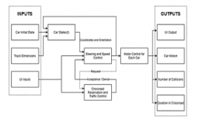
Figure 8: System Block Diagram
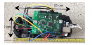
Figure 9: Dimensions of Scaled-Down Model Car
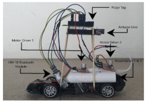
Figure 10: Scaled-Down Model Car Side View
3. Results, Analysis, and Discussions
3.1. Prototype Car
The resulting scaled-down model as shown in Figure 9 is twenty (20) cm in length and five cm wide, as it small enough to not require a large test track while big enough to mount all the components needed. The car was able to fit all the components in its shell but would likely negatively impact the Pozyx tag’s connection to the nearby anchors due to the shell preventing a good line of sight. Discovering that Pozyx had more accurate results if it was elevated higher from the ground, long thin sticks were used to prop it up. The car goes through different types of movements and vibrations during testing, and thus, the components and their connections to each other must be secured. Therefore, connecting wires to motor drivers must be directly soldered, as seen in Figure 10. The motor drivers and power banks were also attached. The resulting characteristics of the four prototype cars are shown in Table 2. With the same throttle level, the four cars have different speeds. This variation in average speeds is less than ideal when compared to the perfect scenario of having all four cars perform the same at each throttle level. It was also observed that the measured average car speeds on later trials were generally slower compared to the earlier trials. This indicated that their speeds decrease as they are used due to the car’s power banks being discharged.
|
Table 2: Car Speed Characteristics
|
||||||||||||||||||||||||||||||||||
The four prototype cars running simultaneously in their physical track with specified dimensions are shown in Figure 11.

Figure 11: Test track
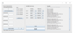
Figure 12: Graphical User Interface
3.2. User Interface for the Control
The graphical user interface (GUI) of the system provides the users with an easy way to set up and initialize the hardware and setting up the parameters for each test case. The latter function specifically assigns the initial locations of the car as well as injects them with the turn maneuvers that they will execute later during run time. As shown in Figure 12, the GUI window is divided into three sections, Pozyx Communication, Test Case, and results.
3.3. Control Capability Results with Pozyx
Pozyx is used to locate and track cars in real-time. It gives position and orientation to the system which helps it determine the speed and steering required by each car in the track. One of the most important functionalities of the Pozyx is providing the software program with real-time accurate position and orientation for the program that determines the speed and steering for each car in the track. However, the Pozyx updates are too slow in comparison to the speed of the cars reducing the accuracy of tracking the cars as they cross the intersection. The issues encountered with the Pozyx are about location accuracy and delay in updates. The company that sold the Pozyx modules listed a location accuracy of 5 to 10 centimeters while the update rate for each tag was 16 milliseconds. However, the data obtained in the study did not match these characteristics, leading to numerous problems in the performance of the system and the run of each car in the track. The authors performed tests using one Pozyx tag at a time followed by multiple tags to determine the accuracy of Pozyx and the consistency of its performance. The important factors that were observed were the accuracy and delay in the results provided by Pozyx. For each test, the Pozyx tags were placed in a location within the Pozyx anchors. The location provided by Pozyx was compared to the actual location to evaluate the accuracy of Pozyx. Fifteen tests were performed for one Pozyx tag at a time, while one test was performed that used four Pozyx tags simultaneously. The authors were able to note some issues regarding the Pozyx accuracy by testing the Pozyx tags. In the tests done for one tag at a time, the error for accuracy showed a range of 10 to 40 cm, and there were some cases where the delay reached more than a second between updates. There were also cases when no data location was shown for an update, and some of the location data freeze between updates. It was observed that there was a different location for the tags in each test. These location points were chosen based on critical points that tested the functionality of Pozyx in terms of accuracy in data location. Moreover, the test was done on four tags and the delay was more than 0.2 seconds and the error is from 20 to 50 cm for some tags. The graphs of the differences and deviations are shown in Figure 13 and Figure 14, respectively. In the system, accuracy and delay are very important factors in determining the speed and steering for each car. Hence, when the system receives location data that is not accurate, there will be many problems in the performance of the system and movement of the cars. In addition to receiving larger location inaccuracies than was expected, there were also numerous instances of outputting negative location values implying that the tag being located was out of bounds when it was not in reality. This can be seen in Figure 15 wherein Pozyx outputs Y coordinates that are nearly half a meter off in some instances from its true value of 300. Frequent positioning errors as shown in Figure 16 can also have a severe impact on the system in terms of adding to delay as it takes more than a second for Pozyx to recover from the aforementioned error and report a more accurate value. This is further exacerbated when four Pozyx tags are being located simultaneously as the already large average delay between updates of 200 milliseconds is made worse due to even larger delays between updates.
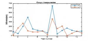
Figure 13: Pozyx Inaccuracies by Differences
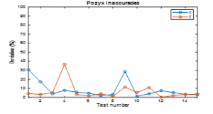
Figure 14: Pozyx Inaccuracies by Deviation
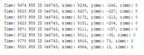
Figure 15: Pozyx Negative Values
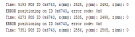
Figure 16: Pozyx Delay
4. Conclusions and Recommendations
This work involves software design and hardware adaptation of collision avoidance of autonomous vehicles simultaneously crossing an intersection. Hardware implementation was done by using small-scaled RC cars with attached Pozyx where test cases were done. The accuracy of the Pozyx was tested and verified. Upon running the various test cases to verify the system with different car placements and maneuvers, it was observed that the Pozyx module had issues in location accuracy and delay between updates that impede in determining the accurate location of each car in the track.
Recommendations include incorporation of machine learning in AV and autonomous intersection management, implementation of software simulation in different programming languages, an extension of hardware implementation on large-scale vehicles, and to some extent, real vehicles and crossroads. Moreover, it is suggested to use uninterrupted, fast, and accessible communication technologies. Communication among AVs with the central computer system can be extended by using accurate and efficient road map data exchange and cloud databases. Expanding the model of the car’s movement from linear acceleration to a more dynamic model would greatly improve the accuracy of the resultant predetermined coordinates, and consequently, more appropriate car commands. Besides, more sensors that can keep track of attributes not necessarily related to motion would be a useful feature.
Conflict of Interest
The authors declare no conflict of interest.
Acknowledgment
De La Salle University is acknowledged for supporting this work.
- E. A. Smith, Statistics on Intersection Accidents. 2018. https://www.autoaccident.com/statistics-on-intersection-accidents.html
- R. Ewing, Traffic Calming State of the Practice. 1999. https://nacto.org/wp-content/uploads/2012/06/Ewing-Reid-1999.pdf
- N. Kazis, To Get Safer Streets, Traffic Lights and Stop Signs Aren’t the Answer. 2011. https://nyc.streetsblog.org/2011/04/26/to-get-safer-streets-traffic-lights-and-stop-signs-arent-the-answer
- K. F. Chu, E. R. Magsino, I. W.-H. Ho, and C.-K. Chau, “Index Coding of Point Cloud-Based Road Map Data for Autonomous Driving,” in 2017 IEEE 85th Vehicular Technology Conference (VTC Spring), 2017, 1–7, 2017. doi: 10.1109/VTCSpring.2017.8108280.
- I. W.-H. Ho, S. C.-K. Chau, E. R. Magsino, and K. Jia, “Efficient 3D Road Map Data Exchange for Intelligent Vehicles in Vehicular Fog Networks,” IEEE Transactions on Vehicular Technology, 69(3), 3151–3165, 2020, doi: 10.1109/TVT.2019.2963346.
- “Home | Pozyx.” https://www.pozyx.io/. 2020.
- J. Pereira, H. Gomes, S. Mendes, R. Santos, S. Faria, and C. Neves, “Long range RFID indoor positioning system with passive tags,” in Industry 4.0–Shaping the Future of The Digital World: Proceedings of the 2nd International Conference on Sustainable Smart Manufacturing (S2M 2019), 9–11 April 2019, Manchester, 112, 2020. doi: 10.1201/9780367823085-21.
- Y.X. Wang and C.-L. Chang, “ROS-base Multi-Sensor Fusion for Accuracy Positioning and SLAM System,” in 2020 International Symposium on Community-centric Systems (CcS), 1–6, 2020. doi: 10.1109/CcS49175.2020.9231442.
- V. Di Pietra, N. Grasso, M. Piras, and P. Dabove, “Characterization of a Mobile Mapping System for Seamless Navigation,” The International Archives of Photogrammetry, Remote Sensing and Spatial Information Sciences, 43, 227–234, 2020. doi: 10.5194/isprs-archives-XLIII-B1-2020-227-2020.
- C. Siebert, P. R. DeStefano, and R. Widenhorn, “Teaching physics with a local positioning system,” The Physics Teacher, 57(6), 428–429, 2019. doi: 10.1119/1.5124294.
- SAE International and S. O.-R. A. V. S. COMMITTEE, “Surface Vehicle Information Report: Taxonomy and Definitions for Terms Related to On-Road Motor Vehicle Automated Driving Systems,” Jan. 2014.
- K.-M. Mimoune, I. Ahriz, and J. Guillory, “Evaluation and improvement of localization algorithms based on uwb pozyx system,” in 2019 International Conference on Software, Telecommunications and Computer Networks (SoftCOM), 1–5, 2019. doi: 10.23919/SOFTCOM.2019.8903742.
- K. Dresner and P. Stone, “A Multiagent Approach to Autonomous Intersection Management,” Journal of Artificial Intelligence Research, 31, 591–656, 2008.
- T.-C. Au, S. Zhang, and P. Stone, “Autonomous Intersection Management for Semi-Autonomous Vehicles,” Handbook of Transportation, 88–104, 2015.
- Vehicle Turning Paths Dimensions and Drawings. Dimensions.Guide https://www.dimensions.guide/collection/vehicle-turning-paths-radius