An Adaptive Nonlinear Sensorless Controller of Doubly Fed Induction Generator Driven By Wind Turbine

Adv. Sci. Technol. Eng. Syst. J. 5(6), 489–496 (2020);
 DOI: 10.25046/aj050658
In this study, an adaptive nonlinear sensorless controller for doubly fed induction generator (DFIG) driven by a wind turbine is proposed. The aim is to maximize the extracted power by tracking the wind turbine optimal torque-speed characteristic without the need for rotor speed measurement. This controller ensures a satisfactory tracking of both stator flux and rotor speed. It considers the detailed model of DFIG in an arbitrary (d–q) rotating frame without any simplifying assumption. An observer provides the rotor speed estimation incorporated in the control loop. To guarantee the system stability under parametric uncertainties like the aerodynamic torque and the rotor winding resistance, which harms the efficiency and the robustness of the controller, update laws are established to estimate the uncertain parameters. Lyapunov’s theory is used to prove the system stability. The proposed adaptive sensorless controller validity is demonstrated by simulation in Matlab/Simulink environment. The robustness of the controller is confirmed by the comparison between the same controller with and without adaptation.
1. Introduction
Recently, using wind energy to produce electricity has been gradually grabbing the attention of many researchers, thanks to its cleanliness and dependability. Because of its smaller power electronic components rating and its wide speed operation range, the DFIG is seen as the most used wind turbine generator [1–3]. The DFIG rotor windings are connected to the electrical grid via rotor and grid side converters (RSC and GSC) and RL filter, whereas the stator windings are immediately related to the electrical grid as illustrated by Figure 1. In the last decade, many researchers giving much focus and interest to the field of sensorless control of DFIG-based wind turbine (DFIG-WT)[4–7]. In this control strategy, the DFIG-WT systems operate without the need to use the speed sensor, which lowers the whole system cost and enhance its overall reliability by minimizing the number of components that are susceptible to failure.
There has been some research about sensorless control using proportional-integral (PI) loops such as [8,9]. The latter mainly relied on assumptions that the flux or stator voltages are constant, and the stator resistance is negligible. However, these assumptions are useless under grid faults or load variations. Furthermore, the small resistance of the stator may cause an incorrect damped dynamics of the stator flux [10].
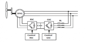
Figure 1: Schematic representation of grid connected DFIG-WT system
For the most control strategies, if the actual values do not correspond to the parameters and variables of DFIG-WT used in the control law, it could result in a failure of the closed-loop control. So, when some parameters and variables are difficult to be measured, some strategies based on estimation theory are important to generate a pertinent control. The frequency, the temperature and the magnetic saturation may cause the change of DFIG parameters [11]. Therefore, the online parameter estimation or disturbance observer is compulsory to have high precision control.
Much research has addressed the control of DFIGs during parameter variation [12–14]. On the other hand, the modeling and the control of WT is not an easy task, particularly when large scale WTs, in megawatts, are considered [15,16]. Hopefully, to minimize the drive train vibration and to develop the quality of the extracted power, some works use the estimation theory in order to take into consideration the uncertainties arose from the aerodynamic torque, particularly in the stage of the maximum power point tracking (MPPT) [17].
The main focus of this work is to elaborate an adaptive sensorless control for the rotor side converter (RSC), this controller takes into consideration the detailed model of DFIG. Update laws in real-time are established to deal with the parameter uncertainties. To preserve the objectives of the MPPT without the need to use rotor speed sensor , a speed observer is incorporated in this controller. The remaining of this research paper displays as follows: The second section revolves around the model of the DFIG-WT system. The third section puts forward the suggested nonlinear controller: For the start, we present the proposed rotor speed observer. Afterward, we introduce our sensorless controller design, and we point out to the control laws of DFIG, and update laws for the speed observer, as well as the estimated rotor resistance and aerodynamic torque, which are competed using the Lyapunov theory. The last section considers simulation results and discussion. At last, we wrap up by drawing some concluding remarks.
2. DFIG-WT model
2.1. Wind turbine model
Based on wind turbine aerodynamic[18], The power captured from the wind can be expressed as :
![]()
where is the air density, is the blade radius and is the wind speed. The wind power coefficient depens on the design the blades; is a function of pitch angle and tip speed ratio (TSR).
where:
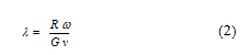
In which is the mechanical generator speed and is the gearbox ratio. In the basis of the wind turbine design [18], the expression of power coefficient is:

The coefficients c1-c6 are listed in Table 1.
Table 1: Values of coefficients c1-c6
| 0.5176 | 116 | 0.4 | 5 | 21 | 0.0068 |
When the pitch angle remains unchanged, there is an optimum tip ratio that maximizes the power coefficient , In this study, we assume that .So the MPPT is achieved by the control of the generator speed. Conforming to (2) the mechanical speed that optimize the extracted power is:
![]()
2.2. Induction generator model
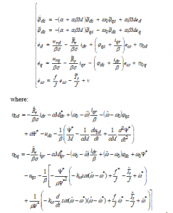
Employing the flux-linkage and voltage equations of the induction generator [19], the state variables of DFIG in an arbitrary reference frame rotating at speed include d-q rotor currents and stator fluxes , , and generator speed .The considered 5th-order state-space representation of DFIG can be expressed as:
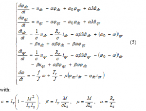
is the mechanical torque. The rest of the parameters of DFIG-WT system are given in Table 2, Appendix B.
3. Control design
3.1. Speed observer
Achievement of MPPT strategy requires a quick convergence of the mechanical rotor speed to its optimal value. An observer is proposed to estimate the actual rotor speed of DFIG.
![]()
Measurement of the rotor currents and the stator fluxes are compulsory for the latter observer; it relies also on the estimated aerodynamic torque and the term which will be elaborated by the means of the Lyapunov approach.
3.2. Reference Signals
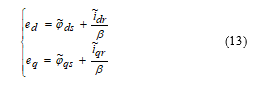
Supposing that; the d-q rotating frame is aligned with the stator flux vector as in [20]. In our case, we consider that the stator flux vector is associated with the d-axis of the d-q reference frame giving:
![]()
Based on the assumption (7) illustrated by Figure 2, the expressions of the reference signals in the steady-state condition of DFIG can be established:
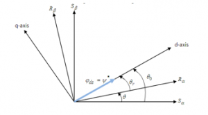
Figure 2: Determination of angles for the DFIG in d-q reference frame
Taking into consideration the latter assumption (7), and according to the first equation of (5), the reference of the direct rotor current can be expressed as follows:
![]()
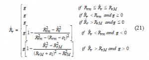
From the 5th equation of the system (5), the reference of the quadratic rotor current is established by replacing the aerodynamic torque by its estimate and incorporating a feedback saturation function [21], which relies on the estimated and reference rotor speed:
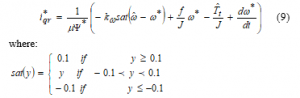
The saturation function sat(y) has a finite limit at infinity; it is a linear, odd, and differentiable function in a neighborhood of the origin. To satisfy the assumption (7), the d-q reference frame must rotate at a specific speed which is expressed using the second equation of (5):
![]()
3.3. Control and update laws
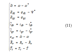
The rotor speed sensor has some weak points concerning robustness, maintenance, cost, and cables linking the speed sensor and the control block. Any incorrect value provided by the rotor speed sensor may significantly harm the defined control targets and it can also destroy the system stability. Besides, accurate modeling of the aerodynamic torque is not an easy task, and the rotor winding resistance may vary up during operation due to the heating of the generator. That is to say that it constitutes uncertain parameters for the model which can affect the system stability. Yet, to ensure the system stability and maintain the control objectives in the presence of uncertainties and without needing to measure the rotor speed, the system closed-loop stability is examined to extract the expressions of the additional term used in the speed observer, and the update laws of the estimated rotor resistance and aerodynamic torque. In this study, we assume that the aerodynamic torque and rotor resistance are unknown and vary slowly with time and should be estimated. To this purpose, the error variables can be introduced as follows:
Using equations (5), (6), (7), (8), (9), (10) and (11) the system of the error dynamics can be expressed as follows:
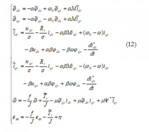
In order to have a compact error dynamic system, the error variables and are considered instead of and :
The error dynamics in (12) becomes:
The expression of the stator direct voltage derivative is detailed in Appendix A. we construct a Lyapunov function for the system (14) as:

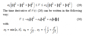
where , and are positive design parameters given in Appendix B. The derivative of along with the time gives

where is the projection algorithm[22], which is specified in our case by
with and are the upper and the lower bound values of , respectively, and is an arbitrary positive constant such that .
We define the update laws of the additional term and the aerodynamic torque as

with is the upper bound value of and is an arbitrary positive constant. Substituting (18), (19), (21), (22) and (23) in (16), the time derivative of (15) becomes:
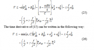
Since and has been designed using a projection algorithm (bounded), from (15) and (26) we can establish that the functions , , , and are bounded on . Consequently, from (14) it’s clear that , , , and are bounded on . So the functions , , , and are uniformly continuous on , as a result, from(13) it can be seen that , , and are bounded, and the functions , are also uniformly continuous on .
The closed loop of the system (14) is determined based on (19), (21), (22) and (23) as:

We can put the last five equations of (27) in the following form:

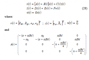
with are bounded functions such that
Since the functions are bounded, so for all , , , , , and are bounded, with , , , , , ,
From (15), the function can be put into the following inequation:
with:
According to the proof of lermma 2.1 in [23], the origin of (28) is locally exponentially stable.
4. Simulation Results
Simulation of the detailed model of 3MW DFIG-WT using the proposed adaptive nonlinear sensorless controller is performed in MATLAB/Simulink environment, the parameters and characteristics of the latter DFIG-WT along with the design parameters are given in Table 2, and Table 3, Appendix B.
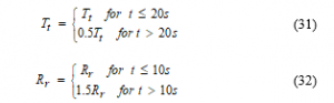
The estimation and tracking performance of the adaptive sensorless controller is shown using a variable wind speed of mean value as depicted in Figure 3. To show the robustness of the proposed adaptive sensorless controller against the aerodynamic torque and the rotor winding resistance variation the tracking performance for both the sensorless controller with [24] and without adaptation at constant wind speed has been compared in Figure 4. The simulation is performed with the variation of the mechanical torque and the rotor winding resistance described by:
From Figure 3 (a) and 3 (b) the actual rotor speed varies in accordance with the wind speed, which confirms the effectiveness of the MPPT. Figure 3 (c) shows a good tracking performance of the stator quadratic current. According to Figure 3(d) it can be noticed that the estimated torque recovers the applied unknown torque. Similarly, from Figure 3(e) it can be observed that the estimated rotor resistance quickly converges to its true profiles. In Figure 4 the adaptive nonlinear sensorless controller performance is shown by the comparison of the proposed adaptive sensorless and the sensorless controller proposed in [24]. From Figures 4 (a) and 4 (b) it is noted that the stator flux and the rotor speed tracking errors sustain small perturbations caused by the unknown rotor resistance and the unknown aerodynamic torque, but they converge to zero quickly as soon as the estimates of , and converges to their actual values. Whereas in the case of control without adaptation Figures 4 (c) and 4 (d) the rotor speed and the stator flux don’t track anymore their references after variation of the rotor resistance and the aerodynamic torque.
When the actual values do not correspond to their references, the closed loop system is exposed to failure, which destroys the control objectives. These results confirm the robustness of our controller regarding to the rotor resistance variation along with the aerodynamic torque.
5. Conclusion
This paper presents an adaptive nonlinear sensorless controller for DFIG-WT to maximize the wind energy extracted under parametric uncertainties and unknown rotor speed. The simulation performed in Matlab/Simulink environment illustrates the good results provided by the controller regarding the good tracking capability of the rotor speed and stator flux, in addition to correct estimation of the unknown rotor speed, aerodynamic torque, and the rotor resistance. Also, the comparison result between the same controller with and without adaptation shows the effectiveness of this work.
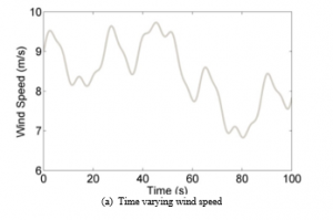


Figure 3: Comparison of tracking performance s under unknown parameters Changes occur at t=10s , t=10s and at t=20s
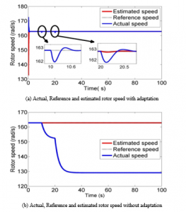
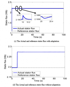
Figure 4: Comparison of tracking performances under unknown parameters Changes occur at t=10s , t=20s
- G.M. As, “Doubly fed induction generator uising back-to-back PWM converters and its application to variable- speed wind-energy generation,” 1996.
- S. Müller, M. Deicke, R.W. De Doncker, “Doubly fed induction generator systems for wind turbines,” IEEE Industry Applications Magazine, 8(3), 26–33, 2002, doi:10.1109/2943.999610.
- G. Boroumandjazi, B. Rismanchi, R. Saidur, “Technical characteristic analysis of wind energy conversion systems for sustainable development,” ENERGY CONVERSION AND MANAGEMENT, 69, 87–94, 2013, doi:10.1016/j.enconman.2013.01.030.
- A.B. Ataji, Y. Miura, T. Ise, H. Tanaka, “A Rotor-Current-Based Slip Angle Estimator for Grid-Connected Doubly Fed Induction Generator Requiring the Stator Inductance only,” IEEE Transactions on Power Electronics, 32(6), 4827–4838, 2017, doi:10.1109/TPEL.2016.2598441.
- L.Y. Lu, N.F. Avila, C.C. Chu, T.W. Yeh, “Model Reference Adaptive Back-Electromotive-Force Estimators for Sensorless Control of Grid-Connected DFIGs,” IEEE Transactions on Industry Applications, 54(2), 1701–1711, 2018, doi:10.1109/TIA.2017.2765300.
- M.W. Kalaga Mbukani, N. Gule, “Comparison of high-order and second-order sliding mode observer based estimators for speed sensorless control of rotor-tied DFIG systems,” IET Power Electronics, 12(12), 1–11, 2019, doi:10.1049/iet-pel.2018.6225.
- R.M. Prasad, M.A. Mulla, “Position-sensorless direct torque control of grid-connected DFIG with reduced current sensors,” Sadhana – Academy Proceedings in Engineering Sciences, 45(1), 2020, doi:10.1007/s12046-020-1275-x.
- H. Becheri, I.K. Bousserhane, A. Harrouz, I. Colak, K. Kayisli, “Sensorless Control of Wind Turbine Conversion Equipped with a DFIG Using MPPT Strategy,” Proceedings – 2018 IEEE 18th International Conference on Power Electronics and Motion Control, PEMC 2018, (3), 605–610, 2018, doi:10.1109/EPEPEMC.2018.8522002.
- E.H. Abdou, A.R. Youssef, S. Kamel, M.M. Aly, “Sensorless Wind Speed Control of 1.5 MW DFIG Wind Turbines for MPPT,” 2018 20th International Middle East Power Systems Conference, MEPCON 2018 – Proceedings, 700–704, 2019, doi:10.1109/MEPCON.2018.8635209.
- B. Yang, L. Jiang, L. Wang, W. Yao, Q.H. Wu, “Nonlinear maximum power point tracking control and modal analysis of DFIG based wind turbine,” International Journal of Electrical Power & Energy Systems, 74, 429–436, 2016, doi:10.1016/j.ijepes.2015.07.036.
- G.E.-P. and R.E.-P. López-García , F. Beltran-Carbajal, “A Review of RFO Induction Motor Parameter Estimation Techniques,” 18(2), 271–283, 2003.
- J.M. Mauricio, A.E. Leon, A. Gomez-Exposito, J.A. Solsona, “An Adaptive Nonlinear Controller for DFIM-Based Wind Energy Conversion Systems,” IEEE Transactions on Energy Conversion, 23(4), 1025–1035, 2008.
- A. Susperregui, I. Lizarraga, J. Jugo, G. Tapia, “Automated control of doubly fed induction generator integrating sensorless parameter estimation and grid synchronisation,” IET Renewable Power Generation, 8(1), 76–89, 2014, doi:10.1049/iet-rpg.2013.0045.
- R. Ourhdir, M. Rachidi, “Adaptive input-output feedback linearization control of doubly-fed induction machine in wind power generation,” International Review of Automatic Control, 12(1), 11–20, 2019, doi:10.15866/ireaco.v12i1.15619.
- J.M. Pinar Pérez, F.P. García Márquez, A. Tobias, M. Papaelias, “Wind turbine reliability analysis,” Renewable and Sustainable Energy Reviews, 23(March), 463–472, 2013, doi:10.1016/j.rser.2013.03.018.
- X. Jin, W. Ju, Z. Zhang, L. Guo, X. Yang, “System safety analysis of large wind turbines,” Renewable and Sustainable Energy Reviews, 56, 1293–1307, 2016, doi:10.1016/j.rser.2015.12.016.
- F. Liu, D. Li, P. Li, Y. Song, “Quadratic Optimal Tracking Control of Wind Turbine Systems,” IFAC-PapersOnLine, 48(28), 502–507, 2015, doi:10.1016/j.ifacol.2015.12.178.
- S. Heier, GRID INTEGRATION OF WIND ENERGY GRID INTEGRATION OF WIND ENERGY ONSHORE AND OFFSHORE.
- I. Press, L. Shafer, G.W. Arnold, D. Jacobson, ANALYSIS OF ELECTRIC MACHINERY AND DRIVE SYSTEMS.
- G. Abad, J. López, M.A. Rodríguez, L. Marroyo, G. Iwanski, Doubly Fed Induction Machine: Modeling and Control for Wind Energy Generation, 2011, doi:10.1002/9781118104965.
- R. Marino, P. Tomei, C.M. Verrelli, Induction Motor Control Design, 2010, doi:10.1007/978-1-84996-284-1.
- L. Praly, “Adaptive Nonlinear Regulation: Estimation from the Lyapunov Equation,” IEEE Transactions on Automatic Control, 37(6), 729–740, 1992, doi:10.1109/9.256328.
- R. Marino, G.L. Santosuosso, P. Tomei, “Robust adaptive observers for nonlinear systems with bounded disturbances,” IEEE Transactions on Automatic Control, 46(6), 967–972, 2001, doi:10.1109/9.928609.
- R. Ourhdir, M. Rachidi, “Nonlinear sensorless control of doubly fed induction generator in wind power generation,” 2020 1st International Conference on Innovative Research in Applied Science, Engineering and Technology, IRASET 2020, 2(1), 2020, doi:10.1109/IRASET48871.2020.9091997.