Fault-Tolerant Control of Permanent Magnet Synchronous Motor Drive under Open-Phase Fault
Volume 5, Issue 6, Page No 455-463, 2020
Author’s Name: Amr Saleh1,a), Nada Sayed2, Ghada Ahmed Abdel3, Mona Nagieb Eskander3
View Affiliations
1Electrical Engineering Department, Faculty of Engineering, Fayoum University, Fayoum, 63514, Egypt
2Engineering Mathematics and Physics Department, Faculty of Engineering, Fayoum University, Fayoum, 63514, Egypt
3Power Electronics and Energy Conversion Department, Electronics Research Institute, Cairo, 12622, Egypt
a)Author to whom correspondence should be addressed. E-mail: aae00@fayoum.edu.eg
Adv. Sci. Technol. Eng. Syst. J. 5(6), 455-463 (2020); ![]() DOI: 10.25046/aj050654
DOI: 10.25046/aj050654
Keywords: Fault Diagnostic, Fault Tolerant Control, Field Oriented Control, Open Phase Fault, PMSM

Export Citations
This paper presents an integrated solution for a fault-tolerant three-phase permanent magnet synchronous motor (PMSM) field-oriented control drive subjected to an open-phase fault (OPF) integrated with effective fault-tolerant detection methodology. The fault detection methodology is based on model predictive current control (MPCC), which is easy to apply, detect OPF in a range of microseconds, and robust under-speed or load transient. On the other hand, the fault-tolerant compensation is based on a neutral point connection together with stator current regulation to maintain the magneto-motive force (MMF) unchanged under open-phase failure. Controlling the motor phase currents in the post-fault condition ensures a rotating magnetic field similar to that produced during healthy conditions thus, reducing the saturation impact and ensuring the reliability of the control operation. The proposed integrated fault-tolerant drive is validated using MATLAB simulation that ensure the effectiveness of the proposed solution in steady state and during transients under different loading and rotor speed condition.
Received: 27 August 2020, Accepted: 15 October 2020, Published Online: 20 November 2020
1. Introduction
Permanent magnet synchronous motor (PMSM) is employed when high torque density/volume is needed, including systems with high safety requirements [1], [2]. As the more complexity of the electrical drives become, the possibility of system faults and failures increases which are hard to be prevented and can lead to severe effects. Fault-tolerant (FT) capability is the main requirement of motor drives in various applications such as electric vehicles, aerospace and spacecrafts, as the reliability of the motor drive system is very critical [3]. Such a system should identify faults, locate their origin, and, if possible, continue to operate after the fault happens. The Fault-tolerant control scheme involves fault detection and compensation. The open-circuit fault may not cause instantaneous damage and can even remain undetected for long periods thus leading to secondary failures [4]. The open-phase fault (OPF) happens in electrical machine drives when a winding phase is disconnected or one inverter leg fails or even due to a protection system isolating a short-circuit condition. In this situation, a large ripple of electromagnetic torque is created and serious mechanical vibration may happen. Fast and accurate methods of detection and fault-tolerance are therefore urgently needed to identify, isolate the fault early, and prevent the destruction of the whole system [5].
Among the numerous techniques for identifying faults by sensing waveforms is the Machine Current Signature Analysis (MCSA) which is based on Fast Fourier transform (FFT) stator current analysis but is limited to steady-state process and requires stator current monitoring for at least one or more electrical post-fault periods before detecting the fault successfully. It also needs substantial processing energy and memory resources. Another technique known as Park’s vector approach relies on the analysis of stator current in the rotor reference frame [6]. The current trajectories have a circular shape in normal conditions, the trajectories shape changes to the ellipse in the case of open phase fault (OPF). Modifications and developments of this technique are presented in [7]. These methods are much simpler and faster than MCSA, but during transient speed and load, they are subject to false alarms. In [8], a model reference adaptive system (MRAS) detection technique has been presented which relies on voltage monitoring and model current calculation when a fault happens in the steady-state; the threshold value of the detection was estimated empirically. The model predictive current control (MPCC) that has been presented for fault diagnostic in PMSM [9], [10] is employed here, where it relies on the stator current prediction and estimated error. MPCC scheme for the fault detection is found to be fast, requires minimum processing effort and robust under transient conditions.
Fault-tolerant control (FTC) compensation techniques for OPF PMSM drives have been introduced in two major forms depending on whether reconfiguration in hardware is needed or not. Methods with reconfiguration [11] are most applicable due to the fact that single-phase operation of the method without reconfiguration [9] even with modifications applied has the probability of matching the system mechanical resonance frequency at low speeds. One of the reconfiguration methods with extra inverter leg connected to the neutral point of PMSM is presented in [12], however still the main drawback of this method is the extra complexity of the power converter and additional cost and size. In [13] the authors employed a fourth leg in a manner that it replaces the faulty leg, yet the same drawback of extra complexity and additional cost and size remains the same. In [14] fault-tolerant systems of five-phase permanent magnet motor drive was studied. However, the multiphase machines are not a suitable solution in some application owing to the extra weight and costs. In this paper, the FTC compensation methodology implemented is targeting a lower cost compensation methodology [15], however, the magnitude of the phase current is limited to its permissible limit in order to minimize saturation impacts and ensure a sustainable motor drive fault-tolerant operation [16].
It is commonly found in literature research efforts that are dedicated for the fault detection [6]- [9] and others that present the fault compensation methodology [11]-[15], while it is rarely presented in the literature papers that provide complete solution from the instant of open phase fault, it is detection until applying the fault compensation methodology
In this paper the authors are introducing an integrated solution for a field oriented controlled PMSM drive that incorporates the benefits of fast open phase fault detection using a methodology based on MPCC and a reconfiguration fault compensation method that utilizes minimum additional hardware achieving a balanced operation with balanced current in magnitude thus dramatically reduces the torque ripples and consequently the ripples in the rotor speed as presented in [15]. In contrary to using a pulse width modulator in [15], the authors here deduced the required transformation to apply a space vector modulator which provides less harmonic distortion.
The paper is arranged as follows, Section 2 presents the modeling of PMSM, Section 3 presents the concept of the field-oriented control (FOC) of PMSM, Section 4 presents the concept of the MPCC used for OPF detection, Section 5 describes the proposed FTC compensation strategy and Section 6 shows the simulation results. Finally, Section 7 provides the conclusion of this work.
2. PMSM Mathematical Model
The electrical dynamic equations of the PMSM in the abc stationary reference frame can be written as [15], [17]:
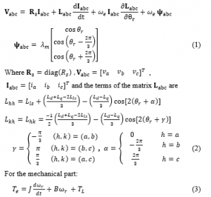
is the load torque, B is the damping coefficient, is the rotor mechanical speed and J is the moment of inertia.
The electromagnetic torque can be represented as in (4):
![]()
For the loss of one phase, the current in the lost phase becomes equal to zero keeping a single-phase current circulating in the remaining two phases.
For the post fault operation with the neutral of the star-connected three-phase windings of the PMSM connected to the center point of the DC link, the PMSM equations can be re-written as in [15]:

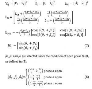
The torque consists of two-component: reluctance torque (Ter)
and excitation torque (Tem) that is expressed in (9) and (10):
3. Field oriented control (FOC) of PMSM
The FOC method used for AC electrical machine is concerned to let the AC machine behaves like the dc machine in terms of decoupled torque and flux control. A FOC control algorithm is manipulating the stator current vector in a d-q reference frame attached to the rotor. The torque equation of the PMSM in a d-q reference is given as:
![]()
Keeping the direct component of the stator current vector equals to zero results in a torque that is controlled through the manipulation of the quadrate component of the stator current vector. is the permanent magnet flux linkage resembling the flux in the DC machine so the torque can be expressed as:
![]()
FOC has the advantage of having a fast response and little torque ripple.
4. MPCC method for OPF detection
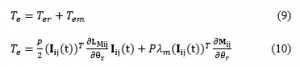
The model predictive current control (MPCC) applied for fault diagnostic relies on the stator current prediction and estimated error to detect the abnormal situation. The current prediction is derived from the stator voltage equations in the d −q reference frame of the machine attached to the rotor (rotor field) as given in (13) and (14) [9], [10].

By simplifying the derivation of the predicted current from (13) and (14), justified by the short sampling interval of Δt, the rotor speed ωe can be considered to be quasi-constant, and linear change of stator currents during the short sampling interval [9].The PMSM equations can, therefore, be discretized with Euler approximation, resulting in the prediction of stator current at the sample as given below:
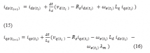
The objective function is chosen at the sampling time ti, as the sum of the squared errors between the predictive values of d– and q-axis currents and their corresponding actual values as expressed in (17) [10]:
![]()
where E is considered to be the fault indicator. Under normal conditions and without system failure, E is relatively small within the expected range, once a fault occurs, the value of E will increase in magnitude exceeding the error threshold Eth. The chart in Figure 1 shows how the proposed algorithm differentiates between actual fault condition and transient operation condition. In this algorithm, the condition of having one of the phases with zero measured current and zero predicted current fulfills the condition of OPF. Few sampling intervals are sufficient to detect the fault. The proposed solution has the following advantages:
- The OPF can be identified rapidly, in a range of few sampling intervals that are in the order of µsec.
- No considerable processing power is needed.
- Effective during transient speed and load.
5. The fault-tolerant compensation topology
Between many configurations, the minimum level of fault-tolerance in a three-phase drive for an OPF can be accomplished by isolating the faulty element, opening the corresponding motor phase, and connecting the motor stator neutral point to the mid-point of the inverter dc bus [15], as shown in Figure 2. During the OPF, after the system detects the abnormal condition (OPF) the system firstly disconnects the faulty phase leg by disabling the PWM signals to the corresponding switches of the inverter to avoid its impact on drive behavior after applying the post fault strategy, then fault compensation technique should begin and can be split into two steps as follows:
- Connect the PMSM neutral to the mid-point of DC bus by firing TRn to continue the machine operation as a two-phase motor as illustrated in Figure 2.
- Apply the post-fault current regulation technique as will follow in this section.
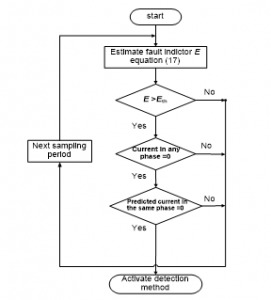
Figure 1: Flow chart of MPCC
For the PMSM FOC drive, in the healthy operation, the stator phase current has two components iqs, ids, representing the torque and the flux components, respectively. During the postfault stage, the motor neutral to the mid-point of the DC link split the machine phase currents into two currents where the zero-sequence component of the phase current becomes active, i.e. ΣIn≠0. The fault-tolerant control strategy [11], [15] targets to maintain the same magneto-motive force (MMF) of the three-phase healthy operation and balance the unbalanced open-phase fault operation. This can be achieved by the following transformations to obtain the set of reference voltages for the remaining two healthy phases as follows:

Also, similar matrices A, B, and RI instead of Rv are used to transform the phase currents.
Where,

And S is the transformation between the balanced alpha-beta frame and the alpha-beta reference frame of the SVPWM given as:
![]()
Then the resulting two-phase post fault currents will increase to of the healthy phase current with phase angle shifted 60о away from each other [11], [12]. This is illustrated by the phasor diagram in Figure 3 for an OPF in phase (a).

Figure 2: FTC motor drive configuration
This ensures the same rotating magnetic field and thus the same stator flux linkage by maintaining the same MMF between healthy and fault-tolerant conditions. The compensation of voltage drops due to the variation of stator resistance [11] was also applied to remove their effect during the fault-tolerant operation as shown in Figure 4. The flow chart in Figure 5 summarize applied post fault compensation methodology.
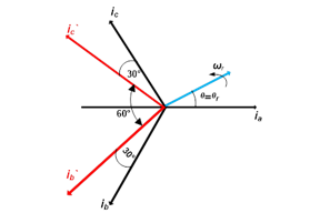
Figure 3: The phasor diagram of the PMSM under OPF

Figure 4: The proposed FTC system for the PMSM drive
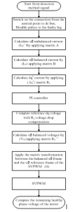
Figure 5: Flow chart of fault compensation control steps
6. Simulation results
In this section, MATLAB simulation results are presented from a MATLAB Simulink model developed for the PMSM drive system in Figure 4 with proposed fault detection and fault-tolerant techniques under different modes of operation (healthy, during an open-phase fault, fault-tolerant compensation). Four cases under the different conditions and with different speed and load conditions as presented in Table 2. The PMSM parameters are listed in Table 1.
Table 1: Three Phase PMSM Parameters
| Value | Parameter |
| 0.47 kw | Rated power |
| 2.2 N.m. | Rated torque |
| 2 A | Rated current |
| 1000 rpm | Rated speed |
| 3 | The number of pole pairs (p) |
| 0.000198 kg.m2 | Moment of inertia coefficient |
| 5.95 Ω | Stator Resistance (Rs) |
| 12.5 mH | d-axis Inductance (Ld) |
| 12.5 mH | q-axis Inductance (Lq) |
| 0.2955556 Wb | The PM flux linkage ( ) |
Table 2: Test cases
| Description | Cases |
| In this case phase b is disconnected, detection method (MPCC) is disabled; reference speed 1000 rpm, and load torque 0.5 N.m. | A |
| In this case phase b is disconnected, detection method (MPCC) is disabled, reference speed 500 rpm, and load torque 1 N.m. | B |
| In this case phase b is disconnected, the detection method (MPCC) enabled, reference speed 400 rpm and load torque 1 N.m. | C |
| In this case of phase, b is disconnected, detection method (MPCC) is enabled, with transient speed change from 400 rpm to 800 rpm and load torque 1 N.m. | D |
- phase b is disconnected, detection method (MPCC) is disabled; reference speed 1000 rpm, and load torque 0.5 N.m.
The PMSM is first driven at healthy operating conditions. An OPF at phase b is then applied at t=0.1 sec with the fault detection subsystem being disabled for illustrating the error signal that is used for detecting the fault when the integrated fault detection, fault-tolerant compensation technique is fully applied. At t = 0.2 sec, The FTC current regulation technique is allowed to start thus, connecting the neutral point to the mid-point of the DC link and applying the required modification for the current control to return back the magneto-motive force to its value during the healthy operation as explained in section 5. Figure 6 shows the stator currents during the OPF in phase b at t = 0.1 sec, the phase b current falls to zero while the other two-phase currents have the same value of the current, but with opposite polarity (phase-shifted 180°). When the FTC compensation is applied at t = 0.2 sec, the currents of the remaining healthy phases is increased in magnitude by 1.73 and shifted 60° apart from each other.

Figure 6: Stator currents before, during the fault and after FTC compensation (case A)
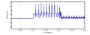
Figure 7: Fault detection error magnitude before, during the fault and after FTC compensation (case A)
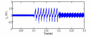
Figure 8: d-axis current before, during the fault and after FTC compensation (case A)

Figure 9: q-axis current before, during the fault and after FTC compensation (case A)

Figure 10: Rotor speed before, during the fault and after FTC compensation (case A)
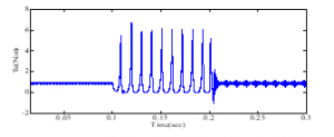
Figure 11: Electromagnetic torque before, during the fault and after FTC compensation (case A)
During the OPF the error magnitude increases due to the OPF (t = 0.1sec – 0.2 sec) then back to the acceptable range after the FTC technique is applied (t = 0.2sec – 0.3sec) as presented in Figure 7. The dq currents, speed, and torque ripples severely increase during the fault due to the OPF operation, then the FTC technique constrained it as shown in Figure 8, Figure 9, Figure 10, and Figure 11.
- Phase, b is disconnected, detection method (MPCC) is disabled, reference speed 500 rpm, and load torque 1 N.m.
During single-phase operation (OPF occurs at t= 0.1 sec) without enabling the detection technique (MPCC), the system cannot identify the fault and this leads to the PMSM stop and cannot continue its operation. Until the FTC compensation is applied at (t=0.2 sec), PMSM can return back to work with the remaining two phases at t=0.2 sec a Shown in Figures 12, 13 and14.
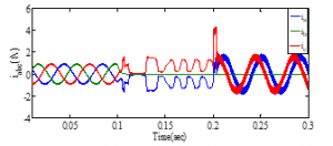
Figure 12: Stator currents before, during the fault and after FTC compensation (case B)
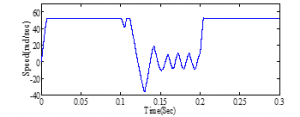
Figure 13: Rotor speed before, during the fault and after FTC compensation (case B)
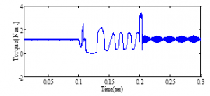
Figure 14: Electromagnetic torque before, during the fault and after FTC compensation (case B)
- phase b is disconnected, the detection method (MPCC) enabled, reference speed 400 rpm and load torque 1 N.m.
Phase b is opened at 0.1 sec with the fault detection technique (MPCC) enabled. The function of the fault detection method is to detect the OPF and trigger the FTC-compensation for operation. It is obvious from Figures 15 to 20 that the detection of the OPF is only in a few µsec depending on the error indicator. In normal operation (t = 0 – 0.1sec) the error as given in (17) is close to zero, at the instant of fault at (t= 0.1 sec) the error magnitude is increased and the MPCC detects it quickly before the error value becomes high. Once the fault detection takes place it activates the FTC which returns back the error value to an expected range (t= 0.1 – 0.3 sec) as shown in Figure 16. The stator currents are depicted in Figure 15. As shown in Figure 17 and Figure 18, the balance in the resultant MMF can be easily observed by obtaining the same average torque and speed as in the healthy operation at the instant the fault is detected and FTC is activated. ids and iqs are depicted in Figure 19 and Figure 20, respectively. Comparing case C to case B, it can be concluded that the fast response of the fault detection prevents the drive from halting at low-speed operation.
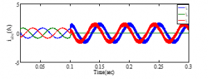
Figure 15: Stator currents in the healthy and post-fault operation

Figure 16: Fault detection error magnitude in the healthy and post-fault operation

Figure 17: Electromagnetic torque in the healthy and post-fault operation

Figure 18: Rotor speed in the healthy and post-fault operation
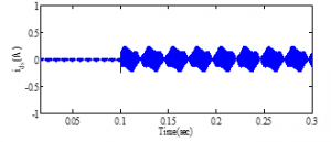
Figure 19: d-axis current in the healthy and post-fault operation
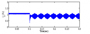
Figure20.: q-axis current in the healthy and post-fault operation
- phase, b is disconnected, detection method (MPCC) is enabled, with transient speed change from 400 rpm to 800 rpm and load torque 1 N.m.
In this test case, the selective and discriminative performance of the fault detection method is examined under healthy, fault during transient and transients while operating in post-fault conditions. Figures 21-23 show the case where during the healthy operation the speed was changed from 400 rpm to 800 rpm while the detection algorithm being activated. A large error is observed by the fault detector similar to a fault condition however due to the presence of actual and predicted current, the algorithm takes no action. On the other hand, Figures 24-25 illustrate the same case for Figures 21-23 however during the transient change, an OPF of phase b is introduced (at t= 0.053 sec). The fault detection method observed the fault condition and takes the proper action for transferring the operation to the post-fault algorithm allowed to a balanced two-phase maintaining the same MMF as for the healthy condition with minimum torque ripples.
Moreover, the FTC-compensation strategy is tested to prove the robustness of the system during post-fault by changing the reference speed from 400 rpm to 800 rpm as indicated in Figure 26. It is obvious that the PMSM speed is totally able to follow the reference speed. Figure 27 and 28 illustrate the two-phase currents and the electromagnetic torque in the post-fault operation during the steady-state and transient conditions of the step change in the speed.
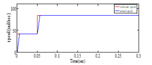
Figure 21: Rotor speed change in the healthy operation
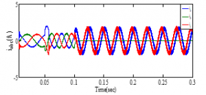
Figure 22: Stator currents in the healthy operation under-speed change

Figure 23: Torque in the healthy operation under-speed change
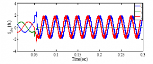
Figure 24: Stator currents under- transient speed change

Figure 25: Torque under transient-speed change
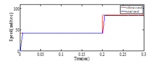
Figure 26: Rotor speed change in the post-fault operation
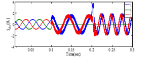
Figure 27: Stator currents in the post-fault operation under speed change
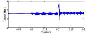
Figure 28: Torque in the post-fault operation under-speed change
7. Conclusion
An integrated fault-tolerant system for open-phase fault in PMSM field-oriented controlled drive has been presented. This drive system consists of a MPCC technique for the fault detection, which is reliable, fast as only a few sampling intervals are sufficient to identify the OPF during steady-state and effectively under transient conditions, together with a fault-tolerant control (FTC) compensation method which utilizes the neutral point to split the single-phase current into two-phase currents that are 60° phase-shifted and equal in magnitude (increased to of the healthy phase current) with minimum hardware. This guarantees the balance in the resultant magneto-motive force allowing for the current vectors regulation returning the operation with almost the same average torque.
The simulation results show the smooth transition from the healthy operation to the post fault operation immediately at the time the fault occurs without loss of machine torque and consequently the speed control. Moreover, the fault detection method is robust enough to discriminate between a real OPF and a normal operation transient condition.
The results obtained under different testing conditions show the robustness and precision of the proposed fault detection and fault compensation methods which makes the proposed integrated fault-tolerant is suitable for PMSM drives used in industrial processes to ensure the reliability of the whole system operation even in the event of OPF.
Conflict of Interest
The authors do declare that there is no conflict of interest.
- F. Betin et al., “Trends in electrical machines control: samples for classical, sensorless, and fault-tolerant techniques,” IEE Ind. Electron. Mag., 8(2), 43–55, 2014, doi:10.1109/MIE.2014.2313752.
- H. Guo, J. Xu, and Y.-H. Chen, “Robust control of fault-tolerant permanent-magnet synchronous motor for aerospace application with guaranteed fault switch process,” IEEE Trans. Ind. Electron., 62(12), 7309–7321, 2015, doi:10.1109/TIE.2015.2453935.
- Y. Wu, B. Jiang, and N. Lu, “A descriptor system approach for estimation of incipient faults with application to high-speed railway traction devices,” IEEE Trans. Syst., Man, Cybern. Syst., 49(10), 2108-2118, 2019, doi: 10.1109/TSMC.2017.2757264.
- W. Wang, J. Zhang, M. Cheng, and S. Li, “Fault-tolerant control of dual three-phase permanent-magnet synchronous machine drives under open-phase faults,” IEEE Transactions on Power Electronics, 32(3), 2052-2063, 2017, doi:10.1109/TPEL.2016.2559498.
- J. Hang, J. Zhang, M. Cheng, and S. Ding, “Detection and discrimination of open-phase fault in permanent magnet synchronous motor drive system,” IEEE Transactions on Power Electronics, 31(7), 4697-4709, 2016, doi:10.1109/TPEL.2015.2479399.
- N. M. A. Freire, J. O. Estima, and A. J. M. Cardoso, “Open-circuit fault diagnosis in PMSG drives for wind turbine applications,” IEEE Trans.Ind. Electron., 60(9), 3957–3967, 2013, doi: 10.1109/TIE.2012.2207655.
- J. O. Estima, N. M. A. Freire, and A. J. M. Cardoso, “Recent Advances in Fault Diagnosis by Park’s Vector Approach,” in Proc. IEEE WEMDCD, 279–288, 2013, doi: 10.1109/WEMDCD.2013.6525187.
- S.-M. Jung, J.-S. Park, H.-W. Kim, K.-Y. Cho, and M.-J. Youn, “An MRAS-based diagnosis of open-circuit fault in PWM voltage-source inverters for PM synchronous motor drive systems,” IEEE Trans. Power Electron., 28(5), 2514–2526, 2013, doi: 10.1109/TPEL.2012.2212916.
- A. Kontarček, P. Bajec, M. Nemec, V. Ambrožič and D. Nedeljković, “Cost-effective three-phase pmsm drive tolerant to open-phase fault,” IEEE Transactions on Industrial Electronics, 62(11), 6708-6718, 2015, doi:10.1109/TIE.2015.2437357.
- L. Wang, Shan Chai, Dae Yoo, Lu Gan and Ki Ng., PID and predictive control of electrical drives and power converters using MATLAB/Simulink, IEEE Wiley, 2015.
- G. Scarcella, G. Scelba, M. Pulvirenti and R. D. Lorenz, “Fault-tolerant capability of deadbeat-direct torque and flux control for three-phase PMSM drives,” IEEE Transactions on Industry Applications, 53, 2017, doi: 10.1109/TIA.2017.2743070.
- X. Zhou, J. Sun, H. Li and X. Song, “High performance three-phase pmsm open-phase fault-tolerant method based on reference frame transformation,” IEEE Transactions on Industrial Electronics, 66(10), 7571-7580, 2019, doi:10.1109/TIE.2018.2877197.
- X. Zhou, S. Li, M. Lu, F. Zeng, M. Zhu and Y. Yu, “New fault tolerance method for open-phase PMSM,” IEEE Access, 7, 146416-146427, 2019, doi:10.1109/ACCESS.2019.2946183.
- A. Akay, P. Lefley and M. Kansara, “Open-Circuit Fault-Tolerant Control for a Five-Phase Permanent Magnet Synchronous Machine Drive,” in 2020 7th International Conference on Electrical and Electronics Engineering (ICEEE), 150-154, 2020, doi:10.1109/ICEEE49618.2020.9102486.
- A. Gaeta, G. Scelba, and A. Consoli, “Modeling and control of three-phase PMSMs under open-phase fault,” IEEE Trans. Ind. Appl., 49(1), 74–83, 2013, doi: 10.1109/TIA.2012.2228614.
- M. Amin, G. A. A. Aziz, M. N. Ibrahim and P. Sergeant, “Open-Phase Fault-Tolerant Current Reconstruction Control of Three-Phase Permanent Magnet Assisted Synchronous Reluctance Motors,” 2019 IEEE Industry Applications Society Annual Meeting, Baltimore, 1-8, 2019, doi: 10.1109/IAS.2019.8912389.
- Ho, Ping-Kwong. An exact model and simulation of a permanent magnet synchronous motor system when driving a light load at low speed, Diss. The Hong Kong Polytechnic University, 2000.
Citations by Dimensions
Citations by PlumX
Google Scholar
Scopus
Crossref Citations
- Aleksander Suti, Gianpietro Di Rito, Roberto Galatolo, "Fault-Tolerant Control of a Three-Phase Permanent Magnet Synchronous Motor for Lightweight UAV Propellers via Central Point Drive." Actuators, vol. 10, no. 10, pp. 253, 2021.
No. of Downloads Per Month
No. of Downloads Per Country