
Multi-Directional Light Sensing Using A Rotating Sensor
Volume 5, Issue 6, Page No 221-227, 2020
Author’s Name: Hoang Anh Dung1,a), Nguyen Manh Cuong2, Nguyen Phan Kien3
View Affiliations
1Faculty of Electronics Technology and Communication, Hanoi Open University, Hanoi, 100000, Vietnam
2Military Technical Academy, Hanoi, 100000, Vietnam
3School of Electronics and Telecommunications, Hanoi University of Science and Technology, Hanoi, 100000, Vietnam
a)Author to whom correspondence should be addressed. E-mail: dungha@hou.edu.vn
Adv. Sci. Technol. Eng. Syst. J. 5(6), 221-227 (2020); ![]() DOI: 10.25046/aj050626
DOI: 10.25046/aj050626
Keywords: Light Intensity Sensors, Smart Sensor, The Internet of Things, Intelligent Lighting Control, Control and Automation

Export Citations
The performance of indoor illumination control in many applications, such as in an intelligent building, relies on the quality of the light sensors. In many cases, the light level is not uniform and depends on the direction of the illumination source. It usually requires multiple sensors set up in different directions to gather the overall light level. We propose a system that can provide multi-directional light sensing data by rotating a single sensor. This approach overcomes the problem of static sensors network by dynamically changing the measuring angular of the light sensor. We present a sensor system prototype using the ESP8266 controller board, BH1750 light sensor, stepper motor, and 3D printed rotation base mechanism. The system can calculate the sensing angle and transmit sensing data to the monitoring unit or Internet of Things platforms for visualization and analysis. The testing results in normal workrooms show that the rotating sensor can measure the light level in different directions and detect the direction of the main illumination source. Even blocking some directions, the sensor still is able to accurately measure and provide sensing information on the remaining directions. Our sensor system is useful in both whole lighting and local lighting control applications.
Received: 31 August 2020, Accepted: 22 October 2020, Published Online: 08 November 2020
1. Introduction
Light sensing information has a vital role in illumination control applications as in industrial lighting or a sensor-actuator (S-A) building. The characteristics and capability of light sensors highly affect lighting control performance. The indoor illuminance depends on both artificial and natural light. The light measuring is not just based on the photodetector in the sensor, but also other factors like sensor direction and occupant activities. Typically, the S-A system uses multiple light sensors or a network of sensors that are located distributively. As mentioned in [1], there are challenges in the use of a network that contained a large number of sensors such as unreliable sensor nodes (fault tolerance), difficult to add a new sensor or to change sensors direction (scalability), and late respond of light changing events (low latency). For a single sensing node, the sensor could be blocked by unaware objects or illuminated by an offensive light beam (not the lighting source), causing an inaccurate measurement. We proposed in [1] a rotating light sensor system that helps to reduce these issues. This paper presents a new design of the system with more details of the evaluation results.
The system proposed in [1] used a single light sensor rather than multiple sensors, and the sensor can rotate freely to measure the light illuminance from numerous directions. The sensor also recognizes the measuring angle as a part of the sensing data. In [1], we introduced a demonstration version of the sensor system that had a relatively large size. We present here a new version with a reduction in the overall size. For validation purposes, we add a static sensor to the system. The significant advantage of our system is that it is able to provide light sensing data at different angles using just a single sensor compared to a system that uses multiple sensors. The rotating sensor can detect the temporary light changing at a specific angle or determine which measuring direction may have been blocked. These features allow the sensor to accurately tracking the light information in real indoor applications. The system can also work on the Internet of Things (IoT) [2] applications since it can connect and transfer data to the popular IoT platforms.
The paper is organized as follows. The following section provides the related works. The methodology, design, and features of the rotating sensor system are presented in Section 3. The performance analysis and experimental results are provided in Section 4. The last section concludes the paper.
2. Related Work
Light sensing data is used in the illumination control system is often come from either a single sensor or a network of sensors. The use of light sensors networks has become more popular, especially in medium and larger size applications. Using a single sensor may not provide enough sensing information, while a network of sensors has the challenges of fault tolerance [3], scalability [4], and low latency [5]. We have observations about these challenges based on our work in light sensing and lighting control research. Firstly, the fault tolerance feature in the light sensors network requires the system to work correctly when some sensors may have been failed. It is difficult to satisfy this requirement when the light sensors are distributed at a different location. For the scalability, there is a challenge in the application that requires to increase illumination areas such as in the commercial center or industrial working floors. In such a case, the component cost would increase, and the sensor system should be portable enough to adapt to the extensions. Lastly, the static sensor system may have a low latency issue system when it places the sensor in a fixed direction and orientation. The static system may not quickly sense the changing of illumination level in the zones uncovered by the sensor. In [6], the lighting control system used the wireless sensor networks data to control the illumination to reduce the energy costs. A significant deployment and maintenance costs of the sensors was reported. In addition to the components cost, there was another complexity in the controlling system related to the variation of the light level caused by the sunlight [6]. The study in [7] indicated the effect of other natural factors like sun movement, clouds, and shadows on changing the light levels in the testing applications. The effect of distance and direction of the sensors and light sources on the sensing data was studied in [8]. They studied the controlling of both overall and local illumination. The controlling plan uses the local light sensing data to provide illumination upon the user’s needs. A limitation is that the system requires a light sensor to be carried with the user to measure the local light level. These local measurement data were used in the illumination controlling plan to meet the user requirement.
For the location-based illumination control, the whole lighting provides background light, and the local lighting provides concentration light [9]. In this system, the control system uses light sensing data to control both background and concentration illumination. The work in [10] had evaluated the effect of the local light sensing on controlling the whole lighting devices. It also requires to determine the location zone of the user to provide the personalized light control [11, 12].
In [13], the author studied the distributed light control system to accommodate both the user occupancy and the natural daylight level. A large number of light sensors were used in their system to examine the relationship between the occupation bases and the relevant light sensors. The testing result also indicates the dependence of the light control performance on the accuracy of the local and whole light sensing information.
We have not seen such a system using a rotating sensor in light sensing applications. In the field of radio tomography, a study presented in [14] introduced a rotating RF sensor system to sense the radio system from multiple directions and improve the accuracy of tomographic imaging. As we stated in [1], since the light ambient is heterogeneous, it is necessary to create a light sensor system that can measure light from different angles and reduce the problem of multiple sensor networks. Such a system is useful to increase the quality of intelligent lighting control applications.
3. Design of the new Sensor System
The rotating sensor motioned in [1] was a demo prototype. We have designed a new version of the sensor system that could be used as a real measurement tool. An image of the new sensor system is presented in Figure 1. The new design took care of the following factors:
- Improving the rotation system.
- Reduce the distance between the sensor and the rotation module.
- Optimizing the overall diameter of the sensing system.
- Adding a static sensor for referencing.
3.1. Multi-Directional Light Measurement Vector
Consider a visible light source s, the Lumens from this source can be calculated based on the Is intensity [15] as:
![]()
For the isotopic light source, where the intensity is the same in all directions, the measurement of the luminous flux on a unit area, also known as or light level in a specific area or illuminance, is the ratio of the Lumens Φ over the area of the measuring surface. However, in the indoor environment where the source is not isotopic, for a flat radiating surface of a sensor, the calculation of the illuminance need to consider cosine the observation angle (θ) with respect to the surface normal as shown in the Equation (2)
![]()
In the lighting control system, the observed ∆E, changing of illuminance on the light sensor surface, are used to control light bulb brightness:

EN−1
where N is the number of the measuring directions and En is the measured illuminance at the direction n ∈ [0, N − 1].
There are two major advantages of the sensing data provided by a rotating light sensor comparing to a static sensor. First, the light intensity measured by a static sensor depends on a single sensing direction, the angle θ as in Equations (2) and (3), while the rotating sensor provides a combination of illuminances from multiple directions. In the real application, such as lighting control, the measuring direction could be blocked by an object that makes the sensing value of the static sensor inaccurate. The rotating sensor can be able to void this issue as it measures the light from different angles. Second, the rotating sensor uses a vector of illuminance (4) that can indicate the main light source direction. Furthermore, we can apply the gradient calculation (∇) on the vector of illuminance to measure the rate and direction of change in the light intensity.
3.2. Features of the Rotating Sensor System
The new sensor system is shown in Figure 1 has an overall diameter of 100 mm. This design is small enough to use in most indoor applications. Table 1 summarizes the features of the sensor system. The system uses one light sensor to dynamically measure multidirectional light intensity. In this system, there is no need to use many sensors as in a sensor network. By rotating the light sensor, our system may avoid the issues when the static measuring angle has been blocked by an object.

Figure 1: A sample image of the new rotating light sensor system. The light sensor is attached to the side of the curved handle of the rotation base structure.
Table 1: Features of the sensor system
| System Features | Value |
| Light Sensor | BH1750 |
| Stepper Motor | 28BYJ-48 |
| Stepper Motor driver board | ULN2003 |
| Microcontroller Module | ESP8266 |
| Overall Dimension (mm) | 100 |
| No. of Measuring Directions | 8 and 16 |
| Sensor Measuring Resolution (Lux) | 1 (high) or 4 (low) |

Figure 2: Diagram of the sensor system.
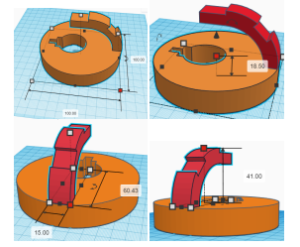
Figure 3: Sample views of the rotation base structure design.
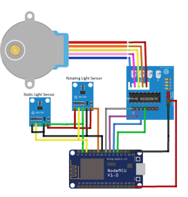
Figure 4: Conceptual logic circuit of the sensor system.
As shown in the system diagram in Figure 2, the major components of the system are the light sensor, stepper motor, motor diver board, and the main control board. The system uses a microcontroller to control the rotation, sensing the light illuminance, and transfer data to the monitoring platform. In this design, we have improved the rotation system and created a new base structure of the sensor. Figure 3 shows several views our the new base structure.
The structure was 3D printed and used in the sensor system.
As a modified version in [1], the new system uses an additional static sensor to provide a reference as requested. In this study, we consider the static sensor is the sensor that has a fixed sensing surface normal vector, thus the observation angle θ for any lighting source stays unchanged (see Equation 2). The rotating sensor is the sensor that its observation angle can be changed. By rotating the sensor in an axis different than the normal vector of its sensing surface, we can change its observation angle.
The logic circuit of the new system is shown in Figure 4. The sensors communicate with the microcontroller using the I2C protocol. Both static and rotating sensors are the BH1750 [16] digital light intensity measuring module. The sensor module has an internal converter to convert the analog signal to the digital value. The module also contains a preprocessor to process the digital value and return the measuring value in the range of 1 to 65535 Lux.
The circuit uses a ULN2003 stepper motor driver to provide a drive interface between the microcontroller and the stepper motor. The ULN2003 driver pins, IN1, IN2, IN3, and IN4, are connected to the microcontroller digital pins. The power supply pins (VCC and GND) of the ULN2003 driver board are connected to the microcontroller 5V pin and GND pin, respectively. The stepper motor, model 28BYJ-48, runs in 32 steps mode and has a built-in gear with a 64 to 1 reduction ratio to produce 2048 steps per revolution. The step-angle relation is calculated as:
where α represents the angle, and i is the number of controlling step of the motor. Sample images of the motor and the driver board were presented in [1]. In this new design, the motor is attracted to the center hole of the base structure shown in Figure 3. The motor can rotate the whole structure hence rotate the light sensor. For the microcontroller, we used the ESP8266 [17] board that runs in the Arduino environment. This module has a Wi-Fi microchip with a full TCP/IP stack to transfer the data. We program the system in the Arduino code using the C++ programming language.
Table 2: Relation of the sensing directions, angle interval, and motor steps interval
| No. of Sensing Directions | ∆α | Steps Interval |
| 8 | 45◦ | 256 |
| 16 | 22.5◦ | 128 |
| 32 | 11.25◦ | 64 |
| 64 | 5.625◦ | 32 |
3.3. Measuring Multi-Directional Light Illuminance
The main procedures of the illuminance measurement are kept similar to in [1] except for the additional signal of gathering the static sensor data. As mention in [1], for the applications that require the data of light intensity in different directions, the users may have to manually set up several sensors at different orientations. We developed an algorithm to automatically rotate the sensors, calculate the angles, and gather the illuminance in multiple directions. Figure 5 presents the major steps of the algorithms. In the beginning, the program set up the initial direction of the sensor. The sensor can rotate in a full 360◦ revolution, hence any angle can be set as the initial sensing direction. Then the sensor system starts collecting the angle and illuminate data. In each iteration of the major loop shown in Figure 5, the control program rotates the sensor by increasing the motor step, calculates the sensing angle, gets the light level information, and transmits the data to the monitoring software. The counting of the motor steps is used to calculate the angle based on the Equation (5). When the motor reaches a full circle (at 2048 counted steps), the counting is reset to Zero, and the rotating direction is reversed. The sensor system can measure light in any direction or at a group of interval directions. Table 2 summarizes some combinations of the sensing directions, angle interval (∆α), and the motor steps interval. The visualizations of 8 sensing directions with 45◦ apart and 16 directions with 22.5◦ apart are shown in Figure 6.

Figure 5: Flowchart of the control algorithm of the light sensor system. The major procedures are to control the rotating light sensor. The command to get static light sensor data is optional.

Figure 6: Sample views of the rotating light sensor with different number sensing angles. Left: 8 directions from d0 to d7 with ∆α = 45◦. Right: 16 directions from d0 to d15 with ∆α = 22.5◦. The lights are for presentation purpose only.
4. Performance Analysis of the Sensor System

Figure 7: Snapshot of monitoring the light sensing data on the Ubidots website.
Indoor lighting control is the major application of our proposed sensor system. We have tested the system in a workroom with the effect of the popular parameters on the sensor, like the changing of light power and blocking object. We present here the experiments and results for testing the ability of the system to detect the main light direction, detect the blocked direction, and accurately measure light intensity.
4.1. Measuring and Transmitting Light Data
In [1], we presented the experiment that showed how the sensor measures the light level from multiple directions. For this new design, in addition to the multi-directional light sensing data, the system also collects the sensing data of a static reference sensor. We tested our device on transferring the data to the Ubidots [18] IoT platform. The data was transferred remotely through the Wifi signal. Figure 7 shows a part of the testing data monitored on the Ubidots website with multiple light sensing signals in one plot. We also have tested our system with the ThingSpeak [19] platform that has integrated MATLAB toolbox for analyzing the data.
For the data presented in Figure 7, the rotating sensor measured the light in 16 directions with ∆α = 22.5◦ (Table 2 contains more detail of the measuring angles). It can be seen that our system is able to measure and provide light sensing data from multi-directional. In Figure 7, the rotating sensing data is labeled as a topic channel for each direction from topic0 to topic15. The static sensor channel is labeled as topic16. When monitoring the data, the channel topics (directions), the Lux values, and the measuring times can interactively be seen by selecting a data point on the graph. As shown in the figure, different sensing direction has a different value. In the beginning, when all lights were off, all sensing data was low (roughly under 150 Lux). Then, after we turned on all the lights (around 11:55 am timestamp, see Figure 7), the system recorded the increase of light levels in all directions. We blocked some directions of the rotating sensor at two later movements. As of the result, there were two failings of the light level at the blocked directions (in the 12:05 – 12:10 pm and the 12:25-12:30 pm periods, see Figure 7). In this experiment, the static sensor (topic16) was not blocked at any time, and it was used to provide the reference sensing data.
4.2. Detecting Main Light Direction
The distribution of light sources may generate an unbalance light level in the room. Our sensor can detect the major light direction that information helps to rearrange the illumination sources or indicate the location having the best light level. In this experiment, we place the rotating sensor at the center of a workroom that has several light sources. The light sources were placed around the room at different locations and distances to the sensor. We regularly turn on the lights to test the sensor performance. The sensor was set to measure in 16 directions (d0…d15, with ∆α = 22.5◦). Figure 8 displays some radar charts of the measured results. For each chart, the data value as a length on angular spokes represents the magnitude of sensing value in a corresponding direction. The line connects the data values represses one full rotating revolution (360◦).

Figure 8: Radar charts of light sensing data on different main illumination directions.
The charts in Figure 8 associate with four scenarios of the lighting in the testing room. For an instant, Figure 8 (a) shows the Lux values measured in directions d2 , d3, and d4 are much higher than the rest. In that case, only the light source at the direction of d3 was on, hence there is a peak sensing data in d3 (about 250 Lux) and two relevant highs on the adjacent angles d2 and d4. Figure 8 (b) shows the major level of light in d5, d6, and d7 with the peak value of 350 Lux, and Figure 8 (c) shows the main level in d12, d13 and d14 with above 500 Lux peak value. These results plotted in the radar charts admit that the rotating sensor can detect the direction of the main light source. This result also can be observed from our vector of the illuminance shown in Equation 4 since the direction of the vector is influenced by the major scalar member values. Figure 8 (d) presented a test case where the light level is more consistent on the left side of the sensor (d9 to d15). In the case of a uniform light level, we may obtain consistent light sensing values in all directions.
4.3. Detecting Blocked Directions
We have performed an experiment to show how the rotating sensor can detect the temporary blocking directions with sudden changes in the sensing data. During this test, the rotating sensor was set up to run first, and then some sensing directions were temporarily blocked. Figure 9 plots the testing result. Before the time T1, the sensor indicates the major light level in directions d4, d5, d6, d7 and d8 with the high value above 300 Lux (d6). In the period of T1 and T2, when the sensor was blocked from the major light source direction, there was a sudden fall in the sensing value of the relevant angles. As plotted in Figure 9, all sensing values of d4 to d8 directions have steeply decreased to around 50 Lux while other values mostly unchanged. After the T2 moment, when the blocking object moved out, the sensing values from the main light directions got back to normal. It can be seen that we can use the directions having a temporary steeply reduction to indicate which sensing angle of the sensor was blocked. In the experiment presented in [1], we reported the result of detecting a sudden change of the natural background light, such as when opening the doors to get more sunlight.
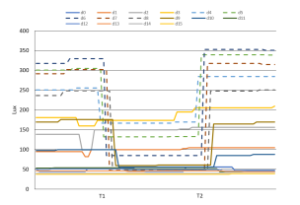
Figure 9: Sensing data of the rotating sensor when blocking some sensing angles.
4.4. Accuracy Analysis
The demand level of illumination to be controlled depends on the change in the sensing value. When using a single sensor or a network of sensors that was set at a static direction, it is possible that an unaware object temporarily blocks the sensor. Such a case makes a temporary change in the measuring data, leading to an inaccurate controlling of the illumination. The rotating sensor provides light sensing values from different directions that can help to avoid this problem.
We performed an experiment that used both static and rotating sensor. The artificial lighting sources were kept unchanged, but the static sensor would be blocked at a certain time during the experiment. Figure 10 shows the LUX values of the static sensor at a fixed angle and the rotating sensor rotated in eight directions (from d0 to d7 ). In this experiment, the rotating sensor measures light at every 45◦. In the beginning, the static sensor data was around 450 Lux (±20), while the rotating sensor had different values at different directions with the high value in d4 of above 500 Lux and d3 around 430 lux. The directions d0, d5, and d7 had sensing values in between 320 and 350 Lux, and the direction d1, d2, and d6 had data in the range of 270 to 300 Lux. Then, we blocked the measuring direction of the static sensor. As shown in Figure 10, there is a sharp fall in the value of the static light sensing data down to 100 Lux and lower. If an application used just the static sensor to control the lights, it would incorrectly record a reduction in the light level and would control an unnecessarily increase of the illumination power. There was no need to change the illumination since the lights were stable throughout this experiment (except for a small variance in the natural light). For the rotating sensor, the sensing signals in the directions d0, d1, d6, and d7 were almost stable (around 300 Lux and 350 Lux). There was a small reduction in the direction d2 and d5 and a quire decreasing in the direction d3 and d4, but these sensing values were still around 250 Lux. When we blocked the static sensor, we approached the sensor location through the direction d3 and d4 that caused the changing of the data in these (and surrounding) directions. If we use the rotating sensing data of multiple directions for the lighting application, the control unit could use the data of the stable directions and decide to keep the illumination level the same. The prevention of an unnecessary increase in illumination power is useful to save energy costs.

Figure 10: Light sensing values of the static sensor and the rotating sensor. The static sensor was blocked at a certain time, causing a reduction in the sensing value. The time ticks in the horizontal exist are presented at 60 seconds interval.
5. Conclusion
We have presented a rotating light sensor system that can measure light level in multi-direction rather than using server sensors positioning at different orientations. The system uses a stepper motor to rotate the sensor and track the motor steps to calculate the measuring angle. The light level values can be directly transferred to the moni- toring system for further process. Besides, the sensor can connect with the popular IoT platforms, such as Ubidots and Thingspeak, to remotely visualize and analyze the sensing data. We also presented a new design of the sensor system with an optimal compact structure. The performance of the sensor system has been evaluated through testing experiments. The results show that the proposed sensor system is able to measure light level in different directions, detect the main light source direction, and determine the directions having temporary light changing. Moreover, even some sensing directions may be blocked, the rotating sensor still accurately measures the light level in other directions. In the future, we intend to develop a three-dimensional (3D) rotation light sensor. A motion tracking sensor shall be used to keep track of the 3D orientation. We plan to optimize the rotation system and perform more experiments of using the rotating light sensor in the light control applications.
- D. A. Hoang, T. T. Tung, C. M. Nguyen, K. P. Nguyen, “Rotating Sensor for Multi-Direction Light Intensity Measurement,” in 2019 International Con- ference on System Science and Engineering (ICSSE), 462–467, 2019, doi: 10.1109/ICSSE.2019.8823447.
- A. P. Plageras, K. E. Psannis, C. Stergiou, H. Wang, B. B. Gupta, “Effi- cient IoT-based sensor BIG Data collection–processing and analysis in smart buildings,” Future Generation Computer Systems, 82, 349–357, 2018, doi: https://doi.org/10.1016/j.future.2017.09.082.
- S. Chouikhi, I. El Korbi, Y. Ghamri-Doudane, L. A. Saidane, “A survey on fault tolerance in small and large scale wireless sensor networks,” Computer Commu- nications, 69, 22–37, 2015, doi:https://doi.org/10.1016/j.comcom.2015.05.007.
- C. Dandelski, B. Wenning, D. V. Perez, D. Pesch, J. M. g. Linnartz, “Scalability of dense wireless lighting control networks,” IEEE Communications Magazine, 53(1), 157–165, 2015, doi:10.1109/MCOM.2015.7010529.
- I. Parvez, A. Rahmati, I. Guvenc, A. I. Sarwat, H. Dai, “A survey on low latency towards 5G: RAN, core network and caching solutions,” IEEE Commu- nications Surveys & Tutorials, 20(4), 3098–3130, 2018, doi:10.1109/COMST. 2018.2841349.
- V. Singhvi, A. Krause, C. Guestrin, J. H. Garrett Jr, H. S. Matthews, “Intelligent light control using sensor networks,” in Proceedings of the 3rd international
conference on Embedded networked sensor systems, 218–229, ACM, 2005, doi:https://doi.org/10.1145/1098918.1098942. - J. Lu, D. Birru, K. Whitehouse, “Using Simple Light Sensors to Achieve Smart Daylight Harvesting,” in Proceedings of the 2Nd ACM Workshop on Embed- ded Sensing Systems for Energy-Efficiency in Building, BuildSys ’10, 73–78, ACM, New York, NY, USA, 2010, doi:10.1145/1878431.1878448.
- L. Yeh, C. Lu, C. Kou, Y. Tseng, C. Yi, “Autonomous Light Control by Wire- less Sensor and Actuator Networks,” IEEE Sensors Journal, 10(6), 1029–1041, 2010, doi:10.1109/JSEN.2010.2042442.
- M. Pan, L. Yeh, Y. Chen, Y. Lin, Y. Tseng, “A WSN-Based Intelligent Light Control System Considering User Activities and Profiles,” IEEE Sensors Jour- nal, 8(10), 1710–1721, 2008, doi:10.1109/JSEN.2008.2004294.
- D. Caicedo, A. Pandharipande, “Distributed Illumination Control With Local Sensing and Actuation in Networked Lighting Systems,” IEEE Sensors Journal, 13(3), 1092–1104, 2013, doi:10.1109/JSEN.2012.2228850.
- K. Warmerdam, A. Pandharipande, “Location data analytics in wireless lighting systems,” IEEE Sensors Journal, 16(8), 2683–2690, 2015, doi: 10.1109/JSEN.2015.2509982.
- X. He, A. Pandharipande, “Location-Based Illumination Control Access in Wireless Lighting Systems,” IEEE Sensors Journal, 15(10), 5954–5961, 2015, doi:10.1109/JSEN.2015.2449276.
- N. van de Meugheuvel, A. Pandharipande, D. Caicedo, P. van den Hof, “Dis- tributed lighting control with daylight and occupancy adaptation,” Energy and Buildings, 75, 321 – 329, 2014, doi:https://doi.org/10.1016/j.enbuild.2014.02. 016.
- M. Bocca, A. Luong, N. Patwari, T. Schmid, “Dial it in: Rotating RF sensors to enhance radio tomography,” in 2014 Eleventh Annual IEEE International Conference on Sensing, Communication, and Networking (SECON), 600–608, 2014, doi:10.1109/SAHCN.2014.6990400.
- C. Nave, “Hyperphysics,” 2020.
- M. electronics, “BH1750 ROHM Semiconductor Datasheet,” 2020.
- E. Systems, “ESP8266 Overview,” 2020.
- Ubidots, “Ubidots Internet of Things and Cloud tools,” 2020.
- thingspeak, “ThingSpeak IoT analytics platform,” 2020.