FPGA-Based Homogeneous and Heterogeneous Digital Quantum Coprocessors

Adv. Sci. Technol. Eng. Syst. J. 5(6), 1643–1650 (2020);
 DOI: 10.25046/aj0506195
Quantum computers are heterogeneous device. It consists of a main CPU and a quantum accelerator. True quantum accelerator (or coprocessor) is analog and probabilistic device. Qubits are the basic building blocks of quantum computers. But qubits can be digital. A digital qubit is similar to RISC processor pipeline and is an unique chain of digital gates. In this work, it is proposed to execute quantum routines in quantum computer not on the quantum chip but on the chip of a digital FPGA. This paper presents the architecture of such FPGA – an architecture of digital quantum coprocessor. The paper presents two types of digital quantum coprocessors – heterogeneous and homogeneous. The advantage of a homogeneous coprocessor is shown. The IP Core generator was developed to create VHDL descriptions of digital quantum elements and digital quantum coprocessors in general. In this paper heterogeneous quantum computer which consists of a main CPU and a FPGA-based quantum accelerator (coprocessor) has been proposed. And these FPGA-based digital quantum coprocessors can have a homogenous or heterogeneous structure. Quantum coprocessors have up to 1024 qubits in one FPGA. A homogeneous quantum coprocessor performs better than a heterogeneous one. Also, its implementation is easier. The measured ratio of correct results for a 1024-qubit homogenous coprocessors is more then 50 %.
1. Introduction
This paper is an extension of work originally presented in IEEE 11th International Conference on Dependable Systems, Services and Technologies (DESSERT) [1].
Quantum algorithms are a mixture of classical logic and quantum routines which can be executed on the quantum chip. In [2] a heterogeneous quantum computer architecture was presented. According to [2] a quantum computer consists of both a classical and quantum computing part.
In this work, it is proposed to execute quantum routines in quantum computer not on the quantum chip but on the chip of a digital field programmable gate array, on a FPGA. This paper presents the architecture of such FPGA – an architecture of digital quantum coprocessor.
As an extension of the results described in [1] heterogeneous and homogeneous digital quantum coprocessors are considered. It is important to note that a heterogeneous quantum computer and proposed heterogeneous quantum coprocessor are completely different concepts.
Also, the number of digital qubits in the coprocessors under study was increased to 1024.
Von Neumann architecture had for a long time a single processor. Then homogeneous multi-core processor dominated the processor development. In the era of microprocessors, the understanding came that heterogeneity is the best way forward to improve the compute power. System architecture with heterogeneous accelerators includes the main CPU and heterogeneous coprocessors such as floating-point math coprocessors, graphics and neural accelerators, FPGAs. In [2] and [3] heterogeneous quantum computer which consists of a main CPU and a quantum accelerator has been proposed. In this paper heterogeneous quantum computer which consists of a main CPU and a FPGA-based quantum accelerator (coprocessor) has been proposed. And these FPGA-based digital quantum coprocessors can have a homogenous or heterogeneous structure and can be used at the lowest level of full-stack quantum accelerators along with quantum chips and quantum simulators [3].
A quantum computer contains N qubits and a digital quantum coprocessor contains N digital qubits. In both cases as a result of any calculations they can produce any of 2N results. But the same calculations can lead to different results. And every i-th result will be produced with probability pi.
A qubit can be thought of as a device that has a group of inputs for data and instructions that control its behavior. Unlike a real qubit, a digital qubit can have an additional group of outputs. The exact qubit state code is generated on this group of outputs. An important element of the digital qubit is a pseudo random number generator (PRNG). Together with the qubit state code, the pseudo-random code is used to generate a probabilistic result at the one-bit output of the qubit (Figure 1) [4].
Quantum volume VQ is a metric that measures the performance of a quantum computer’s capabilities and error rates [5]. In the simplest case, the quantum volume is d·N. Now the quantum volume of a real quantum computers is very small (at the level of milliseconds), but for digital quantum coprocessors it is practically unlimited.

Figure 1: Digital qubit symbol
The DiVincenzo [6] criteria are conditions necessary for constructing quantum computer. Not a single word about the physical nature of a quantum computer is included in this criterion. Therefore, you can try to create digital quantum computer. It can be created either as a software model or as a hardware device.
“You can run a simulator on your phone that can run a 20-qubit system. But once you get up close to 50, the amount of memory you need to run a simulator gets into the petabytes [of memory]. Over 50 and there is no way you can pretend to be a quantum computer. At that point you really need a true quantum computer” [7].
The number of qubits required for solving practical problems is now estimated at several thousand [8]. Creating a true quantum computer with so many qubits is a very difficult task, and a digital quantum coprocessor can already be created on one FPGA.
The purpose of the article is to demonstrate the advantages of digital quantum computers over true ones. For this, it is necessary to develop a circuit for a digital qubit and a digital quantum coprocessor as part of a digital quantum computer. To compare different coprocessors, it is necessary to develop methods for their comparison. In this works digital quantum computers with 2n qubits (n = 5, 6, …, 10) have been used for research.
Also, the purpose of the work is to determine the timing and hardware characteristics of the developed digital quantum coprocessors.
An important task is the problem of the reliability of the results of modeling the operation of digital quantum coprocessors. In this work, it was successfully solved, it was shown that simulation results coincide with the results obtained during prototyping.
2. Theoretical Foundations of Quantum Computing
At any moment a classic computer can be exactly in one of the states and a quantum computer is simultaneously in all these basic states, in a state of quantum superposition, which is described by a wave function. But during the measurement, the quantum state turns into one of the basic states with a probability pj.
Along with measurement, the quantum superposition can be changed under external influence.
The quantum state is described by a wave function , , [9].
In the simplest case of a single qubit, its wave function change is illustrated by the movement of a single vector [9] either in the Bloch sphere (for complex amplitudes of wave function, [10], [11]) or in a circle (for real amplitudes, [4], [12], [13]). In unit circle for one qubit and respectively.

Figure 2: A Bloch sphere (left) and a unit circle (right)
A true quantum computer is an analog device and it has no memory. It has only gates. Therefore, there are no quantum programs. In the drawing of a true analog quantum computer, a sequence of quantum gates shows only the time sequence of qubit state changes. Software tool [14] allows to create circuits from quantum gates, simulate their work and manage it with C-like language instructions. This is very similar to the FPGA design.
In the schema of a digital quantum computer, a sequence of digital quantum gates shows both the time sequence of qubit state changes and the relative physical position of the gates themselves in the space.
A good illustration of a qubit can be an electron spin. An electron can change its spin in time from 1 to 20 nanoseconds [15]. This time can serve as a base operation time for compare the performance of true and digital quantum coprocessors.
To compare the capabilities of true and digital quantum computers, one can calculate the quantum volume as a metric that measures the performance of a quantum computer’s capabilities and probability that the qubit will work for some time t without failure:
QV = N*p(t),
p(t) = e-t/MTBF is probability that the qubit will work for some time t without failure where (MTBF – Mean Time Between Failures);
N is qubits number.
For true qubits MTBF is microseconds and millisecond and p(t) run to 0 when t > 1 ms, QV << N.
For digital qubits MTBF is practically unlimited (MTBF of modern FPGA is at level 50 years) and p(t) run to 1. So, for digital quantum coprocessor QV = N.
The results of comparison of analog data processing methods, which are used in true quantum computers, and digital methods are summarized in the Table 1. All this speaks about the prospects of creating hardware digital quantum computers.
3. The Structure of FPGA-based Digital Quantum Coprocessor
A classical computer controls the operation of a quantum coprocessor (Figure 3) provides it with an input data, instructions and checks the result of its work [4]. This interaction is well described as a full-stack of the layers of an accelerator at [3].
A generalized functional diagram of full-stack hardware resources of quantum computer with realized in FPGA quantum coprocessor is given in Figure 4 [4].
Table 1: Comparison of analog and digital data processing methods
| Characteristic | Analog processing methods | Digital processing methods |
| Speed | + | – |
| Versatility | – | + |
| Microminiaturization | – | + |
| Accuracy | – | + |
| Zoom | – | + |
| Transmission in space | – | + |
| Transmission in time (memory) | – | + |
| Immunity | – | + |
| Reliability | – | + |
| Testing, debugging, diagnostics | – | + |
| Quantum volume | – | + |
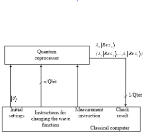
Figure 3: A classical computer with quantum coprocessor.

Figure 4: A digital quantum coprocessor for classical computer.
The top-level functionality of this stack is provided by the classic host computer. Functioning at the microarchitecture level is provided by embedded in FPGA microprocessor (AWP, control unit).
And directly quantum computing is provided by a set of digital qubits and a switch matrix which connects the qubits to each other and transmits the final state code of all of them or only those required at the moment to the control unit.
The connections between qubits can be static or dynamic. In this work static connections have been used. They do not change while the computer is running.
A digital qubit consists of j series-connected digital quantum cells (Figure 5).
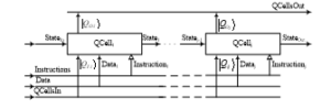
Figure 5: RISC processor-like structure of a digital qubit DQBit.
Such a connection is similar to the connection of stages in a RISС processor. Every digital quantum cell performs a single operation that changes the state code of a qubit and its measured state . The state code Statej changed in one quantum cell is transmitted to the input of the next cell. The first cell in the chain receives an initial state code from a control unit. The state code of the last cell is the resulting qubit state code. Each cell receives instructions and data from the coprocessor control unit. It also receives the measured states of other qubits from the coprocessor switch matrix.
Each digital quantum cell includes a digital quantum gate, a state measurement unit, a pipeline register (Figure 6) and inverse functional transformer in the output of PRNG. PRNG provides the formation of probabilistic results of the qubit operations.

Figure 6: A digital quantum cell QCell.
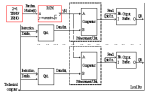
Figure 7: Homogenous quantum coprocessor
A digital quantum gate transforms the input qubit state code into the output code under the influence of the instructions and their data, as well as under the influence of measured states of another qubits.
Inverse functional transformation allows the creation and research of two types of digital quantum coprocessors:
each quantum cell of the heterogeneous coprocessor has its own pseudo-random number generator and its own functional transformer;
a homogeneous coprocessor contains only one pseudo-random number generator and only one functional transformer for all quantum cells, for all quantum qubits (Figure 7).
A simplified topology of a part of a FPGA chip with resources available to the user for design is shown in the Figure 8. These resources are sets of configurable logic blocks CLB, programmable switching machines PSW and I/O blocks IOB. The PSM and the wires laid on the chip between them and CLB make it possible to connect the CLB to each other. CLB can be programmed to act as a qubit (QB) or quantum cell (QC). This allows many digital qubits to be placed on one chip. The interaction of qubits and the control of qubits is carried out by digital methods using PSM. The use of COTS FPGAs makes it possible to create digital quantum coprocessors with a large number of qubits, which can operate for a long time under normal conditions.

Figure 8: Simplified topology of digital quantum coprocessor FPGA chip
Recently, other developers have also tried to connect digital technologies with true quantum computers:
place true qubits on the crystal (similar to the Figure 8 shown) and organize interaction between them using digital methods [16]. It uses a custom crystal that can operate at ultra-low temperatures (near 4° K);
carry out optical control of true qubits embedded in the chip [17];
use a pseudo-random number generator in true quantum computers [18].
In this study digital quantum coprocessors were implemented for the case of wave function real amplitudes (Figure 2) and for polar coordinate system to represent the movement of the vector (Figure 13) [12].
Algorithm design steps for digital quantum computer design on FPGA are standard for FPGA design:
to create or to find an algorithm for solving the problem;
to find or to create a mathematical description of the solution to the problem;
for FPGA-based circuits to create graphic symbols of library elements and their descriptions in hardware description language;
- to create a schema from library elements;
- to simulate the created schema;
- to implement the project;
- to verify the project;
- to make a prototype project.
The IP Core generator was developed to create VHDL descriptions of digital quantum elements and schema of digital quantum coprocessors in general.
4. Testing Digital Quantum Coprocessors
The quantum Fourier transform (QFT) as a part of Shor’s algorithm [19] (Figure 9) for factorization [11] was chosen to compare different variants of quantum coprocessors.
The QFT is defined as
 ,
,
When implementing a digital qubit in the form of a chain of digital quantum gates and implementing only a QFT circuit on FPGA, there is no need to change the functions of the quantum gates. Therefore, the functions of each gate are determined only by their circuit. And there is no need for instructions that change the function of the gates. Therefore, they are not shown in the Figure 12, but are shown in the general diagram Figure 4. And the data path in the Figure 12 is a chain of links named Q*, along which the changing qubit state code goes from one gate to another. The measured states of a qubit, which are called q*, are transferred from one gate to another as required by the algorithm for solving the problem. QFT determines spectrum of qubits states.

Figure 9: Quantum factorization by Shor’s algorithm

Figure 10: QFT drawing

Figure 11: Simplified drawing of QFT (5-qubits)
The diagram for FPGAs corresponding to the Figure 11 is shown in the Figure 12.
The QFT results were obtained as described in [12] and [13].
5. Simulation and Verification of FPGA-based Digital Quantum Coprocessor

Figure 12: FPGA schema of QFT (4-qubits)
For analysis the input state of qubits, which can conditionally be described as |XXX..X0>, where X corresponds to the neutral position of the vector in the unit circle – at angle of π/4, was selected. The probability of measuring the input state with odd code is podd=0, and with even codes is peven = 100/2n-1 %, where n is qubits quantity and the spectrum of qubit states at the QFT input will look like in Figure 14 (for 4 qubits).
QFT simulation results for this case are shown in Figure 15. The 4 qubit digital quantum coprocessor determines the period of the input states spectrum with probability 38,5 %, so it correctly executes a QFT.
Also digital quantum coprocessors with up to 1024 qubits, have been investigated [13], [20]. Similar studies were performed for other periods in input states spectrum (for 0, 1, 2, 4, …, 2n-1 periods) [13].
Implementation results are summarized in Table 2.
Table 2: Implementation Results of Heterogonous Digital Quantum Co-Processors (2n-1 periods)
| Qubit number, n | CLK period (ns) | LUT
number |
RAM
number |
FPGA resoirces, % R | FPGA 7z type
[21]. |
| 128 | 2.353 | 32352 | 14 | 045 | |
| 64 | 4.289 | 16043 | 15 | 010 | |
| 32 | 3.874 | 7983 | 010 | ||
| 16 | 3.606 | 4000 | 010 | ||
| 10 | 3.976 | 2522 | 010 | ||
| 10 | 4.180 | 4307 | 24 | 010 | |
| 10 | 5.137 | 3754 | 010 | ||
| 10 | 5.281 | 3650 | 20 | 16 | 010 |
32-qubit digital quantum coprocessor (Figure 18) was implemented on ZedBoard Zynq-7000 ARM_FPGA SoC Development Board (Digilent, Figure 17) for verification.
Verification and simulation results are almost the same (Table 3). This indicates the creation of both a high-quality model of a digital quantum coprocessor and its prototype, which can be used in further research. Each experiment was repeated 4000 times to determine the probability of getting the correct result (Figure 19). The average level of correct results during the verification of a heterogeneous coprocessor is 9%, during the simulation of a homogeneous processor is 61%, during the verification of a homogeneous processor is 58%.

Figure 13: A polar coordinate system (angle θ codes)

Figure 14: Input state spectrum
A homogeneous digital quantum coprocessor has shown better results than a heterogeneous one. Therefore, further research was carried out on a homogeneous digital quantum coprocessor.
The probabilities of obtaining correct results during the verification for the operation of multi-qubit homogeneous digital quantum coprocessors are shown in the Figure 21. The work of coprocessors with 32, 64, 128, 256, 512 and 1024 qubits were investigated.

Figure 15: Measured output state spectrum for 4 qubits ( )

Figure 16: Digital quantum computer

Figure 17: FPGA Development Board

Figure 18: Schema of digital quantum coprocessor for FPGA
Table 3: Simulation vs verification
| Qubits
number N |
Qubits
width W, bits |
True
results probability % H |
Cycle
T, ns |
Process |
| 32 | 3 | 61 | 3.874 | Simulation |
| 32 | 3 | 58 | 8.0 | Verification |
FPGA resources for 32-qubit heterogeneous and homogeneous coprocessors are presented in the Table 4.
FPGA topology of 32-qubit digital quantum coprocessor is presented in Figure 20.

Figure 19: Probability of true results in digital quantum coprocessors

Figure 20: 32-qubit digital quantum coprocessor topology
This result indicates the creation of both a high-quality model of a digital quantum coprocessor and its prototype, which both can be used in further research.

Figure 21: Probability of true results in homogenous digital quantum coprocessors
Table 4: FPGA resources for 32 qubit coprocessors
| Homo | Homo | Hetero | Hetero | |
| Used | Util % | Used | Util % | |
| Slice LUTs | 5831 | 10.96 | 7669 | 14.42 |
| # of logical nets | 21575 | 28147 |
6. Conclusion
The paper shows the advantage of digital quantum computers over true computers in terms of quantum volume. The paper presents heterogeneous quantum computer which consists of a main CPU and a FPGA-based quantum accelerator (coprocessor). This FPGA-based digital quantum coprocessors can have a homogenous or heterogeneous structure. Structures of digital quantum qubits and cells are also presented.
The IP Core generator was developed to create VHDL descriptions of digital quantum elements and digital quantum coprocessors in general.
32 qubits homogeneous digital quantum coprocessor generates correct quantum Fourier transform results with a probability of 61% during simulation and 58% during prototyping.
1024 qubits homogeneous digital quantum coprocessor generates correct quantum Fourier transform results with a probability more than 50 % during simulation.
Homogeneous digital quantum computer generates the correct results of the quantum Fourier transform 7 times more often than heterogeneous one.
The hardware cost of homogeneous digital quantum coprocessors is 20% less than that of heterogeneous coprocessors.
The number of logical nets in homogeneous digital quantum coprocessors is 20% less than in heterogeneous coprocessors.
Digital quantum coprocessors verification results are practically the same as simulation results. This indicates the creation of both a high-quality model of a digital quantum coprocessor and its prototype, which both can be used in further research.
Conflict of Interest
The authors declare no conflict of interest.
- V. Hlukhov, “FPGA Based Digital Quantum Computer Verification,” in 2020 IEEE 11th International Conference on Dependable Systems, Services and Technologies (DeSSerT), 178 182, 2020, doi: 10.1109/DESSERT50317.2020.9125077.
- X. Fu et al., “A heterogeneous quantum computer architecture,” in 2016 ACM International Conference on Computing Frontiers (CF’16), 323–330, 2016, doi: 10.1145/2903150.2906827.
- K. Bertels, A. Sarkar, T. Hubregtsen, M. Serrao, A. Mouedenne, A. Yadav, A. Krol, I. Ashraf, “Quantum Computer Architecture: Towards Full-Stack Quantum Accelerators,” in 2020 EDAA Design, Automation & Test in Europe Conference & Exhibition (DATE), 1–6, 2020, doi: 10.23919/DATE48585.2020.9116502.
- V. Hlukhov, B. Havano, “FPGA-based Digital Quantum Coprocessor,” Advances in Cyber-Physical Systems, 3(2), 12 31, 2018, doi: 10.23939/acps2018.02.067.
- N. Moll, P.Kl. Barkoutsos, L.S. Bishop and others, “Quantum optimization using variational algorithms on near-term quantum devices,” Quantum Science and Technology, 3(3), 030503, 2017, doi:10.1088/2058-9565/aab822.
- D. DiVincenzo, “The physical implementation of quantum computation,” Fortschritte der Physik: Progress of Physics, 48 (9–11), 771–783, 2000.
- E. Scannell, “IBM quantum computers’ usefulness in sight – using binoculars,” in TechTarget News. available at: https://searchdatacenter.techtarget.com/feature/IBM-quantum-computers-usefulness-in-sight-using-binoculars, accessed 25 Nov. 2020.
- “Applying Moore’s Law to Quantum Qubits,” Quantum Computing Report, avaliable at: https://quantumcomputingreport.com/our-take/applying-moores-law-to-quantum-qubits, 2019, accessed 25 Nov. 2020.
- E. Grumbling, M. Horowitz (eds.), Quantum computing: progress and prospects, The National Academies of Sciences, Engineering, and Medicine, Washington, DC: National Academies Press, 2019.
- M. Khalil-Hani, Y. Lee, M. Marsono, “An accurate FPGA-based hardware emulation on quantum Fourier transformm,” in 13th Australasian Symposium on Parallel and Distributed Computing (AusPDC 2015), 23–30, 2015.
- S. Gushanskiy, V. Pereverzev, “Simulation of quantum computing using hardware cores,” (in Russian), Scientific Journal of KubSAU, 123(09), 545–557, 2016, avaliable at: http://ej.kubagro.ru/2016/09/pdf/37.pdf, accessed 02 Dec. 2020.
- V. Hlukhov, “Implementing quantum Fourier transform in a digital quantum coprocessor,” Advances in Cyber-Physical Systems, 4(1), 6–13, 2019, doi: 10.23939/acps2019.01.006.
- V. Hlukhov, “FPGA-based K-qubit digital quantum coprocessor,” Electrotechnic and Computer Systems, 31(107), 104–117, 2019, doi: 10.15276/eltecs.31.107.2019.10.
- “Microsoft Quantum Documentation,” 2020, available at: https://docs.microsoft.com, accessed 02 Dec. 2020.
- J. Smith, P. Dalgarno, R. Warburton, A. Govorov, K. Karrai, B. Gerardot, P. Petroff, “Voltage control of the spin dynamics of an exciton in a semiconductor quantum dot,” Phys. Rev. Lett., 94, 197402, 2005.
- S. Moore, “What Intel Is Planning for The Future of Quantum Computing: Hot Qubits, Cold Control Chips, and Rapid Testing”, IEEE Spectrum, 2020, available at: https://spectrum.ieee.org/tech-talk/computing/hardware/intels-quantum-computing-plans-hot-qubits-cold-control-chips-and-rapid-testing, accessed 24 Aug 2020.
- Ch.P. Anderson, A. Bourassa, K.C. Miao, G. Wolfowicz, P.J. Mintun, A.L. Crook, H. Abe, J.U. Hassan, N.T. Son, T. Ohshima, D.D. Awschalom, “Electrical and optical control of single spins integrated in scalable semiconductor devices”, Science, 366(6470), 1225–1230. 2019. doi: 10.1126/science. aax9406.
- K. Miyamoto, K. Shiohara, “Reduction of Qubits in Quantum Algorithm for Monte Carlo Simulation by Pseudo-random Number Generator,” Physical Review A., 022424, 2020, doi: 10.1103/physreva.102.022424.
- P. Shor, “Polynomial-Time Algorithms for Prime Factorization and Discrete Logarithms on a Quantum Computer,” in 35th Annual Symposium on Foundations of Computer Science, 124–134, 1994, available at: https://www.jstor.org/stable/2653075?seq=1, accessed 25 Nov. 2020.
- V. Hlukhov, “Comparison of Homogeneous and Heterogeneous Digital Quantum Coprocessors,” in International Workshop on Computational Methods and Information Transformation Systems, a satellite of IEEE 2020 XV International Scientific and Technical Conference on Computer Science and Information Technologies, 70–73, 2020.
- “DS190 (v1.11.1) Zynq-7000 SoC Data Sheet: Overview,” 2018.