A Study on the Tool Wear in Milling Process of the Gleason Spiral Bevel Gear

Adv. Sci. Technol. Eng. Syst. J. 5(6), 1402–1407 (2020);
 DOI: 10.25046/aj0506169
In this paper, the investigated results on tool wear in milling process of a Gleason spiral bevel gear was investigated. The CVD Ti (C, N)-Al2O3-TiN coated carbide inserts were used in the experimental process. The cutting inserts clamped on the tool head of Gleason tool head system. The workpiece material that was used in this study was 20XM steel. In this experimental research, the experiments were carried out according to the Box-Behnken matrix. In this study, the cutting velocity, the feed rate, and the depth of cut were selected as the input parameters for the experimental processes. By analyzing the experimental results, the influence of cutting velocity, feed rate, and the depth of cut on the tool wear in machining process was investigated. Besides, the tool wear was successfully modelled as a quadratic polynomial function of the cutting velocity, the feed rate, and the depth of cut. Moreover, the optimization process was also conducted to determine the optimal values of input parameters. In this case, the minimum value of the tool wear that was 32.3679 µm was achieved at the cutting velocity of 93.0 m/min, at feed rate of 59.3939 s/tooth, and at the cutting depth of 0.553 mm. The obtained optimal values that were successfully verified by cutting test process. The difference between predicted and experimental values of tool wear was 2.9 %. This experimental method could be used to reduce the tool wear in the milling process of a Gleason spiral bevel gear.
1. Introduction
In recent years, the effect of cutting parameters on the tool wear and other machining characteristics was investigated to improve the quality and efficiency of machining processes many studies were performed to investigate. This research direction was performed in the different machining processes such as milling [1-3], turning [4-6], drilling [7], etc. to machine the different products. Milling is a popular machining method, providing high performance and widely used in mechanical machining. The milling method can be performed to machine many different types of surfaces, with many different materials.
In milling processes, the studies about tool wear and other machining characteristics that were carried out following two directions. In the first direction, the tool wear and other machining characteristics were modeled depending on the physical, chemical, and geometrical phenomena such as friction, temperature, cutting, Etc. [8, 9]. This approach is quite difficult to perform because many factors that influence on the wear of tool and other output parameters. In the second direction, the tool wear and surface roughness were modeled depending on the experimental data. This approach can be applied for specific cases in which only several factors were considered in the investigation of their influence on the tool wear and other machining characteristics [10-12].
In the experimental modelling method, several approaches were applied to model the tool wear and other machining characteristics depending on the cutting time or cutting conditions. The tool wear and other machining characteristics were investigated in milling process depending on the cutting time. This study was carried out to verify the change of machining surface roughness due to increasing tool wear. [13, 14]. The neural approach was applied to investigate the influence of cutting condition of tool wear and average surface roughness in turning process under minimum quantity lubrication (MQL) environment. [15]. The influence of the cutting parameters on the tool wear and the surface finish criteria have been determined through the response surface methodology (RSM) prediction model. The prediction models of tool wear and surface roughness are also used to determine the combined effect of machining parameters on the tool wear and surface roughness [12, 15]. Taguchi experimental design was used to determine the influence of machining conditions on the tool wear and surface roughness. Besides, the investigation of relationship between tool wear and surface roughness was investigated in in dry pocket milling processes of aluminum alloy Al7075 [16].
In the milling process of a Gleason spiral bevel gear, the tool wear that is one of the important parameters to be selected as a criterion to evaluate the efficiency and quality of the cutting process. The tool wear not only influences on the quality of machined surfaces and the tool life, but also influences on the energy consumption (through cutting power). The studies on tool wear in the milling processes of the Gleason spiral bevel gear have been done by several authors. In order to determine the optimum values of the geometry parameters of cutting tools, the 3D simulation method was applied to ensure the minimum of tool wear value [17, 18]. The influence of the cutting velocity and feed rate on the tool wear was investigated when machining 6MnCr5 material using cutter insert coated (Al, Cr) N [19]. This study showed that cutting velocity and feed rate have significant influence on the tool wear. Tool wear was also was investigated based on the heat simulation in cutting processes [20].
In this study, the experimental of milling a Gleason spiral bevel gear (20XM steel) was performed using the CVD Ti(C, N) -Al2O3-TiN coated carbide inserts. This study was conducted to determine the effect of the cutting velocity, the feed rate, and cutting depth on the tool wear, and determine the optimum values of the cutting parameters to obtain the minimum of the tool wear.
2. Experimental method when milling a Gleason spiral bevel gear
2.1. Experimental machine
The semi-automatic gear milling machine with symbol 525 manufactured by the Russian Federation (figure 1) was used to perform the experiments.
Cool lubricant: Industrial oil 32, flow of 15 lit/min, lubricating directly.
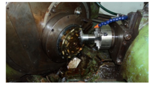
Figure 1: Testing machine
2.2. Cutting insert and cutter head
The cutting inserts that were used in this study were the CVD Ti (C, N) – Al2O3 – TiN coated carbide inserts (SANDVIK). This type of cutting insert has many advantages in industry machining such as: heat resistance stability, mechanical stability, impact resistance, and suitable for final cutting conditions, etc. This material is widely used to manufacture cutting tools for machining process and for machining process the of the gears. The properties of this material in comparison to other cutter materials were presented in Table 1. The geometry of the cutting insert is shown in Figure 2.
Table 1: The properties of several cutter material [21]
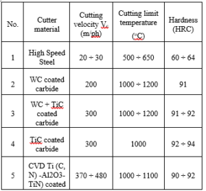
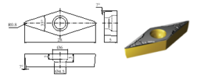
Figure 2: CVD Ti(C, N)-Al2O3-TiN coated carbide insert
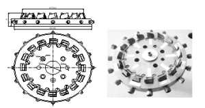
Figure 3: Gleason fine milling cutter head
The tool head for machining gears that was used in this study was a 9-inch Gleason final milling cutter head. This cutter head consists of 16 cutting flutes with 8 external flutes and 8 internal flutes. The tool can be used to machine the gears with module from the module 4 to module 9 as shown in Fig. 3. The geometrical parameters of a flute were shown in Fig. 4 and Fig. 5.
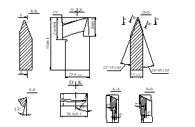
Figure 4: Geometrical parameters of the internal cutting flute of the Gleason cutter head
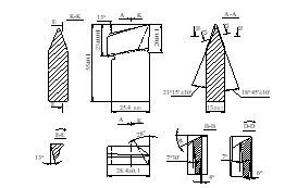
Figure 5: Geometrical parameters of the external cutting flute of the Gleason cutter head
2.3. Experimental workpieces
The workpiece material that was used in this study was 20XM steel (ГOCT 4543-71). The workpiece chemical compositions are analyzed according to ASTM 415-99A-2005 standard was listed in Table 2. Before each experiment, the workpiece was machined according to the detailed drawing of a gear with the following basic parameters: Module: ms = 4.5mm; helix angle bs = 350; number of flutes Z = 27 as shown in Fig. 6 and Fig.7.
Table 2: Main chemical composition of workpiece material %
| C | Si | Mn | Cr | Ni | Mo | Cu | S | P | Fe |
| 0.23 | 0.19 | 0.68 | 0.93 | 0.18 | 0.24 | 0.15 | 0.03 | 0.03 | Balanced |
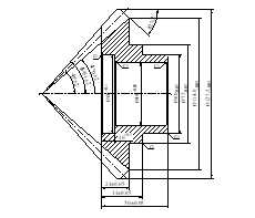
Figure 6: Detailed drawing of a gear workpiece
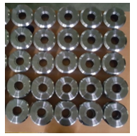
Figure 7: Experimental workpiece
2.4. Measuring system of tool wear
For each experiment, the tool wear was measured using the VHX-6000 digital microscope of Keyence Japan. Fig. 8 indicated the setup of the microscope for measurement of the tool wear. Fig. 9 indicates the measurement position of the flank tool wear (VB).
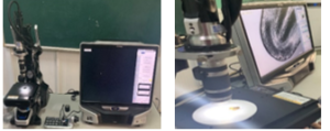
Figure 8: VHX-6000 digital microscope
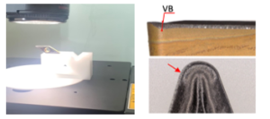
Figure 9: The tool wear of the back in a test
2.5. Experimental matrix
In this study, the experimental plan was designed using Box-Behnken matrix. In this form of planning, each input parameter had three value levels. The input parameters and their levels are presented in Table 3. The experimental matrix was presented in Table 4.
Table 3: Input parameters and their levels
| Parameters | Symbol | Unit | Levels and values | ||
| Velocity of cut | V | m/min | 93 | 117.5 | 142 |
| Feed rate | S | s/tooth | 40 | 50 | 60 |
| Cutting depth | t | mm | 0.25 | 0.50 | 0.75 |
Table 4: Test matrix and results
| No. | Code value | Actual value | VB (µm) | ||||
| V | S | t | V(m/min) | S (s/tooth) | t (mm) | ||
| 1 | -1 | -1 | 0 | 93 | 40 | 0.5 | 57.22 |
| 2 | 1 | -1 | 0 | 142 | 40 | 0.5 | 37.42 |
| 3 | -1 | 1 | 0 | 93 | 60 | 0.5 | 32.95 |
| 4 | 1 | 1 | 0 | 142 | 60 | 0.5 | 82.98 |
| 5 | -1 | 0 | -1 | 93 | 50 | 0.25 | 47.73 |
| 6 | 1 | 0 | -1 | 142 | 50 | 0.25 | 69.42 |
| 7 | -1 | 0 | 1 | 93 | 50 | 0.75 | 29.69 |
| 8 | 1 | 0 | 1 | 142 | 50 | 0.75 | 66.98 |
| 9 | 0 | -1 | -1 | 117.5 | 40 | 0.25 | 37.42 |
| 10 | 0 | 1 | -1 | 117.5 | 60 | 0.25 | 51.25 |
| 11 | 0 | -1 | 1 | 117.5 | 40 | 0.75 | 26.85 |
| 12 | 0 | 1 | 1 | 117.5 | 60 | 0.75 | 59.93 |
| 13 | 0 | 0 | 0 | 117.5 | 50 | 0.5 | 30.10 |
| 14 | 0 | 0 | 0 | 117.5 | 50 | 0.5 | 43.39 |
| 15 | 0 | 0 | 0 | 117.5 | 50 | 0.5 | 30.24 |
3. Analyzed results and discussions
The experimental process was performed according to the experimental matrix as listed in Table 4. The values of tool wear (VB) that were obtained from the experimental process were also listed in this table. The results of ANOVA analysis for the tool wear were presented in Table 5. The influence degree of input parameters on the tool wear, and the influence of the interaction between parameters on the tool wear were shown in Fig. 10 and Fig. 11, respectively.
The analyzed results in table 5, Fig. 10, and Fig. 11 showed that:
The cutting velocity was a parameter with a great influence on the tool wear. When the cutting velocity increased from 93 to 117.5 (m/min), the tool wear decreases slowly, but when cutting velocity increased from 117.5 to 142 (m/min), the tool wear increased quickly.
Other parameter that has a significant influence on the tool wear was feed rate. This conclusion is also consistent with the statement of Fritz et al. [19]. When the feed rate increased, the wear of tool increased.
The cutting depth has little influence on the tool wear. Initially, when increasing the depth of cut, the tool wear decreased slowly, but further increasing the depth of cut, the tool wear increased slowly.
The interaction influence of V, the S, and t on VB were very complex influence. The in Fig. 11 showed clearly this statement.
From the experimental results in Table 4, a tool wear regression model was developed and expressed by Eq. (1). This model was built with a determination coefficient of 0.9169 (R2 = 0.9169). This value was very close to one, which affirmed that this model had high compatibility with the testing data.
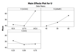
Figure 10: The influence of parameters on the tool wear
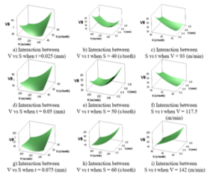
Figure 11: The interaction influence between input parameters on the tool wear
![]()
The tool wear model presented in Eq. (1) was the basis for choosing the value of the input parameters in the investigated area to obtain the minimum value of the tool wear. In addition, this equation may be used to predict the tool wear corresponding to specific values of the cutting velocity, feed rate and depth of cut. The comparing the tool wear in experimental and predicted processes was shown in Fig.12. It was shown that the predicted results of the tool wear were very close to the that one of experimental results. This showed that equation (1) can completely be used to predict the tool wear corresponding to specific values of the input parameters in the investigated area.
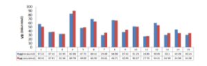
Figure 12: The tool wear when measuring and calculating
4. Optimization process
In order to obtain the optimal values of the cutting velocity, feed rate, and depth of cut to ensure the tool wear with minimum value (tools with maximum life), the constraints for input parameters and the constraints for evaluation criteria should be defined in solving the optimization problem.
The constraints values of the variables are the largest and lowest values of the Box-Behnken matrix. In particular, the constraints of experimental variables were expressed as Eq. (2).
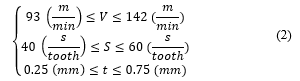
According to references [21, 22] and recommendation by the cutting tool manufacturer, and practical experience in the manufacturing processes, when the tool wear VB exceeds the value 250 (mm), the accuracy of each gear is not guaranteed. This value of VB is chosen as the constraint of VB when performing the optimization process in this study. Thus, the constraint for output parameter was selected by Eq. (3).
![]()
Using the Minitab 16 statistical software to solve the equation (1) to ensure the minimum of tool wear with the constraints as in equations (2) and (3), the optimization graph for the tool wear was obtained and shown in Fig. 13.
Fig. 13 showed that, the optimal value of the cutting velocity, feed rate, and depth of cut are 93.0 (m/min), 59.3939 (s/tooth), and 0.553 (mm), respectively. With the expectation function d = 1.000, it means the probability of this case is up to 100%, and then the tool wear has a minimum value of 32,3679 (µm).
The verified experiments were performed by using these optimized values of the cutting parameters. Based on the adjustment ability of the experimental machine, the value of cutting parameters were only selected in the percentage accuracy (two decimal places). The experiments were carried out with five tests in five gear samples with the workpiece velocity of 93.00 m/min, feed rate 59.40 s/tooth, and cutting depth of 0.55 mm. During the experimental process, other parameters were selected the same when performing the test according to the Box-Behnken matrix. The verified results were stored and listed in Table 6.
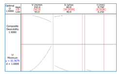
Figure 13: Optimization graph of objective functions for the tool wear
Table 6: Test results verifying the optimal value
| The tool wear when testing, VB | Calculated VB | % deviation | |||||
| Test
1 |
Test
2 |
Test
3 |
Test
4 |
Test
5 |
Average | ||
| 31.12 | 31.83 | 29.68 | 30.85 | 33.66 | 31.43 | 32.37 | 2.9 |
Table 6 indicates that in all 5 tests, the values of the tool wear during the tests are very close to the calculated values of tool wear, the average deviation between the test values and the calculated values was 0.94 mm (about 2.9%). The evaluated results showed that the optimal value of cutting parameters as well as the value of achieved tool wear when performing the optimization process ensured the high accuracy in compared to the actual value.
5. Conclusions
This study was performed to investigate the effect of milling parameters on the tool wear in milling process of the Gleason spiral bevel gear. The conclusion of this study was drawn as following.
(1) The cutting velocity has a great influence on the tool wear, the feed rate was the second factor that influence on the tool wear. The depth of cut has a negligible effect on the tool wear.
(2) The interaction between the velocity of cut, the feed rate, and cutting depth on the wear of tool is very complex.
(3) A regression model showing the relationship between the tool wear and the cutting velocity, feed rate, and the depth of cut was proposed in this study. This model was applied to determine the optimum values of cutting parameters to obtain the minimum value of tool wear. In addition, this model was also used to predict the tool wear in each specific case depending on the cutting parameters. The value of tool wear when calculating was very close to that one when performing experimental.
(4) In this study, by solving the optimization problem, the optimized results of the cutting parameters were determined as following: The cutting velocity was 93.00 m/min, the feed rate was 59.40 s/tooth, and cutting depth was 0.55 mm. When machining with this set of cutting mode, the minimum tool wear that was obtained was about 31.43 (µm).
(5) The experimental method of this study can be used to improve the cost of the machining process through extending the tool life or reducing the tool wear.
Acknowledgement
The authors thank Hanoi University of Industry (HaUI) for the support in the performing the experimental research of this study.
- E. Kilickap, A. Yardimeden, Y. H. Çelik, “Mathematical modelling and optimization of cutting force, tool wear and surface roughness by using artificial neural network and response surface methodology in milling of Ti-6242S”. Applied Sciences, 7(1064), 1-12, 2017, doi:https://doi.org/10.3390/app7101064.
- Y. Li, G. Zheng, X. Zhang, X. Cheng, X. Yang, and R. Xu, “Cutting force, tool wear and surface roughness in high-speed milling of high-strength steel with coated tools”, Journal of Mechanical Science and Technology, 33(11), 5393-5398, 2019, doi:https://doi.org/10.1007/s12206-019-1033-3.
- N. M. Ramezani, A. Rasti, M. H. Sadeghi, B. Jabbaripour, and M. Rezaei Hajideh, “Experimental study of tool wear and surface roughness on high speed helical milling in D2 steel”, Modares Mechanical Engineering, 15(20), 198-202, 2016, doi:http://mme.modares.ac.ir/article-15-8858-en.html.
- G. Selim, T. Dinçer, C. K. Melih, “An Investigation on Surface Roughness and Tool Wear in Turning Operation of Inconel 718”, Journal of Aerospace Technology and Management, 10, e1319, 2019, doi:https://doi.org/10.5028/jatm.v11.1030.
- B. C. Behera, H. Alemayehu, S. Ghosh, P. V. Rao, “A comparative study of recent lubri-coolant strategies for turning of Ni-based superalloy”, Journal of Manufacturing Processes, 30, 541-552, 2017, doi:https://doi.org/10.1016/j.jmapro.2017.10.027.
- R. A. Laghari, J. Li, Z. Xie, S. Q. Wang, “Modeling and Optimization of Tool Wear and Surface Roughness in Turning of Al/SiCp Using Response Surface Methodology”. 3D Research, 9(46), 1-13, 2018, doi:https://doi.org/10.1007/s13319-018-0199-2.
- M. Eckstein, M. Vrabeľ, I. Maňková, “Tool wear and surface roughness evolution in hole making process of Inconel 718”, In Materials Science Forum, 862, 11-17, 2016, doi:https://doi.org/10.4028/www.scientific.net/MSF.862.11.
- T. Nguyen, K. H. Park, X. Wang, J. Olortegui-Yume, T. Wong, D. Schrock, B. Kramer, “The Genesis of Tool Wear in Machining” International Mechanical Engineering Congress and Exposition, 2016, doi:https://doi.org/10.1115/IMECE2015-52531.
- R. Wang, B. Wang, G. C. Barber, J. Gu, J. D. Schall, “Models for prediction of surface roughness in a face milling process using triangular inserts”, Lubricants, 7(9), 1-14, 2019, doi:https://doi.org/10.3390/lubricants7010009.
- N. L. Coppini, A. E. Diniz, F. S. Lacerda, M. Bonandi, and E. A. Baptista, “Internal turning of sintered carbide parts: tool wear and surface roughness evaluation”, Journal of the Brazilian Society of Mechanical Sciences and Engineering, 40(216), 1-7, 2018, doi:https://doi.org/10.1007/s40430-018-1139-z.
- T. D. Hoang, N. T. Nguyen, Đ. Q. Tran, V. T. Nguyen, “Cutting Forces and Surface Roughness in Face-Milling of SKD61 Hard Steel”, Strojniski Vestnik/Journal of Mechanical Engineering, 65(6), 375-385, 2019, doi:https://doi.org/10.5545/sv-jme.2019.6057.
- S. Jeyakumar, K. Marimuthu, and T. Ramachandran, “Prediction of cutting force, tool wear and surface roughness of Al6061/SiC composite for end milling operations using RSM”, Journal of Mechanical Science and Technology, 27(9), 2813-2822, 2013, doi:https://doi.org/10.1007/s12206-013-0729-z.
- N. F. Kundor, N. W. Awang, N. Berahim, “Tool wear and surface roughness in machining AISI D2 tool steel”, Indian Journal of Science and Technology, 9(18), 20-25, 2016, doi:https://doi.org/10.17485/ijst/2016/v9i18/88731.
- M. S. Said, J. A. Ghani, C. H. Haron, S. Yusoff, M. A. Selamat, R. Othman, “Tool wear and surface roughness when machining AlSi/AlN metal matrix composite using uncoated carbide cutting tool”, Materials Science Forum, 773, 409-413, 2014, doi:https://doi.org/10.4028/www.scientific.net/MSF.773-774.409.
- S. M. Ali, N. R. Dhar, “Modeling of tool wear and surface roughness under MQL condition-a neural approach”, Canadian Journal on Artificial Intelligence, Machine Learning & Pattern Recognition, 1(2), 7-25, 2010. doi:https://www.researchgate.net/publication/228744934.
- L. N. Trang, T. X. Thai, N. T. Hai, N. Nhu-Tung Nguyen, “An investigation and analysis of surface roughness and tool wear in dry pocket milling of Aluminum alloy Al7075”, International Journal of Mechanical and Production Engineering Research and Development, 10(2), 1307–1320, 2020, doi:https://www.researchgate.net/publication/340858898.
- B. Christian, K. Fritz, B. Markus, H. Ario, “Analysis and Optimization of Bevel Gear Cutting Processes by Means of Manufacturing Simulation”, Simulation & Modeling Methodologies, Technologies & Appl, AISC, 197, 271–284, 2013, doi:https://doi.org/10.1007/978-3-642-34336-0_18.
- B. Christian, K. Fritz, B. Markus, H. Ario, “Simulation based model for tool life prediction in bevel gear Cutting”, Prod. Eng. Res. Devel, 7, 223–231, 2013, doi:https://doi.org/10.1007/s11740-012-0439-x.
- K. Fritz, K. Alexander, “Tool Life and Productivity Improvement – Through Cutting Parameter Setting and Tool Design in Dry High-Speed Bevel Gear Tooth Cutting”, GEAR TECHNOLOGY, 41-48, 2006.
- K. Fritz, B. Markus, H. Stefan, “Influence of Gear Design on Tool Load in Bevel Gear Cutting”, Procedia CIRP, 1, 66-71, 2012, doi:https://doi.org/10.1016/j.procir.2012.04.010.
- B. T. Long, T. T. Luc, T. S. Tuy, Material processing principles, Science and Technics Publishing House, Hanoi, 2013.
- T. V. Dich, N. T. Binh, N. T. Dat, N. V. Tiep, T. X. Viet, Machinery manufacturing technology, Hanoi Science and Technics Publishing House, 2006.