PV Integrated Recursive Least Mean Square Estimation Based Shunt Active Power Filter

Adv. Sci. Technol. Eng. Syst. J. 5(6), 1171–1177 (2020);
 DOI: 10.25046/aj0506141
This paper proposes a photovoltaic (PV) integrated shunt active power filter (SAPF) for reactive power compensation, uneven loading and compensation of harmonic current. The control of SAPF is implemented by using adaptive based current estimation algorithm to maintain power factor near to unity and source current sinusoidal at source side. The weights are calculated online by recursive least mean square algorithm once the three-phase load current is detected. Secondly, the unit vector templates (UVT) are multiplied with these weights and thus the load current with fundamental active component is derived. PV system enhanced by Maximum Power Point Tracking (MPPT) plays the role of maintaining the dc link voltage constant. Finally, a current control scheme based on hysteresis is used for converter switching and thus the source current to follow reference current precisely. The superiority of the proposed method of compensation of harmonic current and reactive power using SAPF with Recursive Least Mean Square (RLS) algorithm is proved by the simulation results based on MATLAB/SIMULINK.
1. Introduction
The pervasive use of converters based on power electronics has given rise to increasing use of non-linear and inductive loads. The adjacent loads are negatively affected by the voltage variation at point of common coupling (PCC) caused by the harmonic current component of non-linear loads linked to the same network [1-4]. The increased demand of reactive power diminishes the flow capability of active power, and increases feeder losses, whereas the ordinary operation of transformer and generator are adversely affected by the unbalanced system. IEC-61000 and IEEE-519-2014 standards are put into practice to minimize such problems. The introduction of custom power device technology such as unified power quality controller (UPQC), dynamic voltage regulator (DVR), distributed static compensator (D-STATCOM) are effective for the electrical distribution network that faces these issues (unbalanced load, reactive power and harmonics). It is found that SAPF is suitable to efficiently compensate the afore mentioned issues [5].
The control method used to determine the efficacy of the SAPF presented. It mainly relies on the fundamental current extraction algorithm and converter switching generation using extracted reference currents.
The concept here to is to separate load current into three constituent factors. They are fundamental active (iLfp), reactive(iLfq) and harmonic(iLh) components of load current. References [6-9] have reported the low pass and band pass filter (LPF-BPF) based fundamental active current extraction scheme, per phase computation, scheme based on neural network, instantaneous reactive power (IRP) theory, rotating reference frame and instantaneous symmetrical components. Artificial neural network-based extraction scheme requires training of load current datasets for different load conditions which makes system complex and suitable for very specific loads. IRP theory works very well under sinusoidal supply voltage but fails to separate out working and wattless components of the load current under distorted supply condition.
Adaptive filtering techniques are proposed in latest literature because of its merits such as robustness, instinctive monitoring and tracing, less real-time calculation and a fast-dynamic response even under complex load conditions [10-11]. References [12-16] propose various adaptive filtering techniques such as adaptive notch filter, improved sinusoidal notch filter, fuzzy based adaptive control and synchronous adaptive filters. Reference [17, 18] presents least mean square (LMS) based fundamental active current extractor scheme. Least mean squares (LMS) algorithms has the least difficulty and most effectively applied versatile algorithms. The disadvantage of using LMS algorithm is its slow convergence rate. Excellent performance and prominent fidelity make the recursive least square algorithm (RLS) superior, however they accompany expanded intricacy and computational expense. In adaptive filtering applications, RLS approaches Kalman filter with reduced computational complexity in the signal processor. At the cost of requiring more computations, the RLS approach has quicker convergence characteristics compared to LMS algorithm and less error with respect to the unknown system. Reference [19] have reported PV integrated system-based voltage source converter (VSC) to keep a constant voltage at dc link. The development of PV technology has given motivation to the concept of combining clean and free solar energy for SAPF.
This paper proposes a PV integrated 3-phase shunt active filter with recursive least mean square based extractor scheme for fundamental active current extraction by recursively updating the weight of the input signal. The recursive approach finds the filter coefficients that minimize a weighted linear least squares cost function relating to the input signals. Minimization of the total weighted squared error between the desired signal and the output is the main objective of this approach.
It also uses variable forgetting factor to get fast merging rate and less steady state error. The usage of forgetting factor makes the de-emphasis of previous old data as compared to the new data. Moreover, PV system is integrated to keep the voltage of dc link constant. The performance analysis of RLS based SAPF reveals IEEE standard 519 compliant functionality under various operating conditions.
2. System Configuration
The Shunt active filter which act as voltage source converter is coupled to PCC through interfacing inductor Lf. The key functions of the SAPF include a) the elimination of harmonic component of load current thereby maintaining sinusoidal nature of source current with THD<5% b) maintaining source current in phase with pcc voltages achieving near unity pf and c) unbalanced load current compensation by maintaining source currents balanced irrespective of load conditions. The implementation of SAPF requires accurate connection of interlinking inductors, capacitor in the dc link, current and voltage sensors. The control algorithm must be fast enough for the successful functioning of the SAPF. The adaptive RLS algorithm used in this work has higher convergence rate as compared to other variants of least mean square algorithms. Figure 1 indicates the typical illustrative figure of 3-phase SAPF. Notations used in Figure 1 are described in section 2.1.
Three phase (i.e. a, b and c) load currents are determined by means of current sensors. Similarly, source currents, isa-isb-isc are measured. Three voltage sensors are used to measured three phase voltages va-vb-vc at PCC. PLL will determine θ, based on PCC voltages which in turn is used to generate UVTs for the three phase system. Fundamental active current extractor which makes use of RLS based adaptive algorithm as illustrated in figure 2 utilize this θ, to determine iLfp.
The product of UVT and iLfp results in the production of the reference source currents, isaR-isbR-iscR, [19]. These reference source currents along with the instantaneous values of the three phase source currents are fed into the hysteresis controller for the production of gate signals. These gate signals are in turn fed to voltage source inverter (VSI) for the generation of compensating currents which are injected into the system. DC link voltage is regulated by means of the PV array. Economic reliability is enhanced since the VA rating of photovoltaic panel used need not be very high as required for the injection of active power since the compensating currents injected need to provide only for harmonic currents and reactive power.
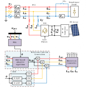
Figure 1: Block diagram of 3-phase SAPF
2.1. Nomenclature
a,b,c : Three Phases
vsa-vsb-vsc : Supply voltage
va-vb-vc : PCC voltages
θ : instantaneous phase angle of fundamental component of supply voltage
Zsa-Zsb-Zsc : Line impedances
iLh,iLfp,ILfq, : Harmonic load current component, Fundamental active and reactive components of load current
iLa-iLb-iLc : Load currents
upa,upb,upc : Unit vector template
ica-icb-icc : Compensating currents
isaR-isbR-iscR : Reference source currents
vdc : DC link voltage
Cdc : Capacitor at dc link

Figure 2: Control diagram for 3-phase SAPF
iLp : Fundamental active load current component’s peak value
iLq : Fundamental reactive load current component’s peak value
iLm5, iLm7 : Peak value of 5th and 7th harmonic components of load current
ic1 : Fundamental compensating current component’s peak value
icm5, icm7 : Peak value of 5th and 7th harmonic components of compensating current
ism1 : Fundamental source current component’s peak value
ism5, ism7 : Peak value of 5th and 7th harmonic components of source current
3. Control Scheme
The LS estimate of the filter coefficient w(n-1) at iteration n-1 is the basic technique behind RLS algorithm. This type of algorithm is known as recursive least mean square algorithm. This algorithm may be viewed as a special case of Kalman filter. Recursive filter is implemented by using the available starting conditions and then update the weight based on new arrived data. This leads to the minimization of cost function, where observed data’s variable length is notated as n.
Cost function where wn is weighting factor and e(n) is error.
This error e(n) can be expressed as,


where P(n) and g(n) represent the inverse input correlation matrix and Kalman gain vector. For algorithm learning, the term which is the forgetting factor plays a very major role, whose value is between 0 and 1.
The value of forgetting factor is closely related with convergence rate and tracking capability. In fixed forgetting factor based RLS algorithm, as increases and its value moves closer to 1, convergence rate increases and at the same time tracking speed will reduce. To improve the tracking capability of the algorithm value must be small which will diminish the convergence rate. These conflicting requirements are met by the usage of a variable forgetting factor RLS algorithm.
3.1. Generation of switching pulses for the operation of SAPF
Based on the three phase supply voltages, the control scheme shown in figure 2 will determine . This generates the three unit vector templates for the system. This UVT along with three phase load currents are the inputs to the control algorithm. The algorithm will generate weights corresponding to the three phase components of active power.
The mean weight magnitude equivalent to the components of active power (wpa, wpb and wpc) from figure 2 is obtained by,
![]()
The dc bus voltage is sensed with the aid of a voltage sensor. This in turn is compared with the set point voltage of the dc bus (vdc), and leads to the generation of the error signal (ve). The MPPT based PI controller’s tuned output (wdc) ensures the steady maintenance of the dc bus voltage at its desired value.
The output of the PI controller at nth sampling instant is indicated below,
![]()
where the gains of PI controller are notated as kp and ki
The sum of mean weight (wavg) and PI controller’s tuned output (wdc) is utilized to find the active component of load current’s weight.

The computation of VSC compensating current is carried out by subtracting the reference source currents (9) from load currents.
4. Performance Validation
MATLAB/SIMULINK platform is used to manifest the performance of the RLS based control algorithm. For various load conditions, validity of the proposed scheme has been checked as mentioned in the next section. The simulation parameters are detailed in Table 1. The SAPF comes into play at t=0.1 sec and the results of the three phase SAPF are as displayed in Figure 3.
Case 1: Steady state performance for Load-I
As shown in the Figure 3, from t=0.1s to 0.2s, undistorted , supplies Load–I which has a Total Harmonic Distortion (THD) of 1.53% and RMS value of 230V. THD and max. value of load current is 27.16% and 1.84 A respectively.
Load current’s fundamental active and reactive component as well as the peak value of fifth and seventh harmonics are shown in Table 2.
Current harmonics is controlled by forcing peak value of fifth and seventh harmonic of compensating current to take a value as shown in Table 2. This will lead to a reduction in THD to 3.05%. Hence peak value of fifth and seventh harmonic of source current are found to be negligible. By ensuring source side pf at unity, enforcement of reactive power compensation is done by controlling the max. value of the compensating current’s fundamental component to be at 0.17A. Allowing for a p-p ripple of 0.2 V, voltage at dc link, vdc is maintained at a mean value of 220.2 V.
Table 1: System Parameters
| System Parameters | Value |
| vpcc(undistorted)/phase | 230V, 50Hz |
| Load – I: | 3-phase rectifier having load : (140+j31.42) Ω ;Sw closed; balanced load |
| Load – II: | 3-phase inductive load having (90+j31.42) Ω ;Sw closed; balanced load |
| Load – III | 3-phase rectifier having (90+j31.42)Ω ;Sw open; unbalanced load |
| Unbalanced load, Zc1 | (10+j3.14) Ω |
| Source impedance, Zs | (0.02+j0.0314) Ω |
| DC link voltage, Vdc | 220 V |
| Interfacing Inductor, Lf | 4mH |
Case 2: Dynamic performance under step change of load
Figure 3 manifests step load change from I to II at 0.2 sec, which demonstrates the SAPF performance under the condition of dynamic load change with the RLS control algorithm. From figure 3, peak value of source current under the transient condition is 2.02A. Values of all parameters in the new steady state condition with Load II is as indicated in Table 2. Compensation ensures that THD becomes well within the limit and also pf being improved to unity.
Under the sudden step load changing condition, voltage at dc link, vdc droops to 215.8 V. The action of PV integration along with the MPPT control algorithm make sure that within 0.07 sec, voltage at dc link is restored to its set point value. The presented algorithm displays a satisfying performance by efficient tracking of the fundamental load current component, iLfp change from 1.28A to 1.90A.
Case 3: Steady state performance for unbalanced loading condition
Figure 3 shows the steady state unbalanced loading condition performance of 3-phase SAPF operating with RLS control scheme. Switch Sw is open at t=0.3sec to introduce the unbalanced loading scenario. The values related to unbalanced load currents and compensating currents for each phase are as indicated in Table 3. Unbalanced loading results in unbalanced compensating currents for the three phases. Each phase caters to the harmonic current and reactive power requirement set forth by the load. Once the load currents under unbalance are compensated, the source currents will automatically become balanced. The THD and max. magnitude for the source’s currents isa, isb and isc are 3.21% and 1.61 A. The voltage at dc link, vdc with p-p ripple of 0.21 V is sustained at a mean value of 221V. Also, the source power factor is kept at unity. This set up ensures unbalanced load compensation by the 3 phase SAPF with the presented control algorithm.
The results for the three cases are summarized in Table 2. From the table, it can be clearly understood that icm5 iLm5 and icm7 iLm7. This reveals harmonic current compensation with source current THD maintained well below the 5% limit. Unity power factor is well kept at supply end via reactive power compensation which is evident from the fact that icm1 iLq. Also unbalanced load current compensation is achieved by the algorithm which ensures that source current is balanced even under unbalanced load conditions. Thus the presented control scheme of 3 phase SAPF based on adaptive RLS algorithm is providing the necessary compensating currents, reactive power and unbalanced load compensation which leads to THD kept within 5% limit and unity power factor (UPF) at supply end.
From table 3, it is clear that convergence time, % steady state error and % THD is less for RLS based algorithm compared to LMS algorithms. Computational complexity is high for RLS algorithm since it considers the estimate of previous samples of output signal, error signal and filter weight. To include the effect of losses, distortion power should be taken into account because of the harmonic inducing nature non- linear loads connected to grid side. Thus the product of displacement power factor and distortion power factor gives the true power factor.
Table 2: Performance of the SAPF with the proposed control algorithm
| Case | Category of load | vpcc | iL (A) | ic (A) | is (A) | %THD | ||||||||
| ILp | ILq | ILm5 | ILm7 | Icm1 | Icm5 | Icm7 | Ism1 | Ism5 | Ism7 | iL | is | |||
| 1 | Load – I
(balanced) |
Undistorted
(THD=1.53%) |
1.22 | 0.14 | 0.25 | 0.13 | 0.16 | 0.24 | 0.13 | 1.28 | 0.01 | 0.01 | 27.16 | 3.05 |
| 2 | Load – II
(balanced) |
Undistorted
(THD=1.53%) |
1.93 | 0.31 | 0.41 | 0.27 | 0.33 | 0.41 | 0.26 | 1.90 | 0.0 | 0.0 | 23.20 | 2.30 |
| 3 | Load – III
(unbalanced) |
Undistorted
(THD=26.5%) |
1.78 | 0.21 | 0.28 | 0.34 | 0.25 | 0.27 | 0.34 | 1.61 | 0.01 | 0.01 | 31.6 | 3.21 |
| 1.33 | 0.31 | 0.37 | 0.36 | 0.35 | 0.37 | 0.36 | 1.61 | 0.01 | 0.01 | 34.9 | 3.21 | |||
| 0.45 | 0.2 | 0.13 | 0.31 | 0.40 | 0.12 | 0.31 | 1.61 | 0.01 | 0.01 | 34.8 | 3.21 | |||
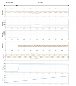
Figure 3: Simulation results for operation of the three phase SAPF with proposed algorithm
Table 3: Performance comparison of RLS algorithm with LMS algorithm [18]
| Function | NLMS | VSSLMS | RLS |
| Convergence time | 0.3 sec | 0.12 sec | 0.06 sec |
| Steady state error | 2.11 | 0.85 | 0.56 |
| THD | 4.32 | 2.13 | 1.48 |
| Complexity | Less | Less | High |
Table 4: Power factors under varying load conditions
| Case | Load | Distortion Factor | Displacement factor | True Power Factor |
| 1 | Load – I
(balanced) |
0.9995 | 0.9998 | 0.999 |
| 2 | Load – II
(balanced) |
0.9997 | 0.9997 | 0.999 |
| 3 | Load – III
(unbalanced) |
0.9995 | 0.9998 | 0.999 |
The equations (10-12) implies that the overall power factor gets diminished by the term cos γ. This leads to the conclusion that the average power transferred to the load gets diminished by cos γ, which depends on harmonic distortion induced in load current by the non-linear loads.

The proposed SAPF configuration, maintains displacement power factor at 0.999 and the distortion power factor at near unity, for all the analysed load conditions. This leads to a magnitude of 0.999 for the true power factor. Table 3 manifests the true power factor under varying load conditions considered here.
5. Conclusion
This paper illustrates the performance aspects of PV powered RLS based shunt active power filter control utilizing the MATLAB/SIMULINK platform. Fundamental active components reference from the load currents are separated by the control law, based on the load currents, phase angle and reference currents of the previous sample. Load current’s fundamental active component is only drawn from the source side and this is performed by the control system by ensuring that source currents track the reference currents with minimum steady state error. This makes the SAPF satisfy the reactive and harmonic power requisite of the considered non- linear load. Even under unbalanced loading condition, the source currents are in perfect balance. The put forward theory is validated by the results which shows that the source currents are drawn at UPF and they comply with the IEEE standard 519. Also, it is shown that dc voltage is maintained constant using PV integration into the network. With RLS algorithm, the 3-phase SAPF ensures sinusoidal and balanced supply currents which are maintained at UPF at various load conditions along with THD maintained under the 5% limit.
- B. Singh, A. Chandra and K. Al-Haddad, “Power Quality: Problems and Mitigation Techniques”, John Wiley and Sons, 2015.
- R. Rajagopal, K. Palanisamy, S. Paramasivam, “A Technical review on control strategies of active power filters”, IEEE 2018 International Conference on Emerging Trends and Innovations In Engineering And Technological Research (ICETIETR), TIST, Cochin. 1-6, 2018, doi: 10.1109/ICETIETR.2018.8529008.
- K.S. Rajesh, S.S. Dash, Ragam Rajagopal, R.Sreedhar “A review on control of ac microgrid”, Renewable & Sustainable Energy Reviews, 71, 814-819, 2017, doi: 10.1016/j.rser.2016.12.106.
- K.S. Rajesh, S.S. Dash, Ragam Rajagopal, “Hybrid improved firefly-pattern search optimized fuzzy aided PID controller for automatic generation control of power systems with multi-type generations”, Swarm and Evolutionary Computation, 44, 200-211, 2019, doi:10.1016/j.swevo.2018.03.005.
- S. R. Arya and B. Singh, “Performance of DSTATCOM using leaky lms control algorithm”, IEEE J. Emerging Selected Topics in Pow. Electron., 1(2), 104-113, 2013, doi: 10.1109/JESTPE.2013.2266372.
- B. Singh, K. Kant, and S. R. Arya, “Notch filter-based fundamental frequency component extraction to control distribution static compensator for mitigating current-related power quality problems,” IET Power Electronics, 8(9), 1758-1766, 2015., doi: 10.1049/iet-pel.2014.0486.
- B. N. Singh, B. Singh, A. Chandra, and K. Al-Haddad, “Design and digital implementation of active filter with power balance theory,” Proc. Inst. Elect. Eng.—Elect. Power Appl., 52(5), 1149–1160, 2005, doi: 10.1049/ip-epa:20050097.
- D. Chen, “A Novel Cost-Effective Two-Level Inverter with Combined Use of Thyristors and IGBTs”, Journal of Electrical Engineering and Technology, 13(1), 152-159, 2018, doi:10.5370/JEET.2018.13.1.152
- K. Karaarslan, B Arifoglu, E Beser, S Camur, “Level Number Effect on Performance of a Novel Series Active Power Filter Based on Multilevel Inverter”, Journal of Electrical Engineering and Technology, 13(2), 711-721,2018, doi: 10.5370/JEET.2018.13.2.711.
- B. Singh ,Jitendra Solanki, “An Implementation of an Adaptive Control Algorithm for a Three-Phase Shunt Active Filter”, IEEE Transactions on Industrial Electronics, 56(8), 2811-2820, 2009, doi: 10.1109/TIE.2009.2014367.
- M. Qasim , Parag Kanjiya , Vinod Khadkikar, “Optimal Current Harmonic Extractor Based on Unified ADALINEs for Shunt Active Power Filters”, IEEE Transactions on Power Electronics, 29(12), 6383-6393, 2014, doi: 10.1109/TPEL.2014.2302539.
- M. Qasim, P. Kanjiya and V. Khadkikar, “Optimal Current Harmonic Extractor Based on Unified ADALINEs for Shunt Active Power Filters,” IEEE Transactions on Power Electronics, 29(12), 6383-6393, 2014, doi: 10.1109/TPEL.2014.2302539.
- R. R. Pereira , C. H. da Silva , L. E. Borges da Silva , G. Lambert-Torres, “Application of adaptive filters in active power filters”, 2009 Brazilian Power Electronics Conference, Bonito-Mato Grosso do Sul, 770-774, 2009, doi: 10.1109/COBEP.2009.5347654.
- K. Sebasthirani , M. Manimegalai, “Recent Advances in Shunt Active Power Filter with Recursive Least Square Algorithm and its Applications”, 2018 2nd International Conference on Trends in Electronics and Informatics (ICOEI), Tirunelveli, 1288-1293, 2018, doi: 10.1109/ICOEI.2018.8553806.
- R. Kumar Agarwal, Ikhlaq Hussain, Bhim Singh, “Dual-function PV-ECS integrated to 3P4W distribution grid using 3M-PLL control for active power transfer and power quality improvement”, IET Renewable Power Generation, 12(8), 920-927 ,2018, doi: 10.1049/iet-rpg.2016.0723.
- M. Badoni , Alka Singh ,Bhim Singh, “Comparative Performance of Wiener Filter and Adaptive Least Mean Square-Based Control for Power Quality Improvement”, IEEE Transactions on Industrial Electronics, 63(5), 3028-3027,2016, doi: 10.1109/TIE.2016.2515558.
- R. Rajagopal, K Palanisamy, S.Paramasivam, “Comparative Performance of Normalized LMS and Variable Step Size LMS based Control for Shunt Active Filtering,” 2019 9th International Conference on Advances in Computing and Communication (ICACC), Kochi, India , 136-141, 2019, doi: 10.1109/ICACC48162.2019.8986184.
- R. Belaidi, A. Haddouche, M. Fathi, M. M. Larafi and G. M. Kaci, “Performance of grid-connected PV system based on SAPF for power quality improvement,” 2016 International Renewable and Sustainable Energy Conference (IRSEC), Marrakech, 542-545, 2016, doi: 10.1109/IRSEC.2016.7984050.
- R. Rajagopal, K. Palanisamy and S. Paramasivam, “Shunt Active Filter Based on 7-Level Cascaded Multilevel Inverter for Harmonic and Reactive Power Compensation” Journal of Electrical Engineering & Technology, Springer, 14(4), 1543-1551, 2019, doi: 10.1007/s42835-019-00201-1.