Advanced Design of Current-mode Pass-band Filter using Ant Colony Optimization Technique

Adv. Sci. Technol. Eng. Syst. J. 5(6), 995–1000 (2020);
 DOI: 10.25046/aj0506119
Ant Colony Optimization (ACO) algorithm, a well-known robust technique to solve easily both a simple and multiple objective optimization problems. This article presents an application of the ACO in order to achieve the optimal sizing of analog circuit. The proposed technique is employed to optimizing the sizing of a positive second-generation current conveyor (CCII+). Results show better objective functions than previously achieved by other optimization procedure. PSPICE simulations are used to confirm the validity of the reached optimal results and the accuracy of the proposed procedure.
1. Introduction
Current Conveyor (CC) represents the first construction block developed for current signal processing [1]. Two years later, in 1970, another variant of a CC, namely, Second Generation Current Conveyor (CCII) was published [2].
Recently, a Current Conveyor is seen as a good alternative for the voltage-mode. CC can be widely employed in different applications. The CCII is the most popular configuration [3].
Despite the number of positive proprieties ensured by the CCS [4], it seems that designing integrated CC circuits with high performance is in effect still open particularly in CMOS technology [5].
Currently, an important interest has been devoted to achieve the best sizing of the analog component efficiently and with high accuracy. Some (meta) heuristics were used in the scientific publications such as Genetic Algorithms (GA) [6, 7], Ant Colony Optimization (ACO) [8, 9], Particle Swarm Optimization (PSO) [10], Differential Evolution algorithm (DE) [11], Simulated Annealing (SA) [12] and Artificial Bee Colony Algorithm (ABC) [13, 14].
ACO algorithm is proposed in this work, with view to get an optimal design of positive second-generation current conveyor (CCII+). To this end, we applied three of the most important variants of ACO, specifically, the Ant System (AS), the Min-Max Ant System (MMAS) and the Ant Colony System (ACS). In fact, the ACO has already efficiently been used to treat real optimization problems, particularly in the analog circuit area.
A high performance CCII+ depends on the high-end cut-off frequency for the current waveform (Fci) and the input impedance at port X. Hence, two objectives functions are taken into consideration: achieve a low input resistance RX and a very high cut-off frequency Fci. However, the suggested technique is a mono-objective one, to this end; the optimization process is treated using two distinct manners; firstly, each objective function is solved separately. In the second way, a mono-objective problem is considered by using a weighting technique.
This paper is organized in the following manner: The second section is about a detail description of the ACO technique. The third section proposes an example for the optimal sizing of CCII+. Then, a comparison with some similar works and simulation results are represented in the fourth section. Through the fifth section, the optimized CCII+ is exploited in order to form a current mode filter. Finally, the sixth section is the conclusion.
2. The ACO Technique Presentation
Ant Colony Optimization (ACO) is a nature-inspired algorithm, used to resolve various hard problems. The use of ACO has proved a capacity to deal with complex optimization problems successfully, for instance we can cite the traveling salesman problem (TSP) [15], vehicle routing problem [16], the quadratic assignment problem (QAP) [17].
The ACO takes inspiration from the real ant colonies behavior. The fundamental idea of this metaheuristic consists in simulating the social intelligence of ants in searching the shortest road from the nest and a source of food. In fact, real ants communicate indirectly through trails of chemical pheromone. Concretely, the agents of the colony deposit pheromone on the road to determine certain favorable route to be pursued by other ants [18].
2.1. Ant System
« Ant System » (AS) is the basic variant of the ACO. The modelling approach to resolve a given optimization problem is established as follows:
Ants choose the vertex to travel to by applying the state transition rule [19, 20]. Ant k in node a will move to vertex b according to the probability offered by (1):
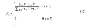
while corresponds to the list of possible moves, which are possible for ants starting form vertex a, represents the intensity of the trace associated to brink (a, b). α and β identify the relative impact of the trace intensity and the visibility value, ηab .
where
![]()
The dab represents the distance between nodes a and b
The pheromone is updated by means of formula (3), when all agents of the colony construct their path:
![]()
While ? corresponds to the pheromone decay parameter, m represents the number of ants, and Δτabk is the amount of pheromone deposited by ant k on brink (a, b):

Q is a constant; Lk represents the tour length built by ant k.
2.2. Min-Man Ant System
The Min-Max Ant System is an adjustment of the AS [21].
Min-Max Ant System (MMAS) is designed to attain the best result. To this end, only the optimal result is authorized to intensify the pheromone quantity. In fact, MMAS uses an instrument to border the trace intensity, and so that avoid the premature stagnation.
MMAS presents some new features and they are as follows:
- Only the ants that produced the best solution are allowed to update trails;
- To avoid stagnation, MMAS introduces upper and lower bounds so that the pheromone intensities lie inside the interval [τmin, τmax];
- In each brink, the trail strength is initialized to τmax.
2.3. Ant Colony System
The Ant Colony System (ACS) algorithm incorporates three main differences with respect to the AS algorithm:
- ACS algorithm uses a parameter q0 (0≤q0≤1), which controls the tuning between exploitation and exploration. thus, the probability that ant moves to node b is given by this rule:

where q is a random variable evenly distributed in [0, 1]
- The global pheromone update is applied only to edges that form part of the best solution, as in the following:
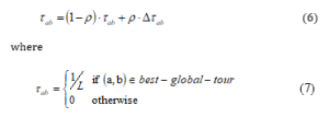
- The updating of local pheromone is applied when each ant produce a solution:
![]()
The procedure of the ACO technique can be illustrated by means of the flowchart bellow:
3. Application of the ACO to the optimal sizing of CCII+
CCII is the most popular configuration of CCs; it replaces the conventional OPAMP in different applications as for example active filters, oscillators, and analog signal processing.
The CCII is three terminal devices; the current conveyor’s response is illustrated by expression (9) [22]:

The voltage at node X is duplicated from the voltage applied at node Y. Similarly, the current at Z port is copied from the current flowing through node X. A positive Z output current conveyor is considered when and it is denoted CCII+. For optimal circuit performance, it is desirable to have very high impedance on Y and Z nodes and small Rx, i.e. the resistance on X [22].
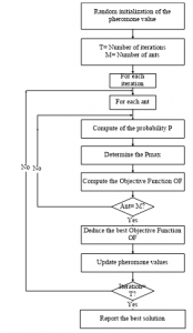
Figure 1: Flowchart of ACO
In this work, the ACO is used to optimize the performances of a positive second-generation CMOS current conveyor (CCII+) (figure2). Optimizing the most affecting parameters of the current conveyor is highlighted:
This optimization problem is resolved using two methods; in the first one, two mono objective function are considered. The objective functions are:
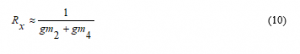
- Minimize the Rx, which represents the X-port input parasitic resistance
- Maximize the Fci, which represents the current high cut off frequency
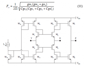
Figure 2: A positive second generation current conveyor
In the second method, the proposed objective function allows simultaneously minimizing Rx and maximizing Fci, and it is configured as:
![]()
The MOS transistors size represents the geometric variables that will be considered: the gates widths (WN and WP) and channels lengths (LN, and LP). The binding functioning conditions require that all the transistors of CCII+ must function in the saturation mode. So that, the main constrain of the optimization problem are presented by expressions (13) and (14):
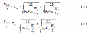
where Cox, μN, and μP are MOS technology parameters. VTN and VTP denote threshold voltages of NMOS and PMOS transistors respectively. The employed supply voltages are Vss/VDD= -2.5V/2.5 V and a bias current, Ibias=100 μA.
4. Results and Discussion
The proposed variants of the ACO technique were applied to deal with the optimal sizing of CCII+. The optimization technique works on C++ codes.
4.1. Optimization problem result using tow separated objective functions
The optimal values for the parameters of CCII+ achieved by the ACO algorithms and the circuit’s performances linked with these values are indicated in tables 1 and 2.
Table 3 presents the performances provided by the AS, the MMAS and the ACS techniques versus to the ones ensured by Particle Swarm Optimization (PSO) and the Genetic Algorithm (GA) algorithms.
Table 1: the obtained results for RX
| LN
(µm) |
WN
(µm) |
LP
(µm) |
WP
(µm) |
RX-min (Ω) | ||
| Opt. | Sim. | |||||
| AS | 0.59 | 36.60 | 0.35 | 58.64 | 333.01 | 315.89 |
| MMAS | 0.60 | 36.34 | 0.35 | 59.00 | 335.63 | 318.69 |
| ACS | 0.59 | 36.68 | 0.35 | 59.00 | 332.65 | 315.19 |
Table 2: the obtained results for Fci
| LN
(µm) |
WN
(µm) |
LP
(µm) |
WP
(µm) |
Fci-max (GHz) | ||
| Opt. | Sim. | |||||
| AS | 0.55 | 5.48 | 0.35 | 9.52 | 1.795 | 1.739 |
| MMAS | 0.55 | 5.60 | 0.35 | 9.60 | 1.775 | 1.731 |
| ACS | 0.55 | 5.44 | 0.35 | 9.50 | 1.801 | 1.754 |
The results of the simulation under SPICE for Rx and Fci employing the optimal results acquired by the suggested techniques for CCII+ are exposed in figures 3 and 4. We can observe that simulation results are in good correspondence with theoretical values achieved by the ACO technique.
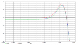
Figure 3: Variation of resistance (ohm) versus frequency (Hz) employing AS,MMAS and ACS

Figure 4: Current gain (dB) versus frequency (Hz) employing AS,MMAS and ACS
Table 3: Comparison results
| ACS | PSO[23] | GA[23] | |
| RX-min (Ω) | 332.65 | 464 | 510 |
| Fci-max (GHZ) | 1.801 | 1.751 | 1.541 |
It is shown that the three variants of the ACO algorithm offer similar results. The comparison with two techniques belonging to metaheuristics indicates that the ACS accomplished the greatest results with regard to objectives compared to Particle Swarm Optimization (PSO) and the Genetic Algorithm (GA) algorithms.
4.2. Optimization problem result using weighting approach:
The optimal physical parameters values of MOS transistors achieved employing the three variants of ACO algorithm are given in table 4. The comparison of the acquired results with those obtained by another metaheuristic namely, particle swarm optimization (PSO) algorithm, shows that ACS could reach a greatest Fci value. However, PSO could achieve a smaller RX value.
Table 4: Optimal parameter values and optimization results for RX and Fci
| LN
(µm) |
WN
(µm) |
LP
(µm) |
WP
(µm) |
Fci-max
(GHz) |
RX–min
(Ω) |
|
| AS | 0.58 | 7.95 | 0.35 | 13.00 | 1.446 | 711.42 |
| MMAS | 0.59 | 8.08 | 0.35 | 13,00 | 1.420 | 708.75 |
| ACS | 0.55 | 7.53 | 0.35 | 12.97 | 1.531 | 721.08 |
| PSO-2S [24] | 0.52 | 14.30 | 0.35 | 23.62 | 1.358 | 444 |
The following table presents the simulation results:
Table 5: The optimal results for Rx and Fci
| Fci_max
(GHz) |
RX_min
(Ω) |
|||
| Opt. | Sim. | Opt. | Sim. | |
| AS | 1.446 | 1.495 | 711.417 | 825.896 |
| MMAS | 1.420 | 1.479 | 708.75 | 825.896 |
| ACS | 1.531 | 1.552 | 721.085 | 827.704 |
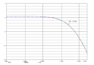
Figure 5: Current gain (dB) as a function of frequency (Hz) employing AS,MMAS and ACS
The figure 5 gives the SPICE simulation for current gain (in dB) as a function of frequency, and the figure 6 presents the SPICE simulation results for RX (in ohm) as a function of frequency and this by employing the acquired optimal values by the three proposed variants of ACO algorithm for CCII+.
5. A Current Mode Filter based on the CCs
A second order filter can be implemented based on the use of simulated inductance [25]. In fact, Current conveyors present the basis of simulated inductance topology. Figure 7 shows a current mode active filter constituted of 4 current conveyors and two capacitors [26].
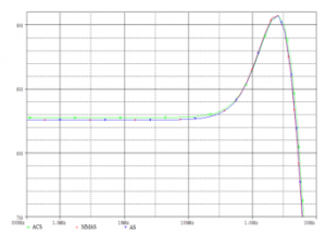
Figure 6: Variation of Rx (ohm) as a function of frequency (Hz) employing AS,MMAS and ACS

Figure 7: Current- mode pass-band filter
The quality factor and the resonance frequency of this filter are respectively presented by:
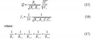
RX1, RX2, RX3 and RX4 represent the parasitic resistances on port X of the considered CCII+.
The considered filter is simulated using SPICE, and it is designed based on the optimized CCII+ with optimal sizes determined by ACS for this cases:
- Firstly, it is designed by employing the obtained CCII+ offering the maximum Fci.
- Secondly, it is designed by employing the obtained CCII+ offering the minimum RX.
- Finally, it is designed by employing the obtained CCII+ offering simultaneously maximum Fci and minimum RX.
The optimal parameters values of MOS transistors for the three cases are summarized in the table 6.
Table 6: Optimal physical parameters values of MOS transistors
| Minimum RX | Maximum Fci | Minimum RX and Maximum Fci | |
| WN/ LN (µm) | 36.68/0.59 | 05.44/0.55 | 7.53/0.55 |
| WP/ LP (µm) | 59.00/0.35 | 09.50/0.35 | 12.97/0.35 |
Figure 8 shows the SPICE simulation of the filter gain, where C1=C2=0.1pF.
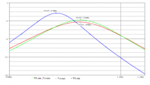
Figure 8: Resonance frequency of the second order current mode band-pass filter
The resonance frequencies reached by the ACS are presented in the following table; we can observe that the best resonance frequency of the current mode second order band pass filter is recorded in the third case.
Table 7: The obtained resonance frequencies
| RX-min | Fci-max | RX-min and Fci-max | ||
| fo (MHz) | 497.896 | 641.389 | 647.781 |
6. Conclusion
In this work, the Ant System (AS), the Min-Max Ant System (MMAS) and the Ant Colony System (ACS), which are the most important variants of Ant Colony Optimization technique, are applied in order to optimize the sizing of conventional CMOS CCII circuit. The performances of a CCII+, especially the current high cut off frequency and the X-port parasitic resistance are optimized. The acquired results prove that the ACO algorithm offers a competitive optimizing capability for the design of CCII+. Then, the improved CCII+ structure was utilized as an elementary block to build current mode band -pass filter. SPICE simulations and comparison with already published works were highlighted.
- K. C. Smith, A. Sedra. “The Current Conveyor-A new circuit building block” Proceedings of the IEEE, 56(8), 1368-1369, 1968. DOI: 10.1109/PROC.1968.6591
- A. Sedra, K. C. Smith, “A Second-Generation Current Conveyor and Its Applications” IEEE Transactions on Circuits Theory, 17(1), 132-134, 1970. DOI: 10.1109/TCT.1970.1083067
- D. Moro Frias, “Design and Applications of CMOS Current Conveyors,” Master in electronics science, National Institute for Astrophysics, Optics and Electronics, 2008.
- P. Brandstetter, L. Klein, “novel wien bridge oscillator design using functional block structure with current conveyors”, Advances in electrical and electronic engineering, 10(1), 13-16, 2012. DOI: 10.15598/aeee.v10i1.556
- A. Chatterjee, M. Fakhfakh, P. Siarry, “Design of second-generation current conveyors employing bacterial foraging optimization”, Microelectronics Journal, 41(10), 616-626, 2010. doi:10.1016/j.mejo.2010.06.013
- J. B. Grimbleby, “Automatic analogue circuit synthesis using genetic algorithms”, IEE Proceedings-Circuits, Devices and Systems, 147(6), 319-323, 2000. DOI: 10.1049/ip-cds:20000770
- A. El Beqal, B. Benhala, and I. Zorkani, A Genetic algorithm for the optimal design of a multistage amplifier, Int. J. of Electrical and Computer Engineering (IJECE), 10( 1), 129-138, 2020. DOI: 10.11591/ijece.v10i1
- B. Benhala. Sizing of an inverted current conveyors by an enhanced ant colony optimization technique, Conference on Design of Circuits and Integrated Systems (DCIS), Granada, pp. 1–5, 2016.
- L. Kritele, B. Benhala, and I. Zorkani. Ant Colony Optimization for Optimal Analog Filter Sizing, Chapter 10, Book: Focus on swarm intelligence research and applications, Eds., B. Benhala, P. Pereira and A. Sallem, NOVA Science Publishers, 193–220, 2017.
- F. T. S. Chan, M. K. Tiwari, Swarm Intelligence: focus on ant and particle swarm optimization, I-Tech Education and Publishing, 2007
- I. El hajjami, B. Benhala, and H. Bouyghf. Optimal Design of RF Integrated Inductors via Differential Evolution Algorithm, 1st International Conference on Innovative Research in Applied Science, Engineering and Technology (IRASET), Meknes, Morocco, pp. 1-6, 2020.
- M. Fakhfakh, M. Boughariou, A Sallem and M Loulou, Design of Low Noise Amplifiers through Flow-Graphs and their Optimization by the Simulated Annealing Technique. Book: Advances in Monolithic Microwave Integrated Circuits for Wireless Systems: Modeling and Design Technologies, IGI global, 2012.
- B. Benhala, P. Pereira, A. Sallem, (Editors), Focus on swarm intelligence research and applications, NOVA Science Publishers, 2017.
- B. Benhala. Artificial bee colony technique for optimal design of folded cascode OTA, 2018 International Conference on Applied Mathematics and Computer Science, ICAMCS 2018, Paris, 59-64.
- Y. Jinhui, S. Xiaohu , M. Maurizio and L.Yanchun, “An ant colony optimization method for generalized TSP problem”, Progress in Natural Science, 18(11), 1417-1422, 2008. doi: 10.1016/j.pnsc.2008.03.028.
- Qi Chengming, “Vehicle Routing Optimization in Logistics Distribution Using Hybrid Ant Colony Algorithm”, TELKOMNIKA Indonesian Journal of Electrical Engineering, 11(9), 5308-5315, 2013. doi: 10.11591/telkomnika.v11i9.3284.
- L. M Gambardella, E. D Taillard, M. Dorigo. Ant colonies for the quadratic assignment problem. The Journal of the Operational Research Society, 50(2), 167–176, 1999. doi:10.1057/palgrave.jors.2600676.
- M. Dorigo, M. Birattari, and T. Stützle, “Ant colony optimization: artificial ants as a computational intelligence technique”, IEEE computational intelligence magazine, 1(4), 28-39, 2006. doi:10.1109/CI-M.2006.248054.
- M. Dorigo and S. Krzysztof, An Introduction to Ant Colony Optimization, IRIDIA, 2006. doi: 10.1162/106454699568728.
- M. Dorigo, G. DiCaro and L. M. Gambardella, “Ant algorithms for discrete optimization”, Artificial Life Journal, 5(2), 137-172, 1999.
- T. Stützle, H. Hoos, “MAX-MIN Ant System”, Future Generation Computer System, 16(2000), 889-914.
- V.C. Gaudet, “Design of a CMOS current conveyor-based field-programmable analog array”, Master of applied science, Department of electrical and cornputer engineering, University of Toronto, 1997.
- B. Benhala, “Metaheuristic Techniques for the Analog Circuits Performances Optimization-A comparison Issue”, WSEAS Transactions on Circuits and Systems, 14(20), 173-181, June 2015,
- A.El Dor, M. Fakhfakh, P. Siarry, “Performance optimization of CMOS second generation current conveyors using a multi-swarm algorithm”, International Journal of Electronics and Communications (AEÜ), 8(68), 496-503, 2014. DOI: 10.1016/j.aeue.2013.12.007
- A. Fabre, O. Saiid, F. Wiest, and C. Bouchern, “High frequency high-Q bICMOS current-mode bandpass filter and mobile communication application”, IEEE Transactions on Circuits and Systems-I, 33(4), 839–842, 1998. DOI: 10.1109/4.663567
- S.B. Salem, M.Fakhfakh, D.S.Masmoudi, M.Loulou, P.Loumeau and N.Masmoudi, “A High Performances CMOS CCII and High Frequency Applications”, Journal of Analog Integrated Circuits and Signal Processing, Springer US, 49(1), 2006. doi.org/10.1007/s10470-006-8694-4
No related articles were found.