NPC five level inverter using SVPWM for Grid-Connected Hybrid Wind-Photovoltaic Generation System

Adv. Sci. Technol. Eng. Syst. J. 5(6), 981–987 (2020);
 DOI: 10.25046/aj0506117
This paper covers a new topology, a synchronous wind turbine generator, and a solar photovoltaic generator. The Permanent Magnet Synchronous Generator is linked to the grid by back-to-back voltage source converters (BtB VSC), consisting of a two-stage rectifier and a five-stage Neutral Point Clamped inverter, operated by the Space Vector Pulse Width Modulation technique. A solar photovoltaic system has a direct interface with the capacitor of the DC link of the BtB VSCs, with no additional DC/DC conversion stage, while the efficiency of the system is maximized. This work features a Perturb and Observe algorithm Maximum Power Point Tracking for to extract the optimum power from both wind turbine and solar PV generator. The application of Space Vector Pulse Width Modulation control scheme is used for harmonics compensation THD. A proportional integral regulator is used to regulate the DC link voltage. A prototype is tested under various conditions, wind velocity variations as well as under several photovoltaic solar isolations. The present work has been treated using Matlab/Simulink. Simulation results proved efficiency provided by this controlling approach: reduced distortion of harmonic and increased power factor.
1. Introduction
Today, the major energy sources used for generating electricity are fossil fuel resources [1]. To reduce the dependency on fossils based energy it necessary for power generation to move towards the renew- able resources including solar energy, wind power, hydroelectricity, and biomass. In literature, most of the distributed production sys- tems are uniquely focused on one type of sustainable resource, e.g., a wind power like in [2] or solar power like in [3].
The combination and the penetration of the renewable resources, face considerable challenges due to growing power industry. The injection into the grid of the energy yielded by wind and solar photo- voltaic generators, is proven to be one of the technological solution [4, 5]. Their combination offers additional benefits such as increas- ing the overall operational efficiency and power reliability, optimal use of lands resources, and improves the capital investments [5]. Grid-connected wind/Photovoltaic (PV) cogeneration is not largely discussed [6]–[7], whereas in literature, most of wind-PV hybrid systems are proposed for standalone off-grid applications [5]. The optimization method of generation of power using hybrid system used for battery charging is developed in [8], to increase the stability
and efficiency. In [9], the author have proposed a small scale hybrid solar- wind power generation system to reduce Electricity shortage in Egypt.
Much research was conducted to track maximum power point (MPP) of the wind using methods based on Perturb and Observe (P&O) algorithm [6], neural network technique, or other approaches based on fuzzy logic. Due to the nonlinear voltage-current proper- ties of PV solar panels, the necessity of MPP tracking has become apparent. MPP tracking schemescan be accounted for as perturb and observe (P&O), incremental conductance method, Fractional Open- Circuit Voltage, Neural Network, Fuzzy Logic Control, Current Sweep [10]. The combination of multilevel inverter and renewable energy sources are advantageous. In [11], the authors have proposed a hybrid cascaded nine level inverters for photovoltaic applications. The proposed system in [12] are based on Maximum Power Point Tracking (MPPT) combined with multilevel inverter to achieve the maximum power. In [6], the system comprises back-to-back voltage source converters with no extra dc/dc conversion stages to connect wind and photovoltaic generators to the power grid. Moreover, the control of the currents on the machine- and grid- side are carried out using hysteresis regulators, introducing higher harmonic contents from the variable switching frequency. The objective in [13] is to The mechanical equation is as shown below:
by employing a new control technique in order that it is possible to transfer maximum active power from the PV to the grid without injecting harmonics. The study proposes in [14, 15] a control strat- egy for a single-phase, three-phase photovoltaic system connected to a distribution network. The proposed technology is based on the modification of the conventional control in current mode to adjust the power factor of the photovoltaic system and control the voltage of the converter link.
This paper extends the work originally presented in ICEIT’4 [2], where the modeling and simulation of a wind turbine string, based on a vector-controlled five-level inverter, was presented. Its objec- tive was the optimization of the energy produced, adjust the DC link and control power transferred into the grid. Motivated by advan-
Where: Rs and Ls are stator-winding resistance and inductance, re- spectively, Id and Iq are the stator currents, Ω is Rotational speed of the PMSG, ϕ is stator phase magnetic flux, fc and J are the friction coefficient and motor inertin, respectively. ϕf : the flux generated by the permanent magnets across stator windings, Cm is the mechanical torque .
2.3 Photovoltaic Generator
The model of the PV generator is presented in Appendix whereas it is modeled as following:
tages of hybrid production systems, presented paper covers a new topology to interface both is Permanent Magnet Synchronous Generator (PMSG)-based wind energy and PV generators with power
grid. Note a blocking diode is series connected with each PV string to avoid reverse flow of current. Two P&O algorithms, namely P&O Wind and P&O PV, are used to optimize the energy extracted by turbine and solar system, respectively. Note that perturbations could impact correct operation of the receivers attached to the grid if the voltage output wave is not sinusoidal. To avoid this problem, we have implemented in this chain a two-stage rectifier followed by a five-stage Neutral Point Clamped (NPC) inverter regulated by the Space Vector Pulse Width Modulation (SVPWM) technique, with- out additional DC/DC conversion stages[16]. The converter control strategy is detailed in which the presented study was treated using Matlab/Simulink. Simulation results proved efficiency provided by this controlling approach: decrease distortion of harmonic and increased power factor.
2. Wind Photovoltaic Generator Side Model
2.1 Wind turbine model
Mechanical energy absorbed by a wind turbine is defined by [2]:
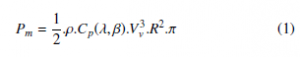
where: Cp is the coefficient of the rotor that is a non-linear function of the tip speed ratio λ and the pitch angle of blades β, R and Vv are the radius of blades and the wind speed, respectively.
2.2 PMSG model
PMSG in the dq marker is modelised using these equations [2]:
The Iop–Vop characteristics of the PV array, there is an optimal operating point (Iop–Vop) corresponding to the maximum generated PV power, at any solar irradiance level.
3. Control Strategy
The suggested wind-PV system appliances two appropriate con- trol techniques for machine-side Voltage Source Rectifier Control (VSRC) and grid-side Voltage Source Inverter Control (VSIC).The proposed system operates efficiently despite solar insolation changes and wind speed variability. The next section deals with control strategies.
3.1 Voltage Source Rectifier Control (VSRC)
Figure 1 visualizes the VSRC schema. Momentary torque is regu- lated through the application of the vector control schema. Vector Control technology treats the technique of control of AC machines. This control is based on eliminate the coupling between the inductor and the induced by dissociating the static current into two com- ponents (isd,isq). So that, the reference direct axis current (isd) is controlled relative to desired flux, while reference quadrature axis current (isq) is adjusted according to the desired torque. Which allows for a function comparable to a dc machine, with separate excitement [4].
The Voltage Source Rectifier (VSR) equivalent circuit is pre- sented in Figure 1. The control of the VSR is split over two parts. The first is the direct and quadrature reference current generation (isdre f and isqre f ) and generation of switching signals for VSR.
- Generation of isdre f and isqre f
In proposed system, the electromagnetic torque is controlled by controlling the current isqre f while the current isdre f is set to zero.
For each wind speed, the speed of the rotor has only one value for maximum wind power. Using MPPT P&O algorithm, the refer- ence speed Ωre f is generated.
Speed is regulated by the proportional integral (PI) speed controller, as illustrated in Figure 1, and its output is considered as isqre f .


Figure 1: The proposed Wind-PV System Configuration
Commutation times are determined by the equations below:

![]()
With: Kp and Ki are the proportion and integral coefficients of PI speed controller.
- Generation of switching signals for VSR
The PI current controller is employed to ensure stator currents gen- erated by PMSG correspond to references in (6), as shown in Figure 1 and (7).

3.2 Voltage Source Inverter Control (VSIC)
Figure 9 shows the Voltage Source Inverter (VSI) commutation configuration, uses the SVPWM strategy. VSI control is structured With: Kp and Ki are proportion and integral coefficients of PI current controller.
Three phase reference stator voltages (Vsare f , Vsbre f , Vscre f ) are generated from Vsdre f and Vsqre f using inverse Parks transform. They fed the SVPWM controller.
- Generation of idgre f and iqgre f
VSI system is regulated by using vector control scheme in which a phase locked loop (PLL) is applied to converter to synchronize it with power grid. Active and reactive power regulation are expressed by:

Voltage reference is determined using:
This control has the advantage of decoupling active and reactive.
The rectifier delivers eight states, consisting of two zero vectors and six active vectors. The complex diagram is split by the active vectors in six sectors with 60 degrees forming each hexagon, with control, whereas to regulate DC bus voltage Vdc, current idg is used and to regulate reactive power transited Q, current in quadrature iqg is used. . voltage reference vector corresponding to a pair of two active adja- cent vectors (Ta, Tb) and a zero vector (T0) of commutation time Ts
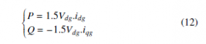
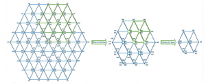
Figure 2: Decomposition of the five-level inverter vector diagram
We can therefore, through the imposition of reference currents, provide referencing for active power Pre f and reactive power Qre f fixed in zero that maintains a unity power factor (PF), we have:
This approach is founded on geometrically splitting of a vector diagram to several hexagons that represent low-level vector dia- grams, as shown in figure 2 [18].
To attain this objective, two actions need to be completed:
– Depending of voltage reference vector position Vre f , one of six – V is moving to center of the hexagon selected in the first action.
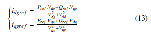
The DC link reference (Vdcre f ) is obtained by the PV P&O MPPT algorithm as shown in figure 1, corresponding to its maximum PV power output voltage at various irradiation levels. The regulation of DC bus voltage is performed by PI regulator and its output is considered as the active power component idgre f . The idgre f is given as,
![]()
With: Kp and Ki are the proportion and integral coefficients of DC-bus voltage controller PI, respectively.
- Generation of switching signals for VSI
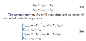
The idgre f and iqgre f are compared with idg and iqg, respectivly, to obtain the currents error and are given as,
Following these actions two times would reduce the five-level in- verter’s vector diagram to the two-level inverter’s vector diagram. Next, we will employ the classical method of vector modulation of the two-level inverter, discussed in the section 3.1.2.
4. Simulation results
For the hybrid system, a simulation model shown at figure 1 has been modulated with Matlab/Simulink R in order to validate and evaluate system performance. Simulation parameters are as shown in the appendix A. Penetration of wind and PV energy is studied under different weather conditions.As shown in Figure 3 and 4, the wind speed increases from 20 to 8, and finally drops to 5 m/s, at t= 0.3 and 0.7s, respectively. Solar irradiance level increases from 400 to 1000, than drops at 500, and increases to 300 W/m, at t= 0.3, 0.5, and 0.7s, respectively.
The three phase reference grid voltages (Vagre f , Vbgre f , Vcgre f ) are generated from Vdgre f and Vqgre f using inverse Parks transform.

Figure 3: Cp(λ,β)curves typical for different inclination angles
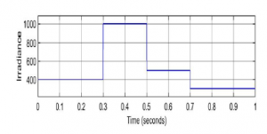
Figure 4: Ipv Vpv photovoltaic characteristics at different irradiation levels
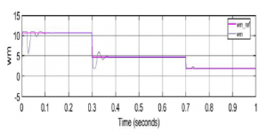
Figure 5: Generator rotation speed

Figure 6: DC-link voltage

Figure 7: wind power
Optimal Ωre f and Vdcre f are generated by Wind and PV MPPT P&O, respectively. As depicted in Figure 5 and 6, the corresponding variables are then regulated.
Under these conditions, Ωre f and Vdcre f are both refracted on the corresponding PV and wind powers, as shown at figures 7 and 8.
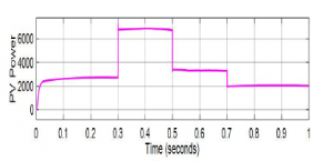
Figure 8: PV power
Three-phase grid voltages before filtering are shown in figure 9, representing five-level inverter output voltage waveform obtained from capacitors. Economically, it is not interesting to use a rectifier for each capacitor, so it is necessary to ensure the balance of the continuous bus, as depicted in Figure 10 .
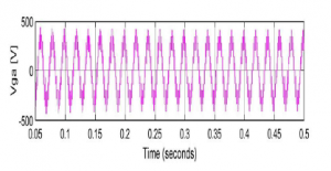
Figure 9: Output voltages of the three-phase inverter at five levels

Figure 10: Capacitor voltage
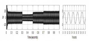
Figure 11: Grid current
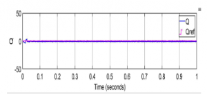
Figure 12: Reactive power

Figure 13: THD of grid currents injected
The AC current injected into grid is indicated in Figure 11. Dur- ing entire operating range, the reactive power is set to zero, then a unity PF is maintained, as shown in in Figure 12.
The figure 13 illustrates the THD currents injected in the grid. According to THD analysis above, the total harmonic distortion at Fc=1KHz given THD=0.80%. Therefore, as the number of levels is increased, THDs are minimized in comparison with classical multi-level inverters [19].
5. Conclusion
In this paper, the modeling and simulation of wind-power hybrid systems connected to the grid, using vector control systems were presented.A hybrid system based on wind and photovoltaic energy was set up with a five-level inverter. The VSRC’s purpose consists of extracting the maximum wind power, and the VSIC is respon- sible for extracting maximum PV power, and balance of dc-link capacitor in order to transfer produced power to utility-grid. This way, reactive power is fixed at zero, then a unity Power Factor PF is maintained. The proposed system has enhanced efficiency and reliability via a hybrid renewable energy system, the maximum power is extracted from independent MPPT using P&O algorithm, and reduces current THD. The results of the simulations showed the correspondence of the quantities assessed with the reference quantities and allowed the validation of the mathematical models.
- A. Demirbas, “Global Renewable Energy Projections,” Energy Sources, Part B: Economics, Planning, and Policy, 4(2), 212–224, 2009, doi:10.1080/ 15567240701620499.
- E. Oumaymah, O. Abdellah, E. A. Mustapha, “The Injection of Wind Power into a Grid Using a Multi-Level Inverter Controlled by SVPWM, booktitle= 2020 International Conference on Electrical and Information Technologies (ICEIT),” 1–6, IEEE, Rabat, Morocco, 2020, doi:10.1109/ICEIT48248.2020. 9113201.
- L. Wang, D. Zhang, J. Duan, J. Li, “Design and Research of High Voltage Power Conversion System for Space Solar Power Station,” in 2018 IEEE International Power Electronics and Application Conference and Exposition (PEAC), 1–5, IEEE, Shenzhen, 2018, doi:10.1109/PEAC.2018.8590543.
- F. Chishti, S. Murshid, B. Singh, “LMMN-Based Adaptive Control for Power Quality Improvement of Grid Intertie Wind–PV System,” IEEE Transactions on Industrial Informatics, 15(9), 4900–4912, 2019, doi:10.1109/TII.2019. 2897165.
- A. A. A. Radwan, Y. A.-R. I. Mohamed, “Grid-Connected Wind-Solar Cogen- eration Using Back-to-Back Voltage-Source Converters,” IEEE Transactions on Sustainable Energy, 11(1), 315–325, 2020, doi:10.1109/TSTE.2019.2890828.
- F. Chishti, S. Murshid, B. Singh, “An Intelligent Control for Synchronous Gen- erator Based Wind-PV-Battery Microgrid System,” in 2018 IEEE International Conference on Power Electronics, Drives and Energy Systems (PEDES), 1–6, IEEE, Chennai, India, 2018, doi:10.1109/PEDES.2018.8707685.
- B. Boukezata, Etude et commande d’une chaine de conversion d’e´nergie d’un syste`me solaire photovolta¨que, Thesis, Larbi Ben M’Hidi University, 2018.
- T. Kamal, M. Karabacak, S. Z. Hassan, H. Li, A. Arsalan, R. K. Rajkumar, “Integration and control of an off-grid hybrid wind/PV generation system for rural applications,” in 2017 International Conference on Innovations in Electrical Engineering and Computational Technologies (ICIEECT), 1–6, IEEE, 2017.
- S. Z. Hassan, H. Li, T. Kamal, M. Awais, “Stand-alone/grid-tied wind power system with battery/supercapacitor hybrid energy storage,” in 2015 International Conference on Emerging Technologies (ICET), 1–6, IEEE, 2015.
- R. S. S. Singh, M. Abbod, W. Balachandran, “A Design Scheme of Con- trol/Optimization System for Hybrid Solar — Wind and Battery Energy Stor- ages System,” in 2016 51st International Universities Power Engineering Conference (UPEC), 1–6, IEEE, Coimbra, 2016, doi:10.1109/UPEC.2016. 8114093.
- I. Elsayed, I. Nassar, F. Mostafa, “Optimization and Economic Evaluation of Small Scale Hybrid Solar/Wind Power for Remote Areas in Egypt,” in 2017 Nineteenth International Middle East Power Systems Conference (MEPCON), 25–30, IEEE, Cairo, 2017, doi:10.1109/MEPCON.2017.8301158.
- K. Saidi, M. Maamoun, M. Bounekhla, “Simulation and analysis of variable step size P&O MPPT algorithm for photovoltaic power control,” in 2017 In- ternational Conference on Green Energy Conversion Systems (GECS), 1–4, IEEE, Hammamet, Tunisia, 2017, doi:10.1109/GECS.2017.8066265.
- N. Kalaiarasi, S. S. Dash, S. Paramasivam, R. Bayindir, “Hybrid Cascaded Nine Level Inverter Using Dspace Controller for Standalone Photovoltaic Ap- plications,” in 2017 IEEE 6th International Conference on Renewable Energy Research and Applications (ICRERA), 745–750, IEEE, San Diego, CA, 2017, doi:10.1109/ICRERA.2017.8191159.
- B. S. N. Raj, R. Siddharth, S. M. Shyni, “MPPT with Bi-Directional DC-DC Converter and Multi-Level Inverter for Grid Connected Hybrid System,” in 2017 International Conference on Computation of Power, Energy Informa- tion and Commuincation (ICCPEIC), 773–777, IEEE, Melmaruvathur, 2017, doi:10.1109/ICCPEIC.2017.8290467.
- P. K. Hota, B. Panda, B. Panda, “Fault Analysis of Grid Connected Photovoltaic System,” American Journal of Electrical Power and Energy Systems, 5(4), 35, 2016, doi:10.11648/j.epes.20160504.12.
- A. Yazdani, P. Dash, “A Control Methodology and Characterization of Dy- namics for a Photovoltaic (PV) System Interfaced With a Distribution Net- work,” IEEE Transactions on Power Delivery, 24(3), 1538–1551, 2009, doi: 10.1109/TPWRD.2009.2016632.
- P. P. Dash, A. Yazdani, “A Mathematical Model and Performance Eval- uation for a Single-Stage Grid-Connected Photovoltaic (PV) System,” In- ternational Journal of Emerging Electric Power Systems, 9(6), 2008, doi: 10.2202/1553-779X.2033.
- A. Ghosh, F. Shahnia, “Applications of Power Electronic Devices in Dis- tribution Systems,” in J. A. Martinez-Velasco, editor, Transient Analysis of
Power Systems, 248–279, John Wiley & Sons, Ltd, Chichester, UK, 2014, doi:10.1002/9781118694190.ch7. - M. M. Irfan, P. H. K. Prasad, P. V. Rao, “Simulation of five-level five- phase SVPWM voltage source inverter,” in 2010 International Conference on Power, Control and Embedded Systems, 1–5, IEEE, Allahabad, 2010, doi: 10.1109/ICPCES.2010.5698659.
- K. Himour, K. Ghedamsi, E. M. Berkouk, “New alternative of design and con- trol of grid connected PV-Storage systems with the five level diode clamped inverter,” in 2013 Confe´rence Internationale des Energies Renouvelables (CIER’13), volume 2, 10, 2013.
- Yaosuo Xue, Liuchen Chang, “Closed-loop SPWM control for grid-connected buck-boost inverters,” in 2004 IEEE 35th Annual Power Electronics Specialists Conference (IEEE Cat. No.04CH37551), 3366–3371, IEEE, Aachen, Germany, 2004, doi:10.1109 5070.