An Enhanced Conceptual Security Model for Autonomous Vehicles

Adv. Sci. Technol. Eng. Syst. J. 5(6), 853–864 (2020);
 DOI: 10.25046/aj0506102
Connected and self-driving cars have emerged over the last decade as a leading example of cyber-physical systems, which seek to considerably enhance traffic safety, reduce emissions, decrease costs, and improve efficiency. Google, TESLA, Uber ATG are becoming pioneers in the autonomous vehicles industry. Autonomous vehicles can have a large codebase and with a large volume of messages exchanged. The concepts of connected driving, cooperative driving, and intelligent transportation systems increase the connectivity of vehicles to the internet or other cloud services. High connectivity, misconfiguration, and insecure coding widen the attack surface of autonomous vehicles. A conceptual model of autonomous vehicles is presented in this paper to better understand autonomous vehicles’ attack surface. In addition, specific threat modeling techniques are discussed. Experiments were carried out to demonstrate the security risks to autonomous vehicles due to third party Electronic Control Units.
1. Introduction
The term autonomous vehicles is used to designate technology- oriented vehicles with robotic and self-driving features (self-parking, GPS sensing tools, and higher automation capabilities). Both con- nected and self-driving cars have emerged over the last decade as a leading example of cyber-physical systems, which seek to enhance traffic safety, reduce emissions, decrease costs and improve effi- ciency. At the same time, the automobile industry has experienced a major transformation from monolithic manufacturing processes to distributed procurement. The paradigm of distributed procure- ment allows automobile manufacturers to acquire software and sensor/hardware components from numerous third parties.
Distributed systems usually comprise of a complex connec- tivity layer with different nodes. The features of connectivity in autonomous vehicles provide real-time connections to the web, sen- sors, radar, GPS with user privacy, and other measurement units [1, 2]. In other words, autonomous vehicles are empowered to ac- quire all relevant information needed to perform the self-driving functions [3].
As the market penetration of autonomous vehicles has increased, there is a growing demand among organizations, consumers, and regulatory bodies for the underlying technologies to be tested to guarantee their overall safety, as well as evaluate their cloud and
demand [4]. During the process of critical-information exchange between the vehicle and the external infrastructure, a new attack sur- face can emerge, as several stakeholders (telematics, hardware, and software components, etc.) and rapid modifications (i.e., software processes) are involved.
Sensors can provide an extensive amount of information on the environment surrounding the vehicle together with sensing the inter- nal components. Electronic Control Units (ECUs) and sensors are the focal point of information exchange inside autonomous vehicles, as they provide critical information to the engine control unit of the vehicle. The data obtained from sensors can be shared and utilized for all types of assessments and calculations by other automotive systems.
Sensors and ECUs contain a large codebase that was enhanced to provide features required by autonomous vehicles. This “func- tional abundance” has widened the attack surface, adding to the existing vulnerabilities that have not been identified in the old code bases. Sensors and ECUs can talk to each other with different net- works equipped in modern vehicles. The design of such networks has focused on efficiently wiring these components rather than on security.
There are 6 different levels of autonomous driving defined by the Society of Automotive Engineers as shown in Figure 1. Modern vehicles nowadays can achieve levels between two and three.
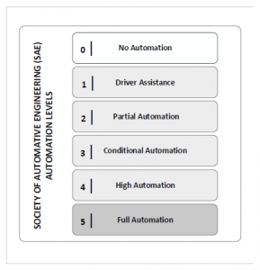
Figure 1: SAE automation levels
The motivation behind this work is to develop a conceptual model for autonomous vehicle to better understand the attack sur- face of autonomous vehicles and support their security testing. This will allow researchers and manufacturers to better understand the attack surface on autonomous vehicles and bridge the gap in the areas that have not been explored.
This paper develops on our previous work on defining a con- ceptual model for autonomous vehicles [5], where we modeled the autonomous vehicles’ assets, their vulnerabilities and the corre- sponding threats. Here, we take a closer look to modeling the assets related to the Controller Area Network (CAN) of the vehicles. The rationale behind this choice is that many aftermarket gadgets and smart applications taking advantage of the CAN bus could contain vulnerabilities exploitable by malware. We conduct an experiment on a simulated CAN bus to illustrate different security attack sce- narios such as traffic sniffing, replay attack and packet injection. Based on our experiment, we discuss and compare different threat modeling techniques that can be used to identify security threats based on the conceptual model presented.
The contribution of this article is, therefore: (i) enhanced con- ceptual model of autonomous vehicles to better understand their attack surface, (ii) analysis of Controller Area Network and cyber security attacks on modern vehicles, (iii) analysis of specific threat modeling techniques, (iv) demonstration of the cyber security risks to autonomous vehicles due to third party Electronic Control Units. The paper is organized as follows. In Section 2 we present an autonomous vehicle conceptual model. Section 3 describes Con- troller Area Network protocols. Section 4 overviews cyber security
attacks on modern vehicles. Section 5 focuses on a remote attack that had an impact on millions of vehicles. Section 6 provides an overview of different threat modeling techniques that could be used for threat modeling of autonomous vehicles. Section 7 illustrates the experimental results of sniffing and injecting traffic on CAN network using a simulated environment. In section 8 we summarize and discuss the future direction of research.
2. Autonomous Vehicle Conceptual Model
This section describes our enhanced conceptual model of au- tonomous vehicles [5]. The model consists of three main areas; vehicle, communications, and edge-cloud (Figure 2).
2.1 Vehicle
The vehicle component of the conceptual model focuses on the phys- ical boundary of the vehicle. In the conceptual model, we focused on the important items that will support future work in security mod- eling and analysis of autonomous vehicles. The main categories of the vehicle layer are Electronic Control Units (ECUs), they are the brain of the vehicle, Sensors, and Inter-Vehicle communication. In addition, it is important to highlight the internal connectivity items such as the On-Board Diagnostic port (OBD-II). Different types of networks exist in autonomous vehicles with different speeds. The ECUs in the vehicle are usually connected to at least one or more internal vehicle network. The gateway is used to facilitate com- munication between different communication buses. The OBD-II connection provides access to the vehicle’s internal network and interaction with various low-level sensors.
ECUs are essential components of modern vehicles. Each ECU is responsible for performing actions such as door locks, power steering, fuel injection, and many other critical functions. ECUs can also be categorized into subcategories based on their functionality [6]. The list below provides categories for ECUs found in modern vehicles:
Powertrain: controls many factors in vehicles and responsi- ble for transmission, emission controls, and onboard control modules.
Safety: vehicle safety-related operations such as collision detection, active parking, and air-bag system.
Body: less critical operations of the vehicle such as power windows and mirrors, cooling and heating, etc.
Examples of some of the key ECUs from the categories above are:
- ECM: engine control module
- VVS: vehicle vision system
- IRM: inflatable restrain module
- NCM: navigation control module
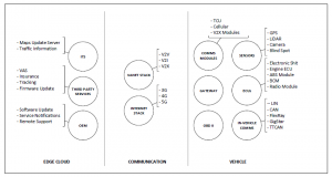
Figure 2: Autonomous Vehicle Conceptual Model
Sensors are used in autonomous vehicles to collect informa- tion about the vehicle’s surroundings. Vehicles are equipped with various sensors, examples of sensors equipped are GPS, cameras, LiDAR. The vehicle uses the information received from the sensors to perform different actions such as warning messages, navigation capability, distance calculation, and others.
The Inter-vehicle communication component of the concep- tual model focuses on the communication networks in the physical boundary of the vehicle. The main purpose of these networks is to allow efficient communication between electronic units in the vehicle. There are different types of networks in vehicles such as CAN, TTCAN, FlexRay, and Local Interconnect Network (LIN) [7, 8]. The CAN is widely used in automotive to support critical applications with a bandwidth of 125 kBits/s. The LIN bus runs at a lower bandwidth (10 kBit/s) to support less critical applications such as power windows and doors lock. FlexRay is a more expensive implementation of CAN, used commonly in BMW. FlexRay has 2 channels at a speed of 5 and 10 Mbit/s [9, 10].
2.2 Communication
The communication layer of the model focuses on the external communication medium for autonomous vehicles. Future trans- portation system is envisioned to support cooperative driving and information exchanging to enhance the driving experience, increase safety, and reduce collisions. There are two main categories in the communication layer; VANET stack and Internet Stack.
VANET Stack is the vehicular Ad Hoc Networks (VANETs). VANETs can use wireless networking technology to allow vehi- cles to communicate with each other and share information using
Dedicated Short Range Communication (DSRC). There are dif- ferent types of communication in VANETs. The first one is V2V, which stands for Vehicle to Vehicle communication. V2I: vehicle to station communication. V2R: vehicle to Road Side Unit (RSU) communication. V2X: vehicle to everything.
There are two types of messages in VANETs; beacon messages and special purpose messages [11, 12]. Vehicles broadcast mes- sages that act as heartbeats using beacon messages. Special purpose messages carry information about collisions and warning messages to nearby vehicles [13]. VANETs using DSRC or even cellular net- work is anticipated as the future of intelligent transportation system [14].
Internet Stack component of the model considers the cellular net- work as the communication means. Internet stack includes 4G and 5G data link and physical link [15]. Initial research in autonomous driving focused on VANETs as the future of communication for vehicles using DSRC. Modern vehicles are equipped with cellular network connectivity that could enable VANET communication over cellular network.
2.3 Edge Cloud
Edge Cloud layer of the model focuses on the vehicle communi- cation with external entities. Original Equipment Manufacturers (OEM) perform remote updates to vehicles remotely for applying patches, issues fix or enhance features. Many services are currently offered by third party providers such as media services, fleet man- agement, vehicle tracking, and many other applications and services. Below are some examples:
- Maps update
- Traffic
- OEM firmware
- Third-party dongles firmware
- Value Added
Some insurance companies nowadays mandate drivers to install OBD-II compatible dongles to monitor driving behavior and adjust insurance tariffs accordingly. Vehicles are expected to be connected to edge cloud services to support smart and green transportation [16]. As part of intelligent transportation system management [17, 18], vehicles are expected to be connected to transportation authorities and share various types of information.
3. Overview of Controller Area Network
The Controller Area Network (CAN) is a standardized network adopted by many car manufacturers for efficiency, safety, and manu- facturing purposes. CAN ensures minimum latency, together with other features to handle functional networks of a vehicle. It has been adopted since early 1980s to primarily handle automotive elec- tronics, and more specifically, different types of electronic control units [19]. The CAN protocol has many distinctive features such as being able to discover defects in the communication network and electronic control units (ECUs) [20]. ECUs play a crucial role in operating an autonomous vehicle. By allowing ECUs to exchange information via CAN, the autonomous vehicle can support new intel- ligent features. In comparison with other networks, however, CAN have some weaknesses such as limited electrical loading, and vulner- ability to overflow of undesirable interactions or communications [21].
Known vulnerabilities of CANs have encouraged experts to develop a new security network for ECUs, especially for auto- mated and self-driving vehicles [20]. One of the major motives for developing a new network is that CAN was not designed for communications from outside the vehicle, i.e. vehicle-to-Internet communications, vehicle-to-cloud, vehicle-to-pedestrian, and other types of connectivity. As a result, cyber security challenges, particu- larly denial-of-service attacks are a major hurdle when using CAN for autonomous vehicles. Moreover, third party dongles have been introduced by different service providers such as insurance or fleet management companies. These devices interface with the vehicle through the On-Board Diagnostics port (OBD-II). Physical OBD-II connection provides access to the vehicle’s internal network and interaction with various low-level sensors.
3.1 CAN Protocols
CAN is a simple protocol that was deployed vehicles since 1996. It allows Electronic Control Units (ECUs) to communicate with each other. CAN run on two wires; CAN High (CANH) and CAN Low (CANL). At the physical layer, CANH uses differential signaling, which is used in environments where fault-tolerance to noise is a must. When a signal comes in, CANH raises the voltage on one line and drops the other line of an equal amount.
- The OBD-II Connector
Most vehicles are equipped with On-Board Diagnostic Connector named OBD-II. It is usually located under the steering wheel of a vehicle. It is also known as a diagnostic link connector (DLC). CAN Connections can be found in supported vehicles from the OBD port in dual-wire pairs. CANH and CANL can be found on pin 6 and 14 or the OBD-II connector.
- CANH: High-Speed CAN Lines
CANL: Low Speed or Mid Speed CAN Lines (LS-CAN and MS-CAN).
- CAN Packets Layout
There are two types of CAN packets; standard and extended. Ex- tended packets are like the standard ones but with larger space to hold IDs. The Complete frame of standard CAN is shown in Figure
- Fields of standard packets are described
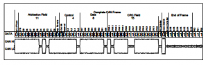
Figure 3: CAN Frame of standard packet [22]
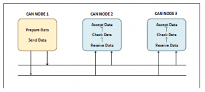
Figure 4: CAN communication based on broadcast messages
Arbitration ID: a broadcast message that identifies the ID of the target device it tries to communicate with.
- Identifier Extension (IDE): always 0 for standard CAN
Data length code (DLC): the size of the data, which ranges from 0 to 8 bytes
- Data: data to be
Communication on CAN bus is broadcast messages, similar to UDP packets on ethernet networks as shown in Figure 4. All controllers see every packet transmitted on CAN. Extended packets are similar to standard packets, but the can be changed together to create longer IDs. They are designed to fit inside standard CAN packets with backward compatibility.
- The ISO-TP Protocol
The ISO 15765-2 is a standard for sending packets over CAN. It extends the limit of sending 8 bytes to 4095 bytes. This protocol is commonly used for diagnostic messages (Unified Diagnostic Ser- vices) and KWP messages (alternative protocol to CAN). The first byte is used for extended addressing, leaving only 7 bytes for data per packet. Using ISO-TP can easily flood the CAN bus, thus it should be used carefully [23].
- The Local Interconnect Network Protocol
The Local Interconnect Network (LIN) is a master-slave facility that was designed to complement CAN. It can have up to 16 slaves
4. Overview of Cyber Attacks on Modern Vehicles
This section focuses on recent cyber security attacks on modern vehicles. Firstly, the section provides an overview of the interesting vulnerabilities discovered by researchers in different modern vehi- cles. In the second part of this section discusses in detail one of the most interesting attacks on vehicles, the Jeep Cherokee 2015 attack.
4.1 Vulnerabilities Overview
- Jeep Cherokee
Uconnect is an entertainment system that relies on cellular network to deliver entertainment services and applications in Jeep Cherokee entertainment system [24]. The entertainment system had a diagnos- tic bus port that runs on 6667. Since the port had no authentication requirements, some sensitive information was obtained by connect- ing to the port, such as GPS information, VIN, and other private information. At the time of the research, around 1.4 million vehicles using the Uconnect system were vulnerable. To identify vulnerable vehicles, a mass scan for the diagnostic bus port could be per- formed on the IP range of the service provider. The researchers used Sprint Cellular Network IP ranges to identify vulnerable vehicles on 21.0.0.0/8 and 25.0.0.0/8 address ranges. Additional details on the sequence of execution from Uconnect system to cyber-physical actions are explained in next section.
- GM Chevy Impala
Another entertainment system related vulnerability was discovered in the GM Chevy Impala by researchers at the University of Califor- nia at San Diego and the University of Washington [25]. This time, the entertainment system had a buffer overflow vulnerability. The vulnerability was exploited by playing a specially crafted mp3 file in the in-car call system. Successfully exploiting the vulnerability allows an attacker to access the vehicle’s system and control most of its critical functions.
- BMW
Security researchers identified a vulnerability in BMW Connected- Drive service to unlock the vehicle remotely. Confidentiality re-
quirement was missing in the communication between the vehicle and the BMW server for ConnectedDrive, the communication was not encrypted. Due to this, the attack performed using a fake cellular network and spoofed the BMW server. The vehicle is equipped with a communication capability using a pre-installed SIM card. An unlock message was sent to the vehicle using the spoofed server and it unlocked the vehicle successfully [26]. At the time, over 2.2 million vehicles were affected by the vulnerability. BMW released a security patch to fix the vulnerability by adding encryption to the communication between the vehicle and the BMW server.
- Corvette
Corvette attack was mainly an attack on a third-party device, specif- ically on an insurance dongle connected to the vehicle via OBD port. The insurance dongle was installed to track driver behavior to determine insurance tariffs. The impact of the vulnerability de- pends on the commands allowed via OBD port. In the case of the Corvette, the researchers were able to trigger cyber-physical actions on the vehicle via the connected dongle. Through exploiting the vulnerability, the researchers were able to send an SMS to remotely apply breaks on the vehicle. Depending on the commands allowed from the OBD, other vehicles the attack could result in controlling more critical functions [27].
- Tesla S Model
Different attackers were performed in Testa S Model, some required physical access to the vehicle and others exploited remotely. For the physical access, researchers were able to connect a laptop to the vehicle’s in-car entertainment system and identified multiple vulner- abilities. Researchers were able to successfully implant a trojan in the vehicle’s system to control it remotely. All the vulnerabilities identified in the research were patched by Tesla [28].
- Nissan LEAF
Nissan application named Companion Application is used to allow users to have access to some information on the vehicle and perform specific actions. Researchers were able to identify vulnerabilities in the Companion Application and gain access to the historical GPS information of the vehicle [29].
5. Analysis of Cyber Security Attack on JEEP Cherokee
In this section, we analyze the attack on Jeep Cherokee that affected over 1.4 million vehicles. The researchers were able to perform the cyber attack remotely, with no physical access to the vehicle. Initial research required reverse engineering some of the components of the vehicle to plan the attack and chain different stages of the attack to reach from remote exploitation to perform physical actions on the vehicle such as applying breaks, vehicle’s steering, and others. Although the experiment was conducted on Jeep Cherokee, it was not limited to this model. Vehicles with the same entertainment unit may have suffered similar vulnerabilities and impacts. In research, the attack surface was analyzed and the feasible attack chain was chosen to perform the full attack chain, from initial access to physi- cal action execution. The first part of this section discusses the CAN connectivity architecture seen in Jeep Cherokee, then discusses the attack phases. This is important to understand how to send messages between two networks in the vehicles (CAN buses).
5.1 CAN Connectivity
In the example of Jeep Cherokee, two CAN buses are used; CAN- HIS and CAN-C connected to different networks. ECUs talk to each other via CAN bus, each CAN bus is connected to a different set of ECUs. The CAN buses of Jeep Cherokee are explained below. The first CAN bus in the vehicle is CAN-IHS, stands for Controller Area Network for Interior High Speed. The CAN-IHS bus is low speed CAN bus that is used for non-critical systems such as climate controls, radios, and others. Examples of the ECUs connected to CAN-IHS bus are as follow:
- AMP Ampilifer Radio
- Body Control Module (BCM).
- AHLM Module – Headlamp
- PAM Module – Park
- DLC Data Link Connector
The second CAN bus is CAN-C bus, which is high-speed bus that is responsible to connect critical ECUs. Examples of the ECUs connected to CAN-C bus is as follow:
- Anti-Lock Brakes Module (ABS)
- Body Control Module (BCM)
- RADIO Module
- Electronic Parking Brake –
- Electronic Power Steering –
As we can see in the examples above, some ECUs are connected to both CAN buses, two examples are the radio module and the BCM Module. The direction the researchers took in the research was to target an ECU unit that could talk to both networks to widen the impact of the attack and reach critical ECUs.
5.2 Attack Phases
The attack chain developed by the researchers started from remote device exploitation to execute commands and sending control sig- nals to critical ECUs. In section, the analysis is divided into four phases; target identification, remote code execution, sending CAN messages, and CAN payloads.
- Identify Target
Initially, the researchers identified D-Bus service port 6667 by scan- ning the vehicle internally; connecting to the in vehicle’s WiFi network. After examining the networking configurations of Ucon- nect, the researchers discovered an additional interface with a public IP address, which could result in remote exploitation of Uconnect system. To identify vulnerable Uconnect systems, performing a scan on port 6667 over the provider network. It was initially as- sumed that the provider blocks connections from other providers. The researchers took an additional step by exploiting a femtocell from the same provider to ensure that traffic is not blocked. It was later discovered that the port is open to all providers which increases the impact of the vulnerability. To avoid false positives, the service error message of services determines if the port belongs to Uconnect system or any other service such as IRC (Internet Relay Chat).
- Gain Remote Code Execution
The researchers found more than one way to gain remote execution on the target system via the D-Bus service of Uconnect. Different vulnerabilities identified for remote code execution on the D-Bus service in addition to a feature that was implemented on the D- Bus service to allow code execution for an unauthenticated user. The first vulnerability idenfied was due to unsanitized user input on navTrailService function. The other vulnerabilities are either unauthenticated execution or command injection vulnerabilities.
Since arbitrary command execution achieved using the D-Bus service, researchers developed different payloads to interact with the CAN bus and obtain information using LUA scripts. Examples of the crafted commands sent via the D-Bus service.
Uconnect system: From the Uconnect system, GPS coordi- nates can be queried.
HVAC Module (A/C Heater): controlling heating and A/C of the vehicle.
- Radio Volume: controlling the volume of the
Knobs: disabling the D-Bus service make knobs unavailable and unresponsive.
- Sending CAN Messages
The code execution achieved through the D-Bus service is performed on the OMAP chip. Although the Uconnect system is connected to both CAN buses of the vehicle; CAN-IHS and CAN-C, it can- not send messages to CAN directly. The communication from the OMAP to CAN buses are handled by Renesas V850ES/FJ3 chip. The researchers updated the V850 chip from the OMAP with a mod- ified firmware to be able to send CAN messages. At this point, the execution from OMAP uses V850 chip as a proxy to communicate with CAN buses.
- CAN Messages Payloads
The communication between OMAP chip and V850 chip uses a Serial Peripheral Interface (SPI). The V850 chip originally had a predefined set of command IDs with hardcoded data to commu- nicate with CAN bus. With flushed firmware, the V850 can send arbitrary CAN data from the OMAP chip.
At this point, arbitrary CAN commands can be sent remotely via the D-Bus service. After identifying the messages triggering cyber-physical actions, researchers were able to perform turn sig- nals, locks, RPMS. These messages are considered normal CAN messages, the diagnostic CAN messages could cause greater cyber- physical impact but requires the vehicle to be traveling at a low speed.
6. Analysis of threat modeling frameworks
Threat modeling is in important phase of security engineering pro- cess. It involves identifying all security threats to the system regard- less of the possibility to exploit them. It requires good understanding of the system. In order to develop meaningful security requirements, it is essential to have threats identified. Proper identification of threats in early stages can greatly reduce the ability of misusing the system [30]. There are different techniques of threat modeling [31]. In general, some of the main threat model techniques are:
- Attacker-centric
- Asset-centric
- Software-centric
These models are general and not specific to autonomous vehicles.
6.1 Attacker-centric approach
This threat modeling technique is built on attacker perspective by profiling an attacker’s characteristics, goals and motivation to ex- ploit vulnerabilities. The modeling technique aims to understand potential attackers who are likely to target the system and type of attacks that might be executed. Based on the understanding, mitigation strategies can be developed against studied attackers.
This approach uses tree diagrams for threat modeling. Examples of key elements of this approach include: the goals of the attacker, the techniques used by the attacker, the system components includ- ing software and assets and means of detection and mitigation.
A simple example is an attacker trying to obtain data from a database that is hosted in a backend system accessible from a web- site. Using this approach, the goal of the attacker would be to obtain the information stored in the database. Techniques include SQL injection (using unsensitized input commands) on the website, and use of automated tools by which exploitation could be carried out.
- Intel’s TARA (Threat Agent Risk Assessment)
This threat modeling technique focuses on prioritizing the most critical areas of the system and most vulnerable to attacks [32]. This ensures that the threat modeling efficiently address the areas that are exposed the most. Moreover, the framework focuses on threat agents that are most dangerous, what techniques and tradecrafts used to achieved their goals. The most exposed areas are then deter- mined by cross-referencing the information obtained with known
vulnerabilities. The process is shown in Figure 5. TARA’s goal is to build security strategies with focus on areas with highest level of risk. This is achieved by determining the most likely attack vectors and applying efficient security strategy to address them. TARA relies on three main components:
Common Exposure Library (CEL): list of known vulnerabili- ties and exposures.Threat Agents Library (TAL): unique library containing 22 threat agent and nine threat agent attributes.
Methods and Objectives Library (MOL): contains threat agent objectives and methods used to achieve goals and objectives.
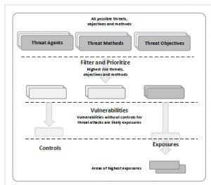
Figure 5: Narrowing down the fields of attacks.
- Cyber Kill Chain
The Cyber-Kill threat modeling approach was developed by Lock- heed Martin, an American company focusing on global aerospace, defense, security and advanced technologies [33]. The method fo- cuses on the steps taken by an attacker to achieve desired goal. As name implies, the method is chained into multiple phases, each phase has its associated set of goals. Each phase outcomes con- tribute to the next phase. The cyber kill chain contains the following steps:
Reconnaissance: research, identification, and selection of targets
Weaponization: Combining remote access malware with ex- ploit into deliverable payload
- Delivery: Delivering a payload to target (weaponized exploit).
Exploitation: Exploit vulnerable application or system upon delivery
Installation: Persistent access via means of installing back- door in exploited system.
Command and Control: Outside server communicates with the weapons providing ”hands on keyboard access” inside the target’s network
6.2 Asset-centric approach
This approach has two main components; assets and threats. The assets taxonomy involves identifying assets, asset groups, asset types, asset details [34]. The threat taxonomy utilizes attack trees, attack graphs and assets’ own failure modes in order to prioritize
and vulnerabilities associated with information assets. The OC- TAVE Allegro method consists of four different phases, with total of eight steps as shown in Figure 6.
- Phase 1: risk measurement criteria development
Phase 2: identification and profiling of assets then the identi- fication of containers to the identified assets
Phase 3: threats to identified containers are identified with respect to assets
- Phase 4: mitigation strategies
associated risk levels and then mapped to assets. Methodologies
based on the asset-centric approach include PASTA, OCTAVE and STRIDE
- PASTA
PASTA (Process for Attack Simulation and Threat Analysis) is an asset-centric approach to threat modeling [34]. This methodology was developed by Minded Security and VerSprite. The obvious advantage of this methodology that it providers valuable informa- tion about risk reduction and security strategy that could target non-technical staff (example management or stakeholders). The methodology involves seven different stages illustrated below.
- Stage 1: Define Objectives
- Stage 2: Define Technical Scope
- Stage 3: Application Decomposition
- Stage 4: Threat Analysis
- Stage 5: Weaknesses and Vulnerability Analysis
- Stage 6: Attack Modeling and Simulation
- Stage 7: Risk Analysis and Management The main goals of PASTA methodology are:
- Allows cost and time savings
- Integrates with SDLC
- Better understanding of most likely attack sources
Better communication between security groups inside the company
- Increases the maturity of the organization in security
- OCTAVE
OCTAVE Allegro (Operationally Critical Threat, Asset and Vul- nerability Evaluation) a method developed by CERT Survivable Enterprise Management team. This method focuses information assets security in respect to the well-known security requirements, which are Confidentiality, Integrity and Availability (CIA). This method investigates the ways information assets are stored, trans- ferred, used and processed. In addition, it extends to cover threats

Figure 6: Phases and steps of OCTAVE Allegro.
- STRIDE
The acronym STRIDE stands for six categories of security risks: Spoofing, Tampering, Repudiation, Information Disclosure, Denial of Service, and Elevation of Privileges.
Spoofing refers to the act of posing as someone else (i.e. spoofing a user) or claiming a false identity (i.e. spoofing a process). Spoofing threats affect the authenticity property.
Tampering refers to malicious modification of data in tran- sit, at rest, or within processes. Tampering threats affect the integrity property.
Repudiation refers to the ability of denying that an action or an event has occurred. Repudiation threats affect the non- repudiation property.
Information Disclosure refers to data leaks or data breaches. Disclosure threats affect the confidentiality property.
Denial of Service (DOS) refers to causing a service or a net- work resource to be unavailable to its intended users. DOS threats affect the availability property
Elevation of Privileges (EP) refers to gaining access that one should not have. EP threats affect the availability property
By considering these risks for each asset, STRIDE threat model allows to list the applicable risks (also called failure modes) to each asset, and to map them to threats and known attacks. This way mea- sures can be identified to examine and address gaps in the security posture of applications.
7. Experimental Results
This section of the paper discusses and analyzes a proof of concept of two replay attack and packet injection on a simulated CAN bus. In this experiment, we setup a simulation environment to simulate random CAN traffic generation and identifying control signals to perform specific physical actions.
7.1 Simulation Environment Setup
The simulation environment is setup using a virtual CAN bus than communicated over TCP and other tools that interact with the virtual CAN bus. In this section, we described the tools used to set up the simulation environment.
CAN for vehicle communication have different drivers and soft- ware utilities with no unified CAN tools and interfaces. However, there is a set of tools with a common interface available in Linux. The SocketCAN is an interface that was created on the Open Source development site BerliOS in 2006. By extending the Berkeley socket API in Linux, SocketCAN can send and receive traffic from the CAN controller in the model of a network device.
SocketCAN is not limited to physical CAN devices and net- works, it supports built-in CAN chips and card drivers, external communication via serial or USB, and virtual CAN devices. More importantly, it supports virtual CAN environments.
- Atmel AT91SAM SoCs
- Bosch CC770
- ESD CAN-PCI/331 cards
- Freescale FlexCAN
- Freescale MPC52xx SoCs (MSCAN)
- Intel AN82527
- Microchip MCP251x
- NXP (Philips) SJA1000
Figure 7 compares the implementation of traditional CAN soft- ware with the SocketCAN implementation, which is unified. In traditional CAN software, the application has its protocols stack that talks to a character device, whereas SocketCAN is implemented in the Linux kernel with its own CAN protocol family enabling applications to communicate with a CAN bus interface in a generic network interface fashion.
SocketCAN repository contains various utilities for Linux CAN subsystem. These utilities can work with CAN communications within the vehicle from Linux operating system. Examples of the functions supported by the suite:
- Basic tools to display, record, generate can traffic
- Tools to send, generate, sniff CAN
- Serial line discipline (SLC) configuration
- Log files converters
- CAN access via IP sockets
- CAN bus management

Figure 7: SocketCAN compared to traditional CAN software
Different tools are used in the experiment For CAN bus diagno- sis, monitoring, and simulating target vehicle that interacts with the virtual CAN. For CAN diagnostic and monitoring, Kayak applica- tion is used. Kayak is a Java-based that can read CAN traffic log files and display information graphically on gadgets.
For target vehicle simulation and CAN traffic fuzzing, the instru- ment cluster simulator (ICSim) is used, which is an opensource tool developed by Open Garages. The ICSim software is Linux based and relies on virtual CAN devices. ICSim was designed to allow researchers, individuals, developers and others to safely familiarize themselves with CAN reversing. ICSim includes a graphical inter- face for some of the functions of CAN such as doors, engine RPM, and others.
7.2 Security Attacks on CAN Bus
The following experiment shows how the virtual environment setup can generate, display, and sniff CAN frames. Using the libraries and utilities described earlier in this section, a virtual CAN interface was created in Linux (Debian 4.19-28).
Using the virtual CAN interface is running as “vcan0”, CAN frames can be sent and received using can-utils suite. The current messages are random CAN messages, which are not currently an- alyzed as per their functions or character device they are trying to communicate with. The first step is generating random CAN mes- sages with default bi trate. The messages generated can be viewed in Figure 8.
Since the messages are communicated over TCP/IP in the virtual environment, messages can be sniffed using different tools such as Wireshark and CANSniffer or Kayak.
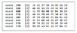
Figure 8: CAN frames dump using candump of can-utils
7.3 Injecting CAN Frames
This part explains injecting CAN frames into the virtual CAN bus and displays results in the simulator. To identify the CAN message responsible to perform a physical action, the ICSim was used to generate specific actions on the vehicle, and the generated CAN traffic was recorded. Then simply replaying the recorded messages could identify the messages related to the performed actions with other noise that can be discarded for this experiment. The sequence followed in the experiment is explained in Figure 9.

Figure 9: Sequence used to identify CAN messages
Using the generated traffic from the libraries explained earlier, the signals used to perform physical actions were identified. CAN traffic was generated on virtual CAN and recorded in log files. The signals responsible for door locks, RPM and signals identified as shown in Figure 10. At this point, using the CAN ID, we can send specific CAN messages to trigger doors, acceleration or light sig- nals. For example, to accelerate, the CAN ID used is 244 (hex representation).
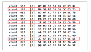
Figure 10: Specific CAN messages for desired functions
After identifying the CAN messages to perform specific phys- ical actions, two security attacks are performed. The first one is a replay attack. This was achieved by recording CAN traffic in a file. Since CAN communication (in the scenario described in the paper) does not use session IDs or encryption to protect against replay attacks, traffic was recorded were played on a different virtual CAN bus successfully. The second security attack performed is traffic injection. In a virtual CAN bus with random traffic being communi- cated, specific commands were sent to set RPM to a specific value, open doors, and start turn signals. The results of the signals sent are shown in Figure 11.
The tools used in the experiment do not simulate actual ECUs in terms of behavior. Some ECUs are wired directly and do not accept messages from the CAN bus directly. In such situations, additional effort is required to send signals from allowed ECUs. In diagnostic mode, messages might be accepted from the CAN bus. Additional research is required to fully understand what can be controlled directly from the CAN bus. Aftermarket ECUs expose CAN connectivity and expand the attack surface of modern vehi- cles. In the experiment, we focused on simple scenarios of packet sniffing and packet injection. The CAN bus is designed to allow real-time communication between ECUs but it is not secured by design. These types of attacks are not limited to aftermarket ECUs or gadgets, any successful exploitation or code execution on ECU connect to CAN bus could achieve similar or higher impact.
In the presence of aftermarket devices, new range of vulnera- bilities will be introduced. The inter-vehicle communication was not designed to interact outside the perimeter of the vehicle. With the absence of defined threats, it is extremely difficult to provide assurance on security measures taken.
Starting from a conceptual model for autonomous vehicles is essential to capture different components of autonomous driving ecosystem. Threat modeling could be applied to identify potential threats pertaining autonomous vehicles and support the development of security requirements that cover scenarios discussed in this paper. This should support addressing the knowledge gap in the field of autonomous vehicle security.
Our future plans include the research of a test-based security verification framework for autonomous vehicles. Due to the lack of a centralized tests repository for security testing, we will focus on developing a security test-cases repository based on blockchain technology. In addition, the current research was limited to few

Figure 11: Results of the physical actions displayed on ICS Simulator
scenarios on attacks on CAN bus. We plan to design more attack scenarios against common vulnerabilities in aftermarket ECUs.
8. Conclusion
Several technologies in modern vehicles were designed and built without security in mind. As modern vehicles and future au- tonomous vehicles are becoming more and more computerized and connected, these technologies present new risks and widen the attack surface.
Threat modeling is an essential step for defining security require- ments of autonomous vehicles, or any system in that regard. With the absence of defined threats, it is extremely difficult to provide assurance on security measures taken. The initial work conducted to- wards the research was focused on establishing a conceptual model for autonomous vehicles. This will support in defining the scope and basing the threat model against it.
The experiment showed briefly how easily CAN traffic can be captured or sniffed. In the presence of aftermarket devices, new range of vulnerabilities will be introduced. The inter-vehicle com- munication was not designed to interact outside the perimeter of the vehicle. However, these devices open new attack surfaces allowing some components of inter-vehicle communication to be exposed to the outside world.
Conflict of Interest
The authors declare no conflict of interest.
Acknowledgment
This work was supported by the Center for Cyber-Physical Systems, Khalifa University, under Grant 8474000137-RC1-C2PS-T3.
- A. S. Gajparia, C. J. Mitchell, C. Y. Yeun, “Supporting user privacy in location based services,” IEICE transactions on communications, 88(7), 2837–2847, 2005, doi:10.1093/ietcom/e88-b.7.2837.
- D. M. Konidala, C. Y. Yeun, K. Kim, “A secure and privacy enhanced protocol for location-based services in ubiquitous society,” in IEEE Global Telecommu- nications Conference, 2004. GLOBECOM’04., volume 4, 2164–2168, IEEE, 2004, doi:10.1109/GLOCOM.2004.1378393.
- A. Talebpour, H. S. Mahmassani, “Influence of connected and autonomous vehicles on traffic flow stability and throughput,” Transportation Research Part C: Emerging Technologies, 71, 143–163, 2016, doi:10.1016/j.trc.2016.07.007.
- B. Sheehan, F. Murphy, M. Mullins, C. Ryan, “Connected and autonomous vehicles: A cyber-risk classification framework,” Transportation research part A: policy and practice, 124, 523–536, 2019, doi:10.1016/j.tra.2018.06.033.
- A. O. Al Zaabi, C. Y. Yeun, E. Damiani, “Autonomous Vehicle Security: Conceptual Model,” in 2019 IEEE Transportation Electrification Confer- ence and Expo, Asia-Pacific (ITEC Asia-Pacific), 1–5, IEEE, 2019, doi: 10.1109/ITEC-AP.2019.8903691.
- A. M. Wyglinski, X. Huang, T. Padir, L. Lai, T. R. Eisenbarth, K. Venkatasub- ramanian, “Security of autonomous systems employing embedded computing and sensors,” IEEE micro, 33(1), 80–86, 2013, doi:10.1109/MM.2013.18.
- “L. S. P. Revision,” 2016.
- C. P. Szydlowski, “CAN specification 2.0: Protocol and implementations,” Technical report, SAE Technical Paper, 1992, doi:10.4271/921603.
- S. C. Talbot, S. Ren, “Comparision of fieldbus systems can, ttcan, flexray and lin in passenger vehicles,” in 2009 29th IEEE International Conference on Distributed Computing Systems Workshops, 26–31, IEEE, 2009, doi: 10.1109/ICDCSW.2009.15.
- M. Wolf, A. Weimerskirch, C. Paar, “Secure in-vehicle communication,” in Em- bedded Security in Cars, 95–109, Springer, 2006, doi:10.1007/3-540-28428-1 6.
- L. Buttya´n, T. Holczer, I. Vajda, “On the effectiveness of changing pseudonyms to provide location privacy in VANETs,” in European Workshop on Se- curity in Ad-hoc and Sensor Networks, 129–141, Springer, 2007, doi: 10.1007/978-3-540-73275-4 10.
- M. Raya, J.-P. Hubaux, “The security of vehicular ad hoc networks,” in Pro- ceedings of the 3rd ACM workshop on Security of ad hoc and sensor networks, 11–21, 2005, doi:10.1145/1102219.1102223.
- P. Papadimitratos, L. Buttyan, T. Holczer, E. Schoch, J. Freudiger, M. Raya,
Z. Ma, F. Kargl, A. Kung, J.-P. Hubaux, “Secure vehicular communication systems: design and architecture,” IEEE Communications Magazine, 46(11), 100–109, 2008, doi:10.1109/MCOM.2008.4689252. - L. Bariah, D. Shehada, E. Salahat, C. Y. Yeun, “Recent advances in VANET security: a survey,” in 2015 IEEE 82nd Vehicular Technology Conference (VTC2015-Fall), 1–7, IEEE, 2015, doi:10.1109/VTCFall.2015.7391111.
- H. Seo, K.-D. Lee, S. Yasukawa, Y. Peng, P. Sartori, “LTE evolution for vehicle- to-everything services,” IEEE communications magazine, 54(6), 22–28, 2016, doi:10.1109/MCOM.2016.7497762.
- C. C. Forecast, “Global connected car market to grow threefold within five years,” GSMA Connected Living Programme: mAutomotive, 2013.
- N. Lu, N. Cheng, N. Zhang, X. Shen, J. W. Mark, “Connected vehicles: So- lutions and challenges,” IEEE internet of things journal, 1(4), 289–299, 2014, doi:10.1109/JIOT.2014.2327587.
- N. Liu, “Internet of Vehicles: Your next connection,” Huawei WinWin, 11, 23–28, 2011.
- A. K. Singh, A. Negi, S. Azad, S. Mudali, “Fuzzy based controller for lidar sensor of an autonomous vehicle,” Energy Procedia, 117, 1160–1164, 2017, doi:10.1016/j.egypro.2017.05.241.
- D. Fe´nyes, B. Ne´meth, P. Ga´spa´r, “A predictive control for autonomous ve- hicles using big data analysis,” IFAC-PapersOnLine, 52(5), 191–196, 2019, doi:10.1016/j.ifacol.2019.09.031.
- D. J. Fagnant, K. Kockelman, “Preparing a nation for autonomous vehicles: opportunities, barriers and policy recommendations,” Transportation Research Part A: Policy and Practice, 77, 167–181, 2015, doi:10.1016/j.tra.2015.04.003.
- C. Smith, The car hacker’s handbook: a guide for the penetration tester, no starch press, 2016, doi:10.4271/1593277032.
- I. Foster, K. Koscher, “Exploring controller area networks,” login. USENIX Association, 40(6), 2015.
- C. Miller, C. Valasek, “Remote exploitation of an unaltered passenger vehicle,” Black Hat USA, 2015, 91, 2015.
- A. Greenberg, “GM took 5 Years to fix a full-takeover hack in millions of Onstar cars,” Wired, September, 1059–1028, 2015.
- “J. Banter, ”Open Thyself! – Security vulnerabilities in BMW’s Connected- Drive,” C’T Magazine for Computer Technique,” 2020.
- “A. Charlton, ”Hackers disable Corvette brakes by texting dongle meant to lower insurance risk,” International Business Times,” 2020.
- “D. Gilbert, ”Tesla Model S hacked: Researchers discover six security flaws in popular electric car,” International Business Times,” 2020.
- “J. Billington, ”Hacker takes control of Nissan electric vehicle from other side of the world through Leaf app,” International Business Times,” 2016.
- S. Myagmar, A. J. Lee, W. Yurcik, “Threat modeling as a basis for security requirements,” in Symposium on requirements engineering for information security (SREIS), volume 2005, 1–8, Citeseer, 2005.
- S. F. Burns, “Threat modeling: A process to ensure application security,” GIAC security essentials certification (GSEC) practical assignment, 2005.
- T. Casey, “Threat agent library helps identify information security risks,” Intel White Paper, 2, 2007, doi:10.13140/RG.2.2.30094.46406.
- D. Kiwia, A. Dehghantanha, K.-K. R. Choo, J. Slaughter, “A cyber kill chain based taxonomy of banking Trojans for evolutionary computational intelligence,” Journal of computational science, 27, 394–409, 2018, doi: 10.1016/j.jocs.2017.10.020.
- T. UcedaVelez, M. M. Morana, Risk centric threat modeling, Wiley Online Library, 2015, doi:10.1002/9781118988374.