
Effect of Heat Retention Time and Pouring Temperature on Graphite Shape and Mechanical Properties of Gray Cast Iron
Volume 5, Issue 6, Page No 838-844, 2020
Author’s Name: Hong-Nga Thi Phama)
View Affiliations
Faculty of Mechanical Engineering, HCMC University of Technology and Education, HCM City, 71307, Vietnam
a)Author to whom correspondence should be addressed. E-mail: hongnga@hcmute.edu.vn
Adv. Sci. Technol. Eng. Syst. J. 5(6), 838-844 (2020); ![]() DOI: 10.25046/aj0506100
DOI: 10.25046/aj0506100
Keywords: Graphite, Gray cast iron, Microstructure, Holding time, Pouring temperature

Export Citations
In this study, the ASTM A48 Class 30 gray cast iron was cast in a medium frequency induction furnace. The ultimate tensile strength (UTS), ultimate flexural strength (UFS) and microstructure were determined in accordance with ASTM E8/E 8M-80 and ASTM A438-80 (1997). From the results of this study, the graphite size at overheating temperatures 1350oC was smaller than that at 1300oC. Moreover, if the holding time was sufficient, the nested sheet graphite would be completely destroyed. Particularly, in the case of holding time from 5 to 20 minutes, the UTS, UFS are increased and the graphite shape got fine. The smallest graphite size and the highest UTS, UFS values were achieved if 20 minutes holding time is carried out. However, the holding time increased to 30 minutes, the graphite size tended to grow larger, and the UTS, UFS values suffered a decline. In addition, decreasing the average pouring temperature from 1350oC, 1300oC to 1260oC caused the upward trend of the graphite average sizes which were fit with the downward trend in the UTS and UFS values. From the above results, it is possible to determine the casting conditions that can improve the quality of cast iron products in induction furnace are: the optimal average pouring temperature is 1300-1350oC, while the optimal holding time is 10-30 minutes.
Received: 31 August 2020, Accepted: 11 November 2020, Published Online: 27 November 2020
1. Introduction
Gray cast iron is a widely-used material in the machinery industry. A typical product of gray cast iron is engine segments. Currently, Vietnamese engine segments are still not high-quality products due to the contamination of cupola furnace technology. In addition, the insoluble coke in the casting process will generate graphite in the form of nest sheet graphite, as shown in Figure 1. As a result, the graphite sheet in the engine segments is also usually in the form of a nest [1]. This is an undesirable form of graphite that negatively impact the mechanical properties of cast iron since the graphite nests break up the continuous of the cast-iron structure, as also the place that the stress concentrated. Therefore, the cast iron has a low flexural and tensile strength [2-4].
Graphite is extremely soft and is considered as a crack that separates the cast iron matrix. The size, shape, and distribution of graphite strongly affect the mechanical properties of cast iron graphite through the microstructure. In [5] the author presented that the main influences on flexural strengths are the shape and the graphite size. Author in [6] obtained that the impact of graphite shape on corrosion vulnerability of gray cast iron in an acidic environment is eclipsed; the vermicular shape of graphite, profitable from the perspective of mechanical and tribological properties might facilitate the destruction of cast iron under the corrosion erosion environment. A similar result was reported by research [7] that the tensile strength of the unidirectionally solidified samples is not as strong as that of spheroidal graphite cast iron because the fracture occurs at the graphite-terminated area in the aligned graphite samples. Study [8] investigates four flaky graphite cast irons of different graphite structures with a pearlitic matrix, results showed that the eutectic graphite structure wore down faster than the flaky graphite structure did, the type of graphite morphology influenced the specimen wear rate as strongly as the graphite volume fraction did in flaky graphite cast irons of this experimental range. The tensile strength of cast iron graphite is only 0.3-0.5 of the tensile strength of steel whose composition corresponds to the base of gray cast iron. Flexural strength and tensile strength of cast iron graphite is only 0.4-0.7 of flexural strength and tensile strength compared to the corresponding values of the steel that has the same composition as the iron matrix.
In general, the mechanical properties depend on the size, shape, and distribution of graphite which dependent components and pre-cast conditions treatment, additives, slag, furnace, temperature and holding time, the chemical composition of cast iron, cooling rate… [9,10]. Particularly, the graphite with nest sheet shape leads to the low value of the mechanical properties of cast iron [11,12]. However, the studies of the pouring temperature and holding time on the mechanical properties of gray iron are very limited. In [13,14], the authors described the effect of cooling rate on microstructure and mechanical properties of gray cast iron and the effect of pouring temperature on fluidity, porosity, and surface roughness of gray cast iron. According to [5], the pouring temperature plays a key role in constructing the tensile strength and elongation of the cast iron, besides the graphite factor, chemical composition and matrix microstructure also contribute to the tensile strength. Research [15] proves that the faster solidification in the microstructure, the lower the values of the mechanical properties. Results of [16] show that the mechanical properties and microstructure of compacted graphite iron depend on holding time, increasing the holding time from 10 min to 17 min results in lowering the Mg content from 0.031% to 0.021% and as a result lower nodularity was obtained, in addition, lowering the thickness from 20mm to 5mm increases the tendency of the dendritic structure as a result of increasing the cooling rate. In which, the studies on the influence of shape, size, and distribution of graphite on the mechanical properties of gray iron is still very limited. This report focuses on controlling the pouring temperature and holding time to destroy the nested sheet graphite and form a better graphite shape to improve the mechanical properties of cast iron.
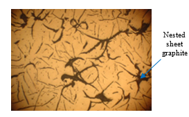
Figure 1: Microstructure of nest sheet graphite cast iron (50X magnification)
2. Experimental
2.1. Materials and Experimental Method
The material composition for the experiment is shown in Table 1. This composition is used to cast gray cast iron with grade 30 of ASTM International standard A48 for small electric motor covers whose capacity is less than 5kW. Cast iron experiments are made at Muoi Hoi Binh Duong Co., Ltd., as shown in Figure 2, without using the nodulizing elements. Initially, the mixed ingredients are fed into a medium frequency induction furnace, with a capacity of 1000kg/batch. The furnace runs for 10 minutes with low amperage to stabilize the frequency. The current then gradually increases to the maximum intensity for 1 hour 30 minutes. The crucible is covered by the acidic powder that allows desulfurization. Due to the rotating magnetic field, cast iron begins to melt and mix relatively well. The furnace is maintained at a constant current for half an hour to allow the cast iron to completely melt and the cast iron temperature is stable. Then, the cast iron temperature is increased to the pouring temperature as required. The pouring pot is pre-dried with a charcoal furnace to a temperature that is greater than 1000°C. The old sand mixture with good ventilation is used, mold is dried naturally. The mold is made by a pneumatic system to ensure uniform tightness of the mold, thus ensuring the heat transfer and exhaust mode.
Table 1: Material composition for experiment
| No. | Composition |
| 1 | Cast iron scrap, recovery materials in casting production (filling system, shrinkage, broken casting) |
| 2 | Ferrosilicon 30-70, with 1-2% |
| 3 | Ferromanganese 50-50 |
| 4 | CaCO3 |
Figure 2: Medium frequency induction furnace at Muoi Hoi Binh Duong Co., Ltd
Table 2: Overheating temperatures, holding times, and average pouring temperatures
| Sample | Average overheating temperatures (oC) |
Holding times (minutes) |
Average pouring temperatures (oC) |
| S1 | 1350 | 5 | 1350 |
| S2 | 10 | ||
| S3 | 20 | ||
| S4 | 30 | ||
| S5 | 1300 | 5 | 1300 |
| S6 | 10 | ||
| S7 | 20 | ||
| S8 | 30 | ||
| S9 | 1300 | 5 | 1260 |
Table 2 shows the cast iron samples are cast with different overheating temperatures, holding times, and average pouring temperatures. The layout of the experimental samples in the sand mold and the samples after casting are shown in Figure 3. The temperature is measured with the AS892 Infrared Thermometer. Some basic specifications are described as following: temperature range 200°C ~2200°C, accuracy ± 2°C, distance spot ratio 80:1, emissivity 0.10~1.00 adjustable, resolution 0.1°C, wavelength 900~1700 µm, response time 500ms, repeatability ±1°C.
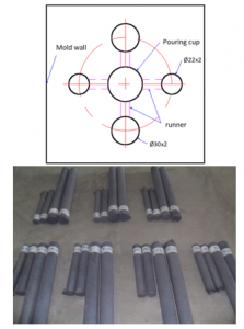
Figure 3: The layout of the experimental samples in the sand mold and the samples after casting
2.2. Methods of Observing Microstructure and Testing Mechanical Properties
Tensile test and Flexural test are conducted at Quatest 3 center, Vietnam, following the ASTM E 8/E 8M-80 (Figure 4) and ASTM A 438-80 (1997) (Figure 5) standards.

Figure 4: Tensile sample size standard ASTM E 8/E 8M-80

Figure 5: Flexural sample size standard ASTM A 438-80
The microstructure of the samples are observed at Materials Laboratory at Mechanical Faculty, University of Technology and Education, HCMC. The graphite size calculation is based on TCVN 3902-84.

Figure 6: Universal testing machine – SANS
3. Results
3.1. Effect of Holding Time on the Graphite Shape
This section considers the effect of holding times and average pouring temperatures to identify the influence of these factors on the amount of graphite and the time needed to destroy the nested sheet graphite. Figure 7 illustrates the microstructure of the samples that overheated at 1350oC and holding at 5-30 minutes. These microstructures indicate that increasing the holding time leads to a decline in the graphite amount. Moreover, the graphite shape is also different with different holding times. Improving the holding time also reduces the number of nested sheet graphite. Interestingly, if the holding time is long enough, the nested sheet graphite will disappear, as shown in Figure 7(d).

Figure 7: Microstructure of samples pouring at 1300oC at different holding time: (a) Sample S1 (holding time 5 minutes), (b) Sample S2 (holding time 10 minutes), (c) Sample S3 (holding time 20 minutes), and (d) Sample S4 (holding time 30 minutes) (50X magnification)
Figure 8 exhibits the microstructure of the samples that overheated at 1300oC and holding at 5-30 minutes. In general, improving the holding time results in a lower amount of graphite. In addition, the graphite shape is also different with different holding times. Similar to 1350oC cases, if the holding time is long enough, the nested sheet graphite will be destroyed, as shown in Figure 8(d).
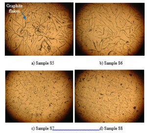
Figure 8: Microstructure of samples pouring at 1350oC at different holding time: (a) S5 (holding time 5 minutes), (b) S6 (holding time 10 minutes), (c) S7(holding time 20 minutes), and (d) S8 (holding time 30 minutes) (50X magnification)
The average size of the graphite sheet at different overheating temperatures and different holding times is showed in Figure 9. Initially, increasing the holding time from 5 to 20 minutes results in finer graphite. However, if the holding time increases to 30 minutes, the graphite size will get bigger. The smallest graphite size is achieved by holding at 20 minutes. Moreover, the graphite size at 1350oC is smaller than at 1300oC.
The reason is that with a higher temperature and a longer holding time, the liquid cast iron is stirred stronger as the viscosity of the cast iron is lower. The stronger stirring results in finer graphite. The higher temperature also causes a more stable state, and a higher trend of overcooling of the casting liquid. However, holding too long could lead to an unstable graphitization process [3,4]. When overheated, the amount and the shape of graphite changes. As the overheating of cast iron increases, the graphite becomes smaller and changes its distribution characteristics. Firstly, the eutectic form of graphite changes, then the number of dendrites will increase. Overheating facilitates the formation of graphite between dendrites which also depends on the composition of the cast iron (carbon and silicon). When the overheating temperature increases, the graphite will strongly smooth out, proving that there is some solubility of these phases and increasing the dispersion of these phases. However, overheating does not facilitate the complete dissolution or agglomeration of these phases. Traditionally, the graphite in gray cast iron could be viewed as a void, and the cracks initiate at the tip of the graphite flakes due to the micro notch stress concentration. The deformed graphite flakes, an optimized microstructure, reduced the stress concentration and prevented the expansion of cracks at the tip of graphite [11]. In [9], the author explains that cast iron slug samples all had average flake lengths of 80-100 µm, and maximum flake lengths of 1000-1400 µm due to the drastically slower cooling rate in this mold configuration compared to the cooling rate in the commercial rotors. This suggests that either there is a limit to how much the diffusivity can be improved by increased flake length or that other factors limited the diffusivity of the gray iron from these large castings. According to [16], holding time displays a reasonable effect on the progression of residual magnesium that identifies with the fading process.

Figure 9: The average size of graphite sheet with different holding times and overheating temperatures
In conclusion, the optimal microstructure is obtained by holding at 10-30 minutes at 1350oC. Casting the gray iron in the medium frequency induction furnace can destroy the nested sheet graphite.
3.2. Effect of the Holding Time on the Mechanical Properties
Table 3 and Figure 10 present the ultimate tensile strength (UTS) of the samples at different holding times and overheating temperatures. These results indicate that the UTS rises as increasing the holding time from 5 minutes to 20 minutes and gaining the best UTS value at 20 minutes. Thereafter, the UTS suffers a decline as the holding time continues to increase from 20 minutes to 30 minutes.
Table 3: Tensile test results
| Sample | Fracture force Pb (kN) |
Tensile strength σb=Pb/F0 (MPa) |
| S1 | 17.6 | 145 |
| S2 | 18.1 | 150 |
| S3 | 18.9 | 154 |
| S4 | 18.0 | 148 |
| S5 | 15.7 | 129 |
| S6 | 16.0 | 132 |
| S7 | 16.4 | 135 |
| S8 | 15.8 | 130 |

Figure 10: Ultimate tensile strength of the samples with different holding times and overheating temperatures
Table 4 and Figure 11 represent the ultimate flexural strength (UFS) of the samples at different holding times and overheating temperatures. Similar to the UTS value, the UFS increases as improving the holding time from 5 minutes to 20 minutes and reaching the highest value at 20 minutes. Then, this value decreases as the holding time increases from 20 minutes to 30 minutes. Interestingly, the results of both UTS and UFS values are consistent with the change of graphite size in section 3.1. In conclusion, the downward trend of the graphite size is fitted with an upward trend in the UTS and the UFS values. Therefore, decreasing the graphite size could lead to higher mechanical properties.
Table 4: Flexural test results
| Sample | Resistance moment W=πd3/32 (mm3) |
Ultimate flexural force Pu (kN) |
Flexural moment Mu= PuL/4 (kNmm) |
Flexural strength σbu=Mu/W (N/mm2) |
| S1 | 1148.36 | 4.31 | 328.43 | 286 |
| S2 | 1118.27 | 4.41 | 336.60 | 301 |
| S3 | 1148.36 | 4.71 | 359.44 | 313 |
| S4 | 1133.25 | 4.49 | 342.24 | 302 |
| S5 | 1133.25 | 4.03 | 307.11 | 271 |
| S6 | 1118.27 | 4.11 | 313.12 | 280 |
| S7 | 1148.36 | 4.37 | 333.02 | 290 |
| S8 | 1133.25 | 4.24 | 322.98 | 285 |

Figure 11: Flexural strength of the samples with different holding times and overheating temperatures
It can be seen that S4 and S8 samples with a holding time of 30 minutes have lower UTS and UFS values than the S3 and S7 samples with a holding time of 20 minutes. The reason is that, as the temperature and holding time increase, the viscosity will increase. The chemical composition and the amount of carbon are evenly distributed, therefore, the quality of the casting increases, the graphitization process happened more fully. However, if the temperature is too high and the holding time is too long, it will prevent the formation of liquid slag, increase the burn rate. In addition, the temperature difference between the liquid iron and the mold causes the graphitization process to occur unstably [4]. Therefore, choosing a holding time of 10-30 minutes is optimal.
The samples overheated at 1350°C and 1300°C gave different mechanical results. The reason is overheating changes the nature of the liquid phase and the differentiation conditions when solidified. On the one hand, overheating increases the stability of the liquid phase and increases its tendency to overcool. On the other hand, under the ideal solidification of a casting in a mold, overheating causes the preheating of the mold and changes the cold condition of the cast iron. Overheating requires a regular increase in the amount of bound carbon (reducing the amount of graphite) due to increased liquid phase stability and its tendency to over-cool. Overheating will limit impurities present in the liquid phase and make them more evenly distributed. In addition, the different overheating temperature will result in different morphology of graphite. The study [11] showed that the distribution and morphology of graphite has a direct influence on the properties of gray cast iron oriented the space orientation of the graphite flakes in gray cast iron and improved both strength and ductility.
3.3. Effect of the Average Pouring Temperature on the Graphite Size and the Mechanical Properties
This section surveys the effect of the average pouring temperature on the graphite size and the mechanical properties of the gray iron. The samples S1, S5, and S9 are chosen and analyzed.
Figure 12 and Table 5 show the microstructure of the cast iron and the average size of their graphite. These results indicate that decreasing the average pouring temperature will cause a rise in the graphite average size.

Figure 12: Microstructure of samples pouring at different temperatures: (a) Sample S1, (b) Sample S5, and (c) Sample S9 (50X magnification)
Table 5: The effect of the average pouring temperature to the graphite size
| Sample | Holding time (minutes) |
Average pouring temperature (oC) |
Average size of graphite (mm) |
| S1 | 5 | 1350 | 0.307 |
| S5 | 5 | 1300 | 0.312 |
| S9 | 5 | 1260 | 0.339 |
Table 6: UTS and UFS values at different average pouring temperatures
| Sample | Average pouring temperature (oC) |
UTS value (MPa) |
UFS value (N/mm2) |
| S1 | 1350 | 145 | 286 |
| S5 | 1300 | 129 | 271 |
| S9 | 1260 | 126 | 270 |
The UTS and UFS of the sample S1, sample S5, and sample S9 values at different average pouring temperatures is demonstrated in Table 6. The result points out that reducing the pouring temperature leads to a decline in the UTS and UFS values. The result is that the lower pouring temperature leads to the larger graphite size. Therefore, the larger graphite size will result in lower mechanical characteristics. Moreover, the higher temperature of the casting liquid will cause a lower viscosity and a better chemical uniformity. At a low pouring temperature of 1260oC (sample S9), the viscosity of the casting liquid is high, the chemical composition is not evenly distributed. To achieve a higher level of uniformity, the casting liquid can behold for a longer time. However, the longer time will cause a loss in the chemical composition as they are burned out or going to the slag. Generally, to improve the mechanical properties of the gray iron, increasing the temperature is better than increasing the holding time. Increasing to too high a temperature will result in a worse slag, a higher level of chemical burning, and the more unstable the graphitization [14].
In conclusion, the optimal pouring temperature to obtain the best mechanical properties is 1300-1350oC.
4. Conclusion
Increasing the holding time from 5 to 20 minutes at 1350oC and 1300oC results in finer graphite, a smaller amount of nested sheet graphite. The finest graphite size is achieved at 20 minutes. Holding up to 30 minutes could destroy the nested sheet graphite, in which at 1300°C the holding time will be longer than overheating and keep the heat at 1350°C to completely lose the nested sheet graphite. However, increasing the holding time to 30 minutes will cause an increase in the graphite size.
– At 1350oC and 1300oC, the UTS and UFS values increase as the holding time improve from 5 to 20 minutes, and reaching the highest values at 20 minutes. Thereafter, these mechanical properties suffer a decline as the holding time increase from 5 to 20 minutes. The finer graphite results in higher UTS and UFS values.
– Declining the average pouring temperature from 1350oC to 1300oC, and then 1260oC (with holding time in 5 minutes and same cooling condition) leads to a finer graphite size and the better UTS and UFS values.
From the above results, the casting conditions that can improve the product quality is the optimal average pouring temperature is 1300-1350°C, while the optimal holding time is 10-30 minutes which will completely lose the nest graphite.
Conflict of Interest
The authors declare no conflict of interest.
Acknowledgment
We acknowledge HCMC University of Technology and Education, Dong Nhan Phat Co., Ltd and Material Testing Laboratory (HCMUTE). They gave me an opportunity to join their team, accessed the laboratory and research machines. Without their appreciated support, it would not be possible to conduct this research.
- T. H. N. Pham, N. T. Tran, P. J. Pritadewi, N. Y. P. Vo. “Research on Factors Influencing the Formation Graphite and Effect of Graphite on Mechanical Properties of Gray Cast Iron”. 2019 International Conference on System Science and Engineering (ICSSE), Dong Hoi, Vietnam, 2019, doi:10.1109/ICSSE.2019.8823478.
- Y. Liu, J. Xing, Y. Li, S. Wang, D. Tao. “Tomographical Study of the Effect of Graphite on Properties of Cast Iron”, Steel research international, 2018, doi:10.1002/srin.201800086.
- X. Huang, Y. Ye, X. Shen, X. Chang. “The mechanical properties of gray cast iron and metallographic structure effect on the chip shape”, Advanced Materials Research, 339, 200-203, 2011, doi:10.4028/www.scientific.net/AMR.339.200.
- I. Svensson, T. Sjögren. “On Modeling and Simulation of Mechanical Properties of Cast Irons with Different Morphologies of Graphite”, International Journal of Metalcasting, 3(4), 67-73, 2009, doi:10.1007/BF03355460.
- S. Kumar, P. Kumar, H. S. Shan. “Optimation of Tensile Properties of Evaporative Casting Process through Taguchi’s Method”. Journal of Materials Processing Technology, 204, 59-69, 2008, doi:10.1016/j.jmatprotec.2007.10.075.
- E. Lunarska. “Effect of graphite shape on the corrosion of gray cast iron in phosphoric acid”, Materials and Corrosion, 47, 539-544, 1996, doi:10.1002/maco.19960471002.
- H. Nakae, H. Shin. “Effect of Graphite Morphology on Tensile Properties of Flake Graphite Cast Iron”. Materials Transactions, 42(7), 1428-1434, 2001, doi:10.2320/matertrans.42.1428.
- M. Tsujikawa, K. Nagamine, A. Ikenaga, M. Hino. “Influence of graphite morphology on dry sliding wear of flake graphite cast irons”. International Journal of Cast Metals Research, 21(1-4), 76-80, 2008, doi:10.1179/136404608X361701.
- R. L. Hecht, R. B. Dinwiddie, H. Wang. “The effect of graphite flake morphology on the thermal diffusivity of gray cast irons used for automotive brake discs”. Journal of Materials Science, 34(19), 4775-4781, 1999, doi:10.1023/a:1004643322951.
- M. C. Rukadikar, G. P. Reddy. “Influence of chemical composition and microstructure on thermal conductivity of alloyed pearlitic flake graphite cast irons”. Journal of Materials Science, 21, 4403-4410, 1986, doi:10.1007/bf01106563.
- W. Wang, T. Jing, Y. Gao, G. Qiao, X. Zhao. “Properties of a gray cast iron with oriented graphite flakes”. Journal of Materials Processing Technology, 182(1-3), 593-597, 2007, doi:10.1016/j.jmatprotec.2006.09.028.
- R. Hinrichs, M. A. Z. Vasconcellos, W. Österle, C. Prietzel. “Amorphization of Graphite Flakes in Gray Cast Iron Under Tribological Load”. Materials Research, 21(4), 2018, doi:10.1590/1980-5373-MR-2017-1000.
- M.M. J. Behnam, P. Davami, N. Varahram. “Effect of cooling rate on microstructure and mechanical properties of gray cast iron”, Materials Science and Engineering, A528, 583-588, 2010, doi:10.1016/j.msea.2010.09.087.
- Suyitno, Sutiyoko. “Effect of Pouring Temperature and Casting Thickness on Fluidity, Porosity and Surface Roughness in Lost Foam Casting of Gray Cast Iron”, Procedia Engineering, 50, 88-94, 2012, doi:10.1016/j.proeng.2012.10.011.
- T. Sjogren, P. Vomacka, I. L. Svensson. “Comparison of mechanical properties in flake graphite and compacted graphite cast irons for piston rings”. International Journal of Cast Metals Research, 17(2), 65-71, 2004, doi:10.1179/136404604225017474.
- H. Megaheda, E. El – Kashifa, A. Y. Shashab, M. A. Essam. “Effect of holding time, thickness and heat treatment on microstructure and mechanical properties of compacted graphite cast iron”, Journal of Materials Research and Technology, 8(1), 1188-1196, 2019, doi:10.1016/j.jmrt.2018.07.021.