Wideband and High-Gain Aperture Coupled Feed Patch Array Antenna for Millimeter-Wave Application
Volume 5, Issue 5, Page No 559-562, 2020
Author’s Name: Dat Vuong1, Nam Ha-Van2, Tran The Son1,a)
View Affiliations
1Vietnam-Korea university of information and communication technology, Information Technology, Danang, 550000, Vietnam
2Soongsil University, Department of Information Communication, Materials, and Chemistry Convergence Technology, Seoul, 100011, Korea
a)Author to whom correspondence should be addressed. E-mail: ttson@vku.udn.vn
Adv. Sci. Technol. Eng. Syst. J. 5(5), 559-562 (2020); ![]() DOI: 10.25046/aj050569
DOI: 10.25046/aj050569
Keywords: Aperture coupled feeding patch (ACFP), Array antenna, Millimeter-wave, Wide bandwidth

Export Citations
Millimeter-wave (mmW) antenna is one of the most important parts of the fifth-generation (5G) systems because of its advanced characteristics, for example, wideband and high transmission rate. In this paper, an mmW 4×1 array antenna with high gain and wideband based on an aperture coupled feeding patch (ACFP) antenna is presented. The proposed array antenna operates at 28-GHz frequency. The antenna has a wide operating bandwidth of around 12.6 % at -10 dB bandwidth that covers 26.65 GHz to 30.35 GHz. The peak gain of the array antenna is approximately 13 dBi at 28 GHz and kept maintained in all interested frequency band. The proposed antenna is designed using a 0.127-mm thick Duroid 5880 substrate with a compact substrate of dimensions of 25 mm x 48 mm x 0.754 mm.
Received: 14 July 2020, Accepted: 16 September 2020, Published Online: 05 October 2020
1. Introduction
Fifth-generation (5G) communication system has recently drawn increased attention for supporting tens to hundreds of times more capacity compared to the current 4G cellular network [1]–[4]. A bigger system capacity with wide bandwidth and high frequency is required to mitigate the higher path loss at mmW frequencies for a 5G system [5]. Furthermore, the shorter wavelengths of mmWs from installation perspectives are conducive to the reduction of antenna size that allows the incorporation of multiple patches or arrays in compact devices. Therefore, wide bandwidth and high transmission gain are two popular problems of mmW antenna design.
Several types of antenna have been recently proposed for mmW 5G system, such as dielectric-loaded planar inverted-F antenna [6, 7], microstrip leaky-wave antenna (LWA) [8]–[10], arrays of half-width microstrip LWA [11, 12], etc. In most cases, the bandwidth is narrow. In this paper, an aperture coupled feeding patch (ACFP) antenna is proposed to improve the bandwidth of the microstrip antenna. The ACFP antenna is an indirectly feeding method for the resonant patch that includes two substrates separated by a ground plane [13, 14]. To increase the transmission gain, a 4×1 array ACFP antenna is designed to obtain around 13 dBi gain at 28 GHz frequency with a compact size of 25 mm x 48 mm x 0.754 mm.
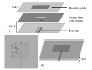
Figure 1: Single ACFP antenna structure: (a) separated components view; (b) top view and perspective view.
The organization of this paper is presented as follows. The proposed antenna’s structure is described in Section II. The fabrication and experimental results are presented in Section III.
2. Array Antenna Structure Design
Figure 1(a) shows the single ACFP antenna structure that has two substrates separated from each other. The top substrate has the radiating patch antenna element with a dimension of Lp = 3.6 mm and Wp = 4.2 mm, and the bottom substrate has a transmission feed line with a thickness of 0.4 mm and a length Lf = 4.5 mm. A small aperture is slotted in the ground plane to create coupling from the open-circuited feed line to the radiating patch. A rectangular aperture is generally placed in the patch central to maximize the coupling and generate the symmetric radiation pattern, which has a length Lap = 2.2 mm and width Wap = 0.4 mm. In this design, two substrates are separated by a ground plane and a small gap of 0.5 mm that can enhance the bandwidth and reduce the interference from the feed network to the main radiation pattern. A tapered line feed network is designed to array four ACFP antenna elements with small mutual coupling and internal reflections. With a conventional array antenna, radiating elements are normally separated by smaller half-wavelength. If the element spacing between two adjacent antennas is larger than a half-wavelength, the antenna gain decreases, and the grating lobe increases [15]. However, the element patch width is usually used in the order of 0.4-0.5 λ0, which is conducive to a small remaining distance between the adjacent elements. This small distance would cause high mutual coupling. With the ACFP array antenna, the distance between the adjacent patch elements is chosen to be higher than a half wavelength [16]–[18].
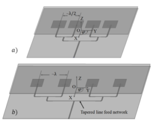
Figure 2: 4×1 ACFP array antenna with a tapered line feed network: a) 4×1 half wavelength spacing (HWS) array antenna; b) proposed 4×1 array antenna.
In this paper, a 4×1 half-wavelength spacing (HWS) array antenna is considered to verify the performance. Besides, a proposed 4×1 array antenna is optimized and compared to the performance with the 4×1 HWS array antenna. The 4×1 HWS array antenna and the proposed 4×1 array antenna are illustrated in Figure 2. Both antennas are designed using Duroid 5880 with the permittivity ε of 2.2 and the thickness of 0.127 mm for both layer substrates. The ANSYS HFSS software (ANSYS Inc. Canonsburg, PA, USA) was used to design, simulate, and optimized the antenna. The return loss S11 parameters, radiation patterns, and antenna gains in the simulation for the single antenna, the 4×1 HWS array antenna, and the proposed 4×1 array antenna are shown in Figure 3. The -10 dB bandwidth of the antennas cover the 28-GHz frequency band with almost higher than 12 % bandwidth that is shown in Figure 3(a). The bandwidth of the array antenna is a bit larger and shifted up than the single antenna.
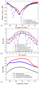
Figure 3: Simulation results of the single ACFP antenna, the 4×1 HWS array antenna, and the 4×1 array antenna: a) S11 parameters; b) radiation patterns; c) antenna gains.
A comparison of the radiation pattern and the realized gain between the single antenna, the 4×1 HWS array antenna, and 4×1 array antenna was demonstrated in Figure 3(b) and Figure 3(c) with the single antenna gain of around 9.45 dBi, the HWS array antenna of 13 dBi and the array antenna gain of 15.37 dBi. Because the tapered line feed network presented a good power divider with a small reflection, then the array can obtain a significant gain enhancement compared to the single. However, the radiation pattern of the array antennas is sharper and thinner at the plane of Phi = 0o than the one of the single antenna. Normally, an HWS array antenna presents a better side lobe level (SLL) compared to a larger spacing array antenna. However, the SLL of the 4×1 HWS array antenna shows a worse value than the one of the optimal 4×1 array antenna with the element spacing around wavelength. In detail, the SLL of the HWS array antenna is -14.34 dB, while the SLL of the proposed optimal array antenna is -16.54 dB. Furthermore, the antenna gains on the overall interested frequency band of the optimal array antenna are significantly higher than the one of the HWS array antenna with almost 2dB on overall frequency band as shown in Figure 3(c).
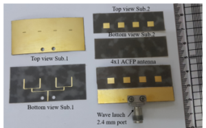
Figure 4: Fabrication of the 4×1 array antenna with the top view and bottom view of each layer substrate.
3. Array Fabrication and Measurement Results
Based on the analysis and design of the above section, the proposed array antenna was fabricated and measured to validate the performance, as demonstrated in Figure 4. The proposed antenna is printed on a 0.127-mm thick Duroid 5880 substrate. The bottom substrate contains a tapered line feed network on the bottom side and a ground plane with four aperture slots on the top side of the substrate, and the size is 25 mm x 48 mm. The top substrate has four radiating patches on the top side of the substrate. There is a small gap of 0.5 mm between two substrates that is an important factor to enhance the bandwidth of the antenna. A thin Styrofoam material was inserted between two layers to straight the antenna and fix the small gap between them. The antenna was connected to a Wave launch 2.4 mm port that can work at 28 GHz frequency band with low loss, wideband, and the terminal impedance of 50 Ω. This port has two screws to firm the antenna with the port. Therefore, two small holes are drilled nearby the feeding network, as shown in the view of Sub. 1. The radiation pattern and antenna gain were measured in a far-field chamber with the configuration setup as shown in Figure 5. The return loss was measured using an 8510C Vector Network Analyzer. The measured S11 parameter of the 4×1 array antenna is shown in Figure 6(a). The -10 dB bandwidth for the antenna frequency covers 26.65 GHz to 30.35 GHz, which is slightly different from the one in the simulation result. However, the proposed antenna still covers the interested frequency band. The radiation pattern of the proposed antenna at 28 GHz frequency is shown in Figure 6(b). There is a good agreement between the simulation and measurement results of the radiation pattern. The antenna gain at 28 GHz frequency in the measured result is slightly lower than the simulated gain because of the fabricated tolerance and losses in the measurement process. From the measured radiation pattern, the antenna presents a good performance with the side lobe level (SLL) of approximately -13.2 dB. The antenna gain is also measured in the overall wideband from 26 GHz to 30 GHz, which is depicted in Table 1. It can see that the antenna gain is kept unchanged around 13 dBi on all frequency bands. A comparison between the proposed array antenna and the related works in some important factors, such as overall size, the -10 dB bandwidth, and antenna gain are presented in Table 2. Both array antennas in [16, 17] were based on the ACFP structure which was arrayed 4×1 in series. From this Table, it is obvious that the proposed array antenna is significantly compact size, wider bandwidth, and higher gain compared with the referred antennas.
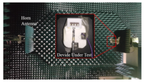
Figure 5: Configuration setup of the proposed array antenna for the measurement process.
Table 1: The measured antenna gain in the interested frequency band.
| Freq. (GHz) | 26.5 | 27 | 27.5 | 28 |
| Gain (dBi) | 12.2 | 12.86 | 13.03 | 13.06 |
| Freq. (GHz) | 28.5 | 29 | 29.5 | 30 |
| Gain (dBi) | 13.32 | 13.3 | 13.69 | 13.34 |
4. Conclusions
In this paper, a 4×1 array antenna using an ACFP antenna structure has been presented. The proposed antenna has a compact size of 25 mm x 48 mm x 0.754 mm and is printed on a Duroid 5880 substrate with a thickness of 0.127 mm for both layer substrates. A wideband and high gain of the antenna is obtained with around 12.6 % bandwidth and approximately 13 dBi, respectively.
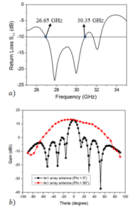
Figure 6: Measured results of the 4×1 array antenna: a) S11 parameter; b) radiation pattern and gain at 28 GHz frequency.
Table 2: Comparison of the proposed antenna with those of related works.
| Ref. | Substrate | Overall
Size (λ0) |
BW
(%) |
Gain (dBi) |
| [16] | 0.127 mm thick
Rogers 6002 28 GHz |
2.8 x 0.93 x
0.088 |
∼ 7.1 | 13.5 |
| [17] | 0.127 mm thick
Rogers 5880 60 GHz |
5 x 3 x
0.076 |
∼ 6.7 | 12.5 |
| This work | 0.127 mm thick
Rogers 5880 28 GHz |
2.33 x 4.48 x
0.07 |
∼ 12 | 13.69 |
- J. G. Andrews, S. Buzzi, W. Choi, S. V. Hanly, A. Lozano, A. C. K. Soong, C. Zhang, “What Will 5G Be?” IEEE Journal on Selected Areas in Communications, 32(6), 1065–1082, 2014.
- T. S. Rappaport, S. Sun, R. Mayzus, H. Zhao, Y. Azar, K. Wang, G. N. Wong, K. Schulz, M. Samimi, F. Gutierrez, “Millimeter Wave Mobile Communications for 5G Cellular: It Will Work!” IEEE Access, 1, 335–349, 2013.
- N. Ha-Van, C. Seo, “A Single-Feeding Port HF-UHF Dual-Band RFID Tag Antenna,” J Electromagn Eng Sci, 17(4), 233–237, 2017, doi:10.26866/jees. 2017.17.4.233.
- Z. Pi, F. Khan, “An introduction to millimeter-wave mobile broadband systems,” IEEE Communications Magazine, 49(6), 101–107, 2011.
- S. Rangan, T. S. Rappaport, E. Erkip, “Millimeter-Wave Cellular Wireless Net- works: Potentials and Challenges,” Proceedings of the IEEE, 102(3), 366–385, 2014.
- K. M. Morshed, K. P. Esselle, M. Heimlich, D. Habibi, I. Ahmad, “Wideband slotted planar inverted-F antenna for millimeter-wave 5G mobile devices,” in 2016 IEEE Region 10 Symposium (TENSYMP), 194–197, 2016.
- K. M. Morshed, K. P. Esselle, M. Heimlich, “Dielectric loaded planar inverted- F antenna for millimeter-wave 5G hand held devices,” in 2016 10th European Conference on Antennas and Propagation (EuCAP), 1–3, 2016.
- D. K. Karmokar, K. P. Esselle, T. S. Bird, “Wideband Microstrip Leaky-Wave Antennas With Two Symmetrical Side Beams for Simultaneous Dual-Beam Scanning,” IEEE Transactions on Antennas and Propagation, 64(4), 1262–1269, 2016.
- D. K. Karmokar, Y. J. Guo, P. Qin, K. P. Esselle, T. S. Bird, “Forward and Backward Beam-Scanning Tri-Band Leaky-Wave Antenna,” IEEE Antennas and Wireless Propagation Letters, 16, 1891–1894, 2017.
- M. Garcia-Vigueras, J. L. Gomez-Tornero, G. Goussetis, A. R. Weily, Y. J. Guo, “Enhancing Frequency-Scanning Response of Leaky-Wave Antennas Using High-Impedance Surfaces,” IEEE Antennas and Wireless Propagation Letters, 10, 7–10, 2011.
- D. K. Karmokar, K. P. Esselle, T. S. Bird, “An Array of Half-Width Microstrip Leaky-Wave Antennas Radiating on Boresight,” IEEE Antennas and Wireless Propagation Letters, 14, 112–114, 2015.
- D. K. Karmokar, K. P. Esselle, S. G. Hay, “Four-branch microstrip leaky-wave antenna array for radiation towards broadside,” in 2014 International Workshop on Antenna Technology: Small Antennas, Novel EM Structures and Materials, and Applications (iWAT), 96–99, 2014.
- G. Kumar, K. P. Ray, Broadband microstrip antennas, Artech House Inc., 2003.
- N. N. Yoon, N. Ha-Van, C. Seo, “High-gain and wideband aperture coupled feed patch antenna using four split ring resonators,” Microwave and Optical Technology Letters, 60(8), 1997–2001, 2018, doi:10.1002/mop.31284.
- T. Suda, T. Takano, Y. Kazama, “Grating lobe suppression in an array antenna with element spacing greater than a half wavelength,” in 2010 IEEE Antennas and Propagation Society International Symposium, 1–4, 2010.
- K. Phalak, A. Sebak, “Aperture coupled microstrip patch antenna array for high gain at millimeter waves,” in 2014 IEEE International Conference on Communication, Networks and Satellite (COMNETSAT), 13–16, 2014.
- I. Mohamed, A. R. Sebak, “High-gain series-fed aperture-coupled microstrip antenna array,” Microwave and Optical Technology Letters, 57(1), 91–94, 2015, doi:10.1002/mop.28792.
- M. . Li, S. Kanamaluru, K. Chang, “Aperture coupled beam steering microstrip antenna array fed by dielectric image line,” Electronics Letters, 30(14), 1105–1106, 1994.
Citations by Dimensions
Citations by PlumX
Google Scholar
Scopus
Crossref Citations
No. of Downloads Per Month
No. of Downloads Per Country