Multi Closed-loop Adaptive Neuro-Fuzzy Inference System for Quadrotor Position Control

Adv. Sci. Technol. Eng. Syst. J. 5(5), 526–535 (2020);
 DOI: 10.25046/aj050565
This paper deals with a multi closed-loop adaptive neuro-fuzzy inference system (ANFIS) design for the under-actuated quadrotor systems. First, the training data set for the fuzzy inference system is obtained using a proportional integral derivative controller. Then, an initial ANFIS controller is designed, where the integral control action is preserved in the multi-closed-cloop ANFIS for each quadrotor system state. Thereafter, scaling gains are added to the controller inputs/outputs, and a multidimensional PSO algorithm is used to tune all the control parameters. Besides, using a simulation example, the aerial vehicle performances are investigated in the presence of an unknown payload mass parameter. Specifically, the position tracking performances of the proposed multi closed-loop PSO-based ANFIS plus integral control strategy is compared with the classical PID, conventional ANFIS, and non-optimized ANFIS plus integral controllers. Thus, using the conducted simulation results, it results that the multi closed-loop PSO-based ANFIS plus integral can achieve perfect translational trajectory-tracking and ensure better attitude stabilization despite unknown quadrotor payload mass parameter. Therefore, the proposed new multi closed-loop PSO-based control strategy may be considered as an efficient controller when considering an arbitrary trajectory-tracking problem for the quadrotor system.
1. Introduction
In recent years, a growing number of researchers have been interested in quadrotor aerial vehicles as a result of their vertical take-off and landing (VTOL) ability, accurate hovering, good behavior even in case of severe maneuverability, and low cost. Then, the growing utilization of these unmanned aerial vehicles (UAV) has begun for all types of tasks. For instance, these aerial vehicles are commonly utilized in smart farming [1], real-time mapping while exploring confined spaces such as tunnels and mines [2], and air travel [3]. However, although the quadrotor has become a successful UAV, this aerial robot is an underactuated and coupled system. Thus, to control this nonlinear system, several approaches have been presented. However, designing an efficient control strategy for this aerial vehicle is still a difficult task. In the literature, different methods have been used to ensure the quadrotor flight stabilization. First, prominent control approaches for quadrotor attitude stabilization and trajectory-tracking control include the proportional-integral-differential (PID) controller [4]. However, despite this control approach could ensure flight stabilization for hovering state, it cannot stabilize the quadrotor in presence of external disturbances. Also, using a simplified dynamic model, the position control could be achieved using a nested loop based backstepping control strategy [5]. Furthermore, the backstepping technique was combined with integral control, which allows bringing together the backstepping robustness against disturbances, with the integral control robustness against model uncertainties (see e.g. [6], [7], and [8]). The result was an integral backstepping control (IBC) scheme that could be used for attitude stabilization as well as for trajectory tracking control. However, although the altitude control objective was ensured, the vehicle hovering still shows attitude oscillations (see e.g. [9]).
Besides, as a powerful tool for controlling nonlinear systems, many (integral) sliding mode controllers were designed for stabilizing the quadrotor attitude (see e.g. [10]). However, a persistent shattering effect was observed on the vehicle attitude, although the stable hovering was achieved. Therefore, due to its switching control behavior, which is not acceptable by quadrotor
dynamics, perfect autonomous quadrotor flight cannot be ensured using a sliding mode control strategy. Then, to compensate for parameter uncertainty, many adaptive control strategies are also proposed for controlling the quadrotor position (see e.g. [11]), with satisfactory results despite the yaw angle was poorly stabilized.
Interestingly, several fuzzy logic controllers (FLC) are also proposed for the autonomous quadrotor flight control (see e.g. [12], [13]). Indeed, to achieve the attitude stabilization as well as position tracking control, fuzzy logic control is usually utilized. To test the proposed fuzzy control performances, a few results have shown that efficient position control may are obtained for smooth trajectory tracking, despite poor vehicle attitude stabilization. Roughly, using only fuzzy logic controllers, the quadrotor attitude and its vertical position control problem could be solved using a reduced intelligent fuzzy-based controller (see e.g. [14]). Specifically, combining the two above controllers with a metaheuristic optimization tool permits obtaining better performances. For instance, a PID-like structure consists of using a fuzzy controller that utilizes the error, its derivative, and its integral as input signals. Interestingly, each input is applied through a block whose gain is adjustable. Moreover, the control action (i.e. the controller output) may also be applied through a block whose gain could be tuned. Thus, using an optimization algorithm, all the scaling-gains could be independently adjusted, which allows improving the controller performances. Namely, the provided simulation results show good attitude stabilization and stable reference trajectory tracking for the (x,y,z)-position and -yaw rotation (see e.g. [15] [16]). However, the robustness of the proposed controllers was not sufficiently highlighted. Besides, artificial neural networks (ANN) have shown their effectiveness in controlling unmanned aerial vehicles [17]. Specifically, the fuzzy logic controller utilizes expert knowledge in establishing the rule-base [18], while artificial neural networks learn system operations utilizing neurons in almost a similar way the human beings do [19]. Interestingly, a new control strategy denoted adaptive neuro-fuzzy inference system (ANFIS) has appeared, which allows benefiting from FLC as well as ANN control approaches. For instance, using quadrotor tests, the ANFIS was shown to be as good as a type-2 fuzzy controller [20]. Then, compared to conventional proportional-integral-differential control, a multi-disturbance simulation scenario has shown that the ANFIS controller can enhance the quadrotor trajectory-tracking performances [21]. Indeed, to implement its inner fuzzy inference subsystem, the ANFIS approach can construct its knowledge utilizing training data from any classical controller. Interestingly, while designing the ANFIS controller, adding (input-output) scaling-gains can improve the control system robustness, which necessitates using an optimization or teaching-learning algorithm [22]. Especially, the particle swarm optimization still proves its high efficiency in ANFIS design, whether for tuning the membership functions [23] or for tuning the rule base of the inference mechanism [24].
Considering the above presentation, this work presents the ANFIS design steps for controlling a quadrotor UAV whose payload mass parameter is assumed to be unknown during the aerial vehicle flight. Thus, we first present the learning ANFIS controller design step, where the necessary training data set is collected from a classical proportional-integral-differential controller. Then, the other ANFIS design steps are described in detail. Specifically, this work presents an improved structure of the ANFIS control strategy, namely the multi closed-loop ANFIS plus integral control action, where an additional integral control action is shown to be improving the quadrotor control system performances. Roughly, as the steady-state operation of a quadrotor is hovering, it results that an integral control can compensate for unmodeled dynamics and parameter deviations. For this reason, the initial integral control action is maintained as an additional component in the proposed ANFIS, which makes the proposed control strategy a new multi closed-loop control structure [25]. Then, to improve the ANFIS performances, the state error signals are applied to the controller inputs through linear blocks whose scaling factors could be optimized. Besides, after the optimization process, the resulting control system performances are compared to those obtained using a classical PID and the conventional (non-optimized) ANFIS controllers. It turns out that the multi closed-loop PSO-based ANFIS plus integral controller can show better tracking control performances and better compensation for external disturbances.
It is worth noticing that the ingredients of the proposed idea have been presented in previous authors’ work [26]. However, the main idea of the present paper is fully rewritten to make the proposed control strategy concisely designed with a complete quadrotor system model, without using the small-angle assumption. Besides, to show the robustness and the effectiveness of the proposed multi closed-loop ANFIS plus integral control strategy, both internal, as well as external disturbances, are here taken into account and shown to be compensated for.
This work comprises five sections. First, the quadrotor mathematical model is described in section 2. Then, in section 3, the PSO-based adaptive neuro-fuzzy inference system plus integral design steps are described. To show the effectiveness of the enhanced ANFIS control strategy, a simulation example is provided and commented in section 4. Finally, a concluding summary ends the paper.
2. Quadrotor Mathematical Model
The main actuation of a quadrotor is based on the rotors that are equidistant from the vehicle center of gravity (COG). Thus, this aerial vehicle motion is usually controlled utilizing the relative speed of its four actuators. However, the three rotations around the Euler angles, and the linear motions along the three axes, make the quadrotor a six-degree-of-freedom (6DOF) system. For this reason, the quadrotor is said under-actuated because it has only four control inputs.
2.1. Quadrotor kinematic model
The quadrotor is a symmetrical structure, which can rotate around its three axes. Then, studying its dynamics involves two frames. First, the body-fixed frame , where is the vehicle center of gravity. Then, the inertial frame , where O is an arbitrarily chosen origin in the space (see Figure 1).
Thus, w.r.t -frame, let denote the absolute vehicle CoG position, and denote the vehicle attitude and orientation, where ( , , ) denote respectively the roll, pitch, and yaw Euler angles. However, to
avoid the gimbal lock problem, let us consider the following usual assumption:
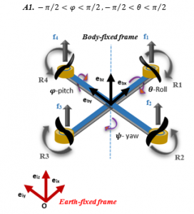
Figure 1: Quadrotor X-structure and frames
Now, let us notice that the well-known rotation matrix from -frame to -frame is given by [27]:
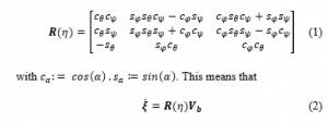
where and denote respectively the earth-fixed and body-fixed vehicle linear velocities.
Now, concerning angular velocities, the transformation matrix from the -frame to the -frame is denoted the transfer matrix and is given by [27]
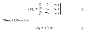
where denotes the Euler angles rates, and denotes the body-fixed angular velocity.
2.2. Quadrotor dynamic model
Assuming that the quadrotor rotors do rotate at , it results that each quadrotor actuator generates a thrust force that is given by . Thus, the total upward thrust writes:
![]()
where . Then, considering the -earth-fixed frame, and using solid mechanics, the total upward thrust writes:
![]()
Thus, using Newton formalism for translational motions, the quadrotor translational dynamics are described by:
![]()
where m denotes the aerial vehicle total mass, and denotes the quadrotor weight vector, which is given by:
![]()
where stands for the gravity acceleration.
Now, to describe the aerial vehicle rotation motion, let us recall that the above thrust forces do also produce the following torques:
where denotes the distance between each rotor and the quadrotor center of mass. denotes the drag constant.
Thus, using Newton formalism for rotational motions, the aerial vehicle rotation dynamics are described by:
![]()
where denotes the inertia matrix, and denotes the above body-fixed angular velocity defined in (4).
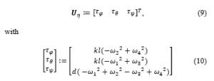
Then, let us notice that, using the following vectors:
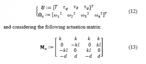
it results that the control distribution from the actuating motors may be described by:
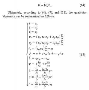
Now, considering the above quadrotor dynamics, and using enhanced fuzzy control strategies, our objective is guaranteeing the tracking-control of arbitrary position for any -yaw orientation, and ensuring the stabilization of ( ) attitude angles, in presence of unknown aerial vehicle payload mass parameter.
3. Multi Closed-loop PSO-based ANFIS plus Integral Controller
3.1. Problem statement
From the above objective, let us design the system inputs, namely the vector , which allows ensuring the tracking of -reference trajectory for arbitrary -yaw orientation, and the stabilization of quadrotor attitude, despite random payload mass change during the vehicle flight, which also means a change of the matrix inertia. More concisely, we aim to stabilize the quadrotor system while tracking a position reference trajectory with the constraint to keep small overshoot and small rise and settling times, despite the presence of external disturbances. Then, it is worth noticing that because of quadrotor under-actuation, the control system structure may be designed using two control subsystems. Namely, an upstream control subsystem whose role is to ensure the reference trajectory tracking, and a downstream control subsystem whose role is stabilizing the vehicle attitude.
3.2. PSO-based ANFIS plus integral algorithm
Now, we briefly describe the proposed PSO-based adaptive neuro-fuzzy inference system plus integral (ANFIS+I) control strategy that is based on a Multi-Closed-loop ANFIS controller, where the additional control scaling gains are optimized using a multidimensional PSO algorithm. For clarity, algorithm 1 enumerates the main steps of the code to implement using a simulation tool (e.g. Matlab). For clarity, the methodology of the PSO-based ANFIS+I control design may be summarised using algorithm 1.
| Algorithm 1: PSO-based ANFIS+I control algorithm |
| Collect training data
Generate ANFIS controller ANFIS Enhancement with integral control ANFIS+I scaling factors optimization using PSO |
3.3. ANFIS architecture
The adaptive neuro-fuzzy inference system (ANFIS) algorithm was firstly introduced by Jang in 1993 [28], which was considered as an intelligent hybrid algorithm based on the benefits of both fuzzy logic control (FLC) and artificial neural network (ANN) approaches. The idea started from the fact that to design a suitable FLC for the considered plant, we need a minimum of knowledge upon the system functioning, which allows us to define the fuzzy rules of the controller. Then, we should define the membership function type and degree. For this reason, the design of this control is considered a complicated task despite the wide use of the FLC system in control engineering [29]. Thus, to compensate for the disadvantages of the FLC system, the artificial neural network (ANN) is also used. Roughly, the ANN algorithm may be utilized during the learning process, which can approximate an unknown function from the system inputs and outputs data set, using a multitude of neurons in a similar way of a human-being brain.
Indeed, through five layers of the ANN algorithm, the system output is computed from inputs using several inference system parameters such as the fuzzy rules number and the membership function type and degree. For clarity, Figure 2 shows the ANFIS architecture model.
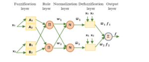
Figure 2: ANFIS architecture with two membership function
Now, the learning process of the ANFIS algorithm may be described as follows:
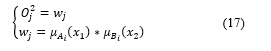
First, in the fuzzification layer, the output of each node is computed from the following equation:
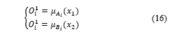
where are the inputs, ) are the node linguistic label, where varies from 1 to the membership function number.
Then, to compute the output node of the second layer, we use the product of each input entering into the node as follows:
where varies from 1 to the fuzzy rule number and is a rule-coefficient that stands for the firing strength.
Now, to compute the value of each node in the normalization layer, each firing strength is divided by the sum of all firing strength, which is denoted by the normalized firing strength according to the following equation:
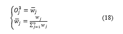
where varies from 1 to
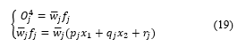
Then, in the defuzzification layer, using the normalized firing strength and the consequent parameters , we compute a weighted value of each fuzzy rule using the following equation:
Thus, the final unique node value obtained in the output layer is computed by adding the incoming inputs according to the following equation:
3.4. ANFIS algorithm design
To design the ANFIS controller, the first step is the collection of learning data. Indeed, this learning process is very important while designing the ANFIS controller. In this work, we choose to select the training data set from a proportional-integral-differential controller. Then, benefiting from the symmetrical structure, to control the six-state quadrotor system, namely , only four P(I)D controllers are necessary. Roughly, similar PD controllers are used for the horizontal positions and , similar controllers are used for the attitude Euler angles and , a PID control structure is used for the quadrotor altitude and for controlling the -yaw quadrotor orientation (see Figure 3). Then, to get the necessary training data for the ANFIS controller, the responses of the four P(I)D controllers are collected. Especially, in this work, the training data is a 3-dimensional vector, namely, the ( controller inputs and the -controller output. Roughly, two steps are needed during the design of the ANFIS controller: the training and the testing process. Moreover, the initial training data is arbitrarily separated into a training data (70% of initial data) and the testing data ( 30% of initial data). Then, to transform the -inputs into the -output, we should select several parameters of the ANFIS algorithm.
Moreover, to approximate the fuzzy inference system (FIS) from the initial data set, the type and degree of the input-output membership functions (MFs) should be defined.
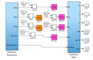
Figure 3: Quadrotor system controlled by the PD plus integral controllers
However, it is worth noticing that the choice of the membership functions degree significantly affects the necessary computational time for designing the controller. This means that choosing a small MFs degree is beneficial to the controller computing time. Then, in the proposed ANFIS controller, only three inputs MFs and three output MFs, are configured to implement each fuzzy inference system (FIS) of the controller. Furthermore, compared to other MFs types such as the trapezoidal, triangular, and bell, the Gaussian MFs type is characterized by the less complexity and high precision (see e.g. [30], and [31]). Thus, the (Gaussian) MFs that are chosen as inputs MFs type are defined by:
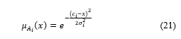
where , are the center(width) of the fuzzy set for each MF. Finally, the other inference parameters are chosen as shown in Table 1:
Table 1: Inference system parameters
| Fuzzy type | Defuzzification method | Inference engine |
| Takagi-Sugeno | weighted average (wtaver) | prod-max |
Indeed, to design the ANFIS controller, we should select additional ANFIS parameters such as training epoch number , training error goal and optimization method. Practically, we used the parameter values that are given in Table 2.
Then, in quadrotor system control, the trained ANFIS controller is used instead of the above controllers (see Figure 3).
3.5. Integral control action for ANFIS controller
Each of the four resulting ANFIS controllers has two inputs (the error, and its derivative ) as shown in Figure 4. Then, the steady-state error cannot be removed because of the non-existence of internal integral control. For this reason, we associate each ANFIS controller with an integral control action to combine the benefits of the ANFIS controller and the integral control, which allows obtaining an enhanced and robust controller that is denoted
Table 2: ANFIS algorithm parameters
| Training epoch number | Training error goal | Optimization method |
| 20 | 0 | Last-squares and back-propagation gradient descent |
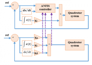
Figure 4: Selection of training data set for ANFIS controller
For this reason, two inputs of each initials controllers (error , and its rate ) are used to design the ANFIS controller while the integral action ( ) is maintained in the designed ANFIS controller with the same parameter . Thus, due to the additional integral control, the controller results in a multi closed-loop control structure, which permits obtaining better performance for the quadrotor control system [25].
Furthermore, to enhance the performance of the ANFIS+I controller, three inputs and output scaling gains are added as shown in Figure 5. Then suitable values should be determined for each scaling gain. Specifically, as three scaling parameters should be simultaneously tuned for each ANFIS+I state-controller, in the next subsection, the multidimensional particle swarm optimization (PSO) algorithm is proposed.
3.6. Multidimensional PSO algorithm description
Based on the observation of birds flying, the particle swarm optimization (PSO) metaheuristic algorithm was initiated by J. Kennedy and R. C. Eberhart in 1997 [32]. Thus, the theory of this algorithm is based on the arbitrary choice of particles to design the initial population in a fixed search space [16]. Then, at each new iteration, a different population is selected according to the position and velocity of each particle.
Therefore, as stated by the next equations, the best values of the local and global fitness parameters are computed as follows:
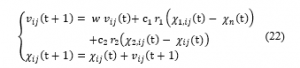
where denotes the particle number of populations, assigns the parameter to tune in dimension . and denote the cognitive and social constants, respectively. and are arbitrary scalars in the interval [0,1]. is the inertia weight that is used to balance the effect of the previous velocity to the actual value. Thus, at each specific time t, for each particle in each dimension several parameters are to consider: the velocity , the position , the local best fitness , and the global best fitness . Then, to design the four PSO-based ANFIS+I controller, a code was developed using Matlab Environment. The main steps of this code are presented in Algorithm 2.
| Algorithm 2: Multidimensional PSO algorithm steps |
| Result: Optimum parameters |
| Set the search space, the particles number n, the number of iteration niter;
Repeat: Generate a random population Evaluate the objective function Evaluate the local and global best fitness Compute the velocity and position of particles according to equation (22) Until the maximum number of iterations (niter) is reached |
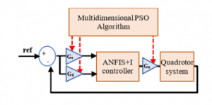
Figure 5: ANFIS+I controller scaling gains tuning using multidimensional PSO algorithm
The objective is to find the optimal values of the PSO-based ANFIS+I scaling gains for each controlled state ( and (see Figure 5). Then, the optimization algorithm starts by selecting the multidimensional PSO parameters such as the population number , the tune dimension , the maximum iterations number ( , and the search space.
In this work, to reduce the tuning dimension using the multidimensional PSO algorithm, we utilize the same PSO-based ANFIS+I controller for the horizontal position and as well, and for the attitude angle and as well, which permits simplifying the optimization dimension to three scaling factors and for only four ANFIS+I controllers. Thus, dimension could be reduced to twelve parameters. Besides, we choose 500 as the population number, 5 as the maximum number of iterations, and as bounds of the search space.
Then, the optimization process starts by initializing a random population , where ( represents a population particle, and ( denotes the number of tuned parameters. Then, at each iteration ( , the algorithm generates a new population after evaluating the best local and global fitness, which is based on computing two parameters: position and velocity of each particle according to equation (22). Of course, these computations are repeated until the
maximum of iteration number ( is reached and the smallest value of the objective function criterion is obtained. Thus, the algorithm ends and provides the suitable scaling gains that correspond to an optimal ANFIS+I controller.
3.7. Objective function criterion choice
As described in the above subsection, the multidimensional PSO algorithm role is to optimize the scaling gains of the (four) ANFIS+I controllers, which ends by obtaining a minimum value of an objective function criterion. For this reason, several criteria can be used such as the overshoot ( ), the settling time ( ), the rise time ( ) [20], the integral of absolute error ( ), the integral of squared error the integral of time-weighted squared error ( ), and the integral of time-weighted absolute error ( ) [33]. However, and objective function criteria do ignore the time when computing the difference between the desired signal and the actual signal (i.e, error e), which could result in high settling time and unacceptable overshoot [34], while and objective function criteria do compute the error through the time and allow improving the system performances.
Therefore, in this work, we use the well-known objective function criterion. Then, for each state, to evaluate the ANFIS+I scaling gains, we consider the ITAE criterion that is defined by:
4. Simulation Results
In this section, the simulation tests are provided to show the efficiency of the proposed PSO-based ANFIS+I controller. For clarity, the quadrotor system parameters are given in Table 3 [4].
To check the robustness of the proposed control strategy, four different controllers are implemented for controlling the quadrotor system.
Table 3: Quadrotor system parameters
| Symbol | Description | Value |
| g | Gravitational acceleration | 9.81 m.s-2 |
| m | Quadrotor mass | 0.65 Kg |
| l | Distance from center to motor | 0.23 m |
| jx | Moment of inertia about x-axis | 7.5 10-3 Kg.m2 |
| jy | Moment of inertia about y-axis | 7.5 10-3 Kg.m2 |
| jz | Moment of inertia about z-axis | 1.3 10-2 Kg.m2 |
| k | Propeller force constant | 3.13 10-5 N.s2 |
| d | Propeller torque constant | 7.5 10-7 N.s2 |
First, we collect the training data set that is used to design the fuzzy inference system. Thus, the first simulation scenario consists in controlling the quadrotor system by the classical PID control approach. For simplicity, for each quadrotor state ( , the suitable control parameters are determined using the Matlab PID Tuner. These parameters are summarized in Table 4.
Thereafter, the ANFIS controller is implemented using the data collected from the quadrotor system dynamic response when it is controlled by the PID control approach. In this step, an initial ANFIS controller is designed using the generated fuzzy inference system. Roughly, two MATLAB functions are available: genfis1, which returns the initial membership functions set, and anfis, which gives the fuzzy inference system.
Table 4: Parameters of PID controller
| 0.011 | -0.011 | 3.09 | 0.4 | 0.4 | 3.7 | |
| 0 | 0 | 1.5 | 0.15 | 0.15 | 7.5 | |
| 0.12 | -0.12 | 4.5 | 0.11 | 0.11 | 0.56 |
Then, to improve the ANFIS controller, we kept the initial integral control action in the designed controller, which allows guaranteeing more robustness to the closed-loop system.
In the next step, to improve the quadrotor control system performances, we use the multidimensional PSO algorithm to optimize the ANFIS+I scaling gains ( Table 5 gives the value of the obtained scaling gains for each quadrotor state after the optimization process.
Table 5: ANFIS+I scaling gains tuned by multidimensional PSO algorithm
| 4.82 | -4.82 | 2.21 | 4.56 | 4.56 | 4.26 | |
| 0.73 | -0.73 | 1.26 | 0.36 | 0.36 | 2.66 | |
| 4.4 | -4.4 | 2.31 | 0.95 | 0.95 | 2.21 |
For comparison purposes, Table 6 shows the performance results of the four control strategies: classical PID, ANFIS (without the integral control, (non-optimized) ANFIS+I, and multidimensional PSO-based ANFIS+I controllers.
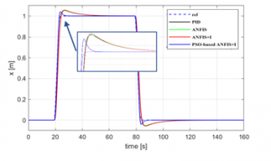
Figure 6: x-state tracking control response
Figures 6, 7, and 8 show the simulation results for x, y, and z quadrotor system states, respectively. The comparison of the four control strategies permits claiming that the PSO-based ANFIS+I controller can provide better control performances than the other control strategies. Except for the altitude (z) rise time, the proposed controller gives the smallest overshoot and the minimum rise and settling times.
For simplicity, the -yaw reference trajectory was chosen to be null. Then, from Figures 9, 10, and 11, it is shown that quadrotor Euler angles, namely ( , are very small, which means that the three quadrotor rotational motions are well stabilized.
Table 6: Performances of the PID, ANFIS, ANFIS+I, and PSO-based ANFIS+1
| PID | ANFIS | ANFIS+I | PSO-based ANFIS+I | ||
| 5.17 | 5.05 | 5.47 | 4.08 | ||
| 2.9 | 3.006 | 3.02 | 2.4 | ||
| 26.5 | 26.7 | 26.5 | 15.24 | ||
| 1.003 | 0.99 | 1.01 | 0.15 | ||
| 5.17 | 5.04 | 5.47 | 4.08 | ||
| 2.9 | 3.006 | 3.02 | 2.4 | ||
| 26.5 | 26.79 | 26.5 | 15.24 | ||
| 1.49 | 1.49 | 1.5 | 0.24 | ||
| 6.95 | 4.04 | 7.008 | 0.61 | ||
| 1.68 | 1.75 | 1.68 | 1.8 | ||
| 8.23 | 8.11 | 8.24 | 6.05 | ||
| 0.47 | 0.35 | 0.47 | 0.10 |
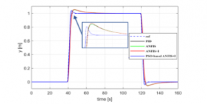
Figure 7: y-state tracking control response
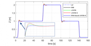
Figure 8: z-state tracking control response
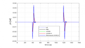
Figure 9: -state tracking control response
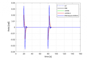
Figure 10: -state tracking control response
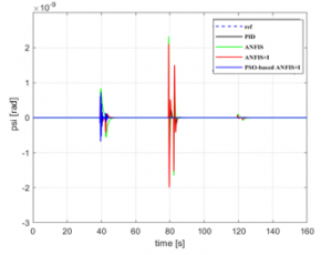
Figure 11: -state tracking control response
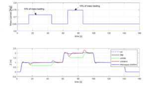
Figure 12: Mass payload disturbance rejection
Besides, additional simulation tests have been performed to evaluate the robustness of the proposed control strategy for the quadrotor system trajectory-tracking. Specifically, a payload mass has been added to the quadrotor system as an (unknown) external disturbance. Then, Figure 12 shows the effects on the quadrotor altitude z of 10% and 15% of total mass change, respectively. It is clearly shown that, in the case of the proposed controller, the fact
that the aerial vehicle’s total mass could be modified during the air travel has almost no effect upon the tracking quality. This means that the proposed controller can efficiently compensate for external static-like disturbances.
Then, from the above simulation examples, it results that the multi closed-loop PSO-based ANFIS+I control strategy can ensure the best control performances in comparison with the other control strategies, namely it generates the smallest overshoot and the smallest rise and settling times as well.
5. Conclusion
In this paper, a PSO-based adaptive neuro-fuzzy inference system plus integral (ANFIS+I) control is proposed as a new intelligent controller for the quadrotor trajectory tracking control problem. First, to collect the necessary training data set, a classical PID (tuned) controller is implemented for the quadrotor system. Then, to achieve good robustness, the (initial) integral control action is preserved in the control structure in addition to the generated ANFIS controller. Moreover, scaling gains are added to the ANFIS inputs-output, and optimized using the minimization of the objective function criterion. Thus, the new control strategy denoted multidimensional PSO-based ANFIS plus integral is designed. To show the effectiveness of the proposed controller, several simulation tests are provided. Namely, in comparison with the traditional PID, the ANFIS controller, ANFIS plus integral control, it is shown that the proposed control strategy can ensure better time-domain performances in case of trajectory tracking problem for the quadrotor system. Particularly, the proposed controller can efficiently compensate for unknown mass modification with the smallest overshoot and good attitude stabilization. Therefore, the multi closed-loop ANFIS+I controller, where the scaling gains are optimized using the multidimensional PSO-algorithm, can be considered as an additional control strategy to solve the position tracking problem for the quadrotor system.
- U.R. Mogili, B. Deepak, “Review on application of drone systems in precision agriculture,” Procedia Computer Science, 133, 502–509, 2018. doi:10.1016/j.procs.2018.07.063.
- E. Kaufman, K. Takami, Z. Ai, T. Lee, “Autonomous Quadrotor 3D Mapping and Exploration Using Exact Occupancy Probabilities,” in 2018 Second IEEE International Conference on Robotic Computing (IRC), IEEE: 49–55, 2018. doi:10.1109/IRC.2018.00016.
- X. Liang, Y. Fang, N. Sun, H. Lin, “Dynamics analysis and time-optimal motion planning for unmanned quadrotor transportation systems,” Mechatronics, 50, 16–29, 2018. doi: 10.1016/j.mechatronics.2018.01.009.
- S. Bouabdallah, Design and control of quadrotors with application to autonomous flying, Ph. D Thesis, Epfl, 2007.
- E. de Vries, K. Subbarao, “Backstepping based nested multi-loop control laws for a quadrotor,” in 2010 11th International Conference on Control Automation Robotics & Vision, IEEE: 1911–1916, 2010. doi: 10.1109/ICARCV.2010.5707890.
- S. Bouabdallah, R. Siegwart, “Full control of a quadrotor,” in 2007 IEEE/RSJ International Conference on Intelligent Robots and Systems, IEEE: 153–158, 2007. doi: 10.3929/ethz-a-010039365.
- A. Poultney, P. Gong, H. Ashrafiuon, “Integral backstepping control for trajectory and yaw motion tracking of quadrotors,” Robotica, 37(2), 300–320, 2019. doi: 10.1017/S0263574718001029.
- E. Chater, H. Housny, H. El Fadil, “Robust Control Design for Quadrotor Trajectory Path Tracking,” in 2019 8th International Conference on Systems and Control (ICSC), IEEE: 21–26, 2019. doi: 10.1109/ICSC47195.2019.8950509.
- J.F. Guerrero-Castellanos, N. Marchand, A. Hably, S. Lesecq, J. Delamare, “Bounded attitude control of rigid bodies: Real-time experimentation to a quadrotor mini-helicopter,” Control Engineering Practice, 19(8), 790–797, 2011. doi: 10.1016/j.conengprac.2011.04.004.
- M. Herrera, W. Chamorro, A.P. Gómez, O. Camacho, “Sliding mode control: An approach to control a quadrotor,” in 2015 Asia-Pacific Conference on Computer Aided System Engineering, IEEE: 314–319, 2015. doi: 10.1109/APCASE.2015.62.
- M. Huang, B. Xian, C. Diao, K. Yang, Y. Feng, “Adaptive tracking control of underactuated quadrotor unmanned aerial vehicles via backstepping,” in Proceedings of the 2010 American Control Conference, IEEE: 2076–2081, 2010. doi: 10.1109/ACC.2010.5531424.
- S.A. Raza, W. Gueaieb, “Fuzzy Logic based Quadrotor Flight Controller.,” ICINCO-ICSO, 9, 105–112, 2009.
- E. Kayacan, R. Maslim, “Type-2 fuzzy logic trajectory tracking control of quadrotor VTOL aircraft with elliptic membership functions,” IEEE/ASME Transactions on Mechatronics, 22(1), 339–348, 2016. doi: 10.1109/TMECH.2016.2614672.
- M. Santos, V. Lopez, F. Morata, “Intelligent fuzzy controller of a quadrotor,” in 2010 IEEE international conference on intelligent systems and knowledge engineering, IEEE: 141–146, 2010. doi: 10.1109/ISKE.2010.5680812.
- H. Housny, H. El Fadil, “New Deterministic Optimization Algorithm for Fuzzy Control Tuning Design of a Quadrotor,” in 2019 5th International Conference on Optimization and Applications (ICOA), IEEE: 1–6, 2019. doi: 10.1109/ICOA.2019.8727622.
- H. Housny, H. El Fadil, “Fuzzy PID Control Tuning Design Using Particle Swarm Optimization Algorithm for a Quadrotor,” in 2019 5th International Conference on Optimization and Applications (ICOA), IEEE: 1–6, 2019. doi: 10.1109/ICOA.2019.8727702.
- S. Bansal, A.K. Akametalu, F.J. Jiang, F. Laine, C.J. Tomlin, “Learning quadrotor dynamics using neural network for flight control,” in 2016 IEEE 55th Conference on Decision and Control (CDC), IEEE, Las Vegas, NV, USA: 4653–4660, 2016, doi:10.1109/CDC.2016.7798978.
- F. Soares, J. Burken, T. Marwala, “Neural network applications in advanced aircraft flight control system, a hybrid system, a flight test demonstration,” in International Conference on Neural Information Processing, Springer: 684–691, 2006. doi: 10.1007/11893295_75.
- A. Abraham, “Beyond integrated Neuro-fuzzy systems: reviews, prospects, perspectives and directions,” School of Computing and Information Technology, Monash University, Victoria, Australia, 2002.
- P. Ponce, A. Molina, I. Cayetano, J. Gallardo, H. Salcedo, J. Rodriguez, “Experimental Fuzzy Logic Controller Type 2 for a Quadrotor Optimized by ANFIS,” IFAC-PapersOnLine, 48(3), 2435–2441, 2015, doi:10.1016/j.ifacol.2015.06.453.
- S. Rezazadeh, M.A. Ardestani, P.S. Sadeghi, “Optimal attitude control of a quadrotor UAV using Adaptive Neuro-Fuzzy Inference System (ANFIS),” in The 3rd International Conference on Control, Instrumentation, and Automation, IEEE, Tehran, Iran: 219–223, 2013, doi:10.1109/ICCIAutom.2013.6912838.
- O. Ghorbanzadeh, H. Rostamzadeh, T. Blaschke, K. Gholaminia, J. Aryal, “A new GIS-based data mining technique using an adaptive neuro-fuzzy inference system (ANFIS) and k-fold cross-validation approach for land subsidence susceptibility mapping,” Natural Hazards, 94(2), 497–517, 2018, doi:10.1007/s11069-018-3449-y.
- H.M.I. Pousinho, J.P.S. Catalao, V.M.F. Mendes, “Wind power short-term prediction by a hybrid PSO-ANFIS approach,” in Melecon 2010-2010 15th IEEE Mediterranean Electrotechnical Conference, IEEE: 955–960, 2010. doi: 10.1109/MELCON.2010.5475923.
- J.P. da S. Catalão, H.M.I. Pousinho, V.M.F. Mendes, “Hybrid wavelet-PSO-ANFIS approach for short-term electricity prices forecasting,” IEEE Transactions on Power Systems, 26(1), 137–144, 2010. doi: 10.1109/TPWRS.2010.2049385.
- H. Housny, E. Chater, H. El Fadil, “Multi-Closed-Loop Design for Quadrotor path-Tracking Control,” in 2019 8th International Conference on Systems and Control (ICSC), IEEE: 27–32, 2019. doi: 10.1109/ICSC47195.2019.8950659.
- H. Housny, H. El Fadil, “PSO-based ANFIS for quadrotor system trajectory-tracking control,” in 2020 1st International Conference on Innovative Research in Applied Science, Engineering and Technology (IRASET), IEEE: 1–6, 2020. doi: 10.1109/ICSC47195.2019.8950659.
- R. Mahony, V. Kumar, P. Corke, “Multirotor Aerial Vehicles: Modeling, Estimation, and Control of Quadrotor,” IEEE Robotics Automation Magazine, 19(3), 20–32, 2012, doi:10.1109/MRA.2012.2206474.
- J.-S. Jang, “ANFIS: adaptive-network-based fuzzy inference system,” IEEE Transactions on Systems, Man, and Cybernetics, 23(3), 665–685, 1993. doi: 10.1109/21.256541.
- L.A. Zadeh, Fuzzy sets and applications, 1987.
- N. Talpur, M.N.M. Salleh, K. Hussain, “An investigation of membership functions on performance of ANFIS for solving classification problems,” IOP Conference Series: Materials Science and Engineering, 226, 012103, 2017, doi:10.1088/1757-899X/226/1/012103.
- A. Sadollah, Introductory Chapter: Which Membership Function is Appropriate in Fuzzy System?, InTech, 2018, doi:10.5772/intechopen.79552.
- J. Kennedy, R.C. Eberhart, “A discrete binary version of the particle swarm algorithm,” in 1997 IEEE International conference on systems, man, and cybernetics. Computational cybernetics and simulation, IEEE: 4104–4108, 1997. doi: 10.1109/ICSMC.1997.637339.
- T.K. Priyambodo, A. Dharmawan, O.A. Dhewa, N.A.S. Putro, “Optimizing control based on fine tune PID using ant colony logic for vertical moving control of UAV system,” in AIP Conference Proceedings, AIP Publishing: 170011, 2016. doi: 10.1063/1.4958613.
- R.A. Krohling, J.P. Rey, “Design of optimal disturbance rejection PID controllers using genetic algorithms,” IEEE Transactions on Evolutionary Computation, 5(1), 78–82, 2001. doi: 10.1109/4235.910467.