Development of the Surface Roughness Model in the Grinding Processes

Adv. Sci. Technol. Eng. Syst. J. 5(5), 1184–1188 (2020);
 DOI: 10.25046/aj0505143
This paper presents a research about the modelling of surface roughness in the grinding process. Based on the analyzed results about the surface roughness models from the previous studies, this study was performed to develop a surface roughness model in the grinding process. The surface roughness model is proposed with two hypotheses about the shape and ratio of the number of scratches of the grinding grains leaving on the workpiece surface. The first hypothesis is that the shapes of scratches of the grinding grains leave on the workpiece surface with five types including the triangle, the curved arc, the parabolic, the semi-circular, and the curved arc of a quarter circle. The second hypothesis is that the ratios of the number of the scratches with different shapes of the grinding grains leaving on the workpiece surface are the same (all are equal to 20%). This research paper discusses about the modelling of surface roughness when considering many shapes of scratches of the grinding grains left on the machining surface. This proposed model can be used to calculate the surface roughness in grinding processes of the different pairs of grinding wheels and workpieces. The developed surface roughness model has been applied to calculate the surface roughness during the grinding of SUJ2 steel using an aluminum oxide grinding wheel. Calculated surface roughness using proposed model were quite close to the experimental results. The average difference between calculated and the experimental results was about 14.84%. This study offers a promising ability to calculate the machining surface roughness in the grinding processes.
Nomenclature
– Cutting depth.
– Grinding wheel dressing depth.
– Grinding wheel width.
– Grinding grain concentration (for diamond and CBN grinding wheels).
– Equivalent diameter of grinding wheel.
– Diameter of the grinding grain.
– Grinding wheel diameter.
– Workpiece diameter.
– Expectation of the undeformed chip thickness.
– Expectation of the surface roughness.
– Undeformed chip thickness in grinding processes.
– Ratio of the part volume of particle (participated in the cutting processes) and the volume of particle.
– Contact length between the grinding wheel and the machining surface.
– Graininess of the grinding wheel (The number of sieve holes per square inch of the sieve).
– Number of dynamic cutting grinding particles per unit area of grinding wheel surface.
– Ratio between the length and the height of the chip.
– Structure number of the grinding wheel (for normal grinding wheel).
– Grinding wheel dressing feed rate.
– Plunge feed rate.
– Volume ratio of the grinding particles in the grinding wheel.
– Grinding wheel velocity.
– Workpiece velocity.
1. Introduction
Grinding method is one of the most common machining methods in the metal cutting processes. This method is often chosen as a finishing machining process to machine the surfaces with requirement of high dimension precision and high surface quality [1, 2].
Surface roughness has much influence on the working ability and the life of the mechanical products. So, the surface roughness is often selected as one of the most important factors to evaluate the efficiency of a grinding process. However, in the investigation of grinding surface roughness, the experimental method costs much time and money usually. Besides, this method is only applied to a few specific cases, the application ability of experimental results is the limitation [3] and [4].
The grinding surface roughness was modeled by different methods. In this study, the surface roughness models in the previous studies were analyzed, and then a new surface roughness model was developed to calculate the surface roughness in the grinding processes. The accuracy of the development surface roughness model has been validated through the experiments of grinding processes.
2. A brief review of some surface roughness models in the grinding processes
To overcome the limitations of the experimental methods, many studies were performed to model the grinding surface roughness by different methods. The surface roughness models were built depending on the parameters of the grinding processes as presented in the Table 1.
From the Table 1, it seems that the surface model was modeled by only considering the relationship between surface roughness and the workpiece velocity, grinding wheel velocity, the grinding wheel diameter, and the contact length between the grinding wheel and the machining surface [3]. In this model, the effect of characteristic parameters of grinding wheel such as the graininess of the grinding wheel, the structure number of the grinding wheel, etc. on the surface roughness has not mentioned. So, it is difficult to apply this model in different cases when using different grinding wheels.
In the model 2, the surface roughness was built depending on the velocity of workpiece and velocity of grinding wheel [5], [6]. In these studies, the effect of other parameters on the surface roughness was evaluated through the adjustment coefficients and the exponential number . So, to apply this model in the calculation of surface roughness, the experiments must be conducted to determine the values of the coefficients and . Similarly, to apply the model (3), the experiments must be performed to determine to coefficients and [7].
In the Table 2, some surface roughness models were presented based on the specific machining conditions. These models can be directly used to calculate the surface roughness. However, these models were only applied to calculate the surface roughness for the case the workpiece material, the grinding wheel types to be the same that one in the proposed research models.
Table 1: Surface roughness models – Type 1
| Source | Model | Note | No. |
| [3] | The surface roughness was built for surface grinding processes. | (1) | |
| [5] and [6] | and are the constants that depend on the machining conditions and can be determined by experimental method. | (2) | |
| [7] | and are the constants that depend on the machining conditions and can be determined by experimental method. | (3) |
Table 2: Surface roughness model – Type 2
| Source | Model | Grinding wheel | Workpiece | No. |
| [8] | 38A60K5VBE | 4140 steel | (4) | |
| [9] | HY-180x13x31.75-100# | C45 steel | (5) | |
| [10] and [11] | Where: | 2A80K4VFMB | AISI 52100 steel
|
(6) |
In the Table 3, the surface roughness models were built depending on the undeformed chip thickness and the adjustment coefficient (R). These models were built based on the theory of cutting processes in which these models did not depend on the specific machining conditions (grinding wheel types, workpiece materials, and so on). So, these models can be applied in a wider range than the above models. Besides, the undeformed chip thickness that has the relationship to the many parameters of the grinding processes including the cutting parameters, the grinding wheel geometry, etc. This relationship would be presented in the detail in the next sections.
Table 3: Surface roughness model – Type 3
| Models | Note | No. |
| , [4] | Hypothesis was that shapes of scratches of the grinding particles leaving on the workpiece surface was the triangle. | (7) |
| , [12] | Hypothesis was that shapes of the scratches of the grinding particles leaving on the workpiece surface was the curved arc. | (8) |
| , [13] | Hypothesis was that shapes of scratches of the grinding particles leaving on the workpiece surface was the parabolic. | (9) |
| , [14] | Hypothesis was that shapes of scratches of the grinding particles leaving on the workpiece surface was the semi-circular. | (10) |
| , [15] | Hypothesis was that shapes of scratches of the grinding particles leaving on the workpiece surface was the curved arc of a quarter circle. | (11) |
The above cited surface roughness models showed that depending on the different hypotheses about the shapes of the scratches of the grinding grains left on the workpiece surface. Few literatures were performed to confirm the exact shape of each of the scratches of the grinding grains left on the workpiece surface. It can be inferred that during the grinding processes, the geometry of the grinding grains is always changing (texture, form, self-dressing, and so on). These features on each cut of grinding grains left on the workpiece surface will always change. The shapes of scratches of the grinding grains left on the workpiece surface did not retain the shapes like that one in the hypotheses of the previous literatures. Hence, it is necessary to develop a surface roughness model considering the different shapes of scratches of the grinding grains left on the workpiece surface.
3. Developing a surface roughness model in grinding process
In this study, the surface roughness modelling was performed for grinding processes. The surface roughness model was built with two hypotheses as following:
The first hypothesis is that the shapes of the scratches of the grinding grain left on the workpiece surface are of five types such as triangle, curved arc, parabolic, semi-circular, and curved arc of a quarter circle.
The second hypothesis is that the ratios of the number of the scratches with different shapes of the grinding grains leaving on the workpiece surface are the same (all are equal to 20%).
Basing on above two hypotheses and the analyzed results from Table 3, the surface model that was proposed in this study as presented by (12).
![]()
Where – The expectation of the surface roughness.
– The expectation of thickness of undeformed chip.
The undeformed chip thickness has been mentioned in many studies. However, to present of this study in detail and clearly, the undeformed chip thickness was determined as following: According to reference [16], the undeformed chip thickness ( ) that was calculated by (13) and (14).
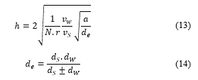
According to reference [17], it was difficult to determine the value of “r”, that was selected in the range from 10 to 20. In this study, the value of “r” was chosen by 20 (selecting according to previous studies [18] and [19]).
According to reference [19], the value of “N” that was determined by (15).
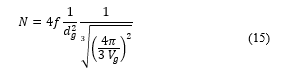
According to reference [18], it was also difficult to determine the value of “f”. In almost case, it can be assumed that half of a grinding grain that participated in cutting process. It means that .
is diameter of grinding grain that was determined from (16) to (18).
![]()
The value of was selected depending on the grinding wheel structure number . With common grinding wheel, the structure number is from 0 to 16, the value of is determined by (17) which means if the structure number increases one time, the volume of the grinding particles in the grinding wheel decreases 2%. According to reference [3] the maximum value of does not exceed 60%.
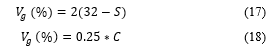
For the cases of the diamond and CBN grinding wheels, is determined according to the sign of the grinding particle concentration as listed in Table 4, [20]. From this table, for the diamond and CBN grinding wheels, the grinding particle concentration was determined by (18).
Table 4: The of several diamond and CBN grinding wheel [20]
| Concentration sign, C | 25 | 50 | 75 | 100 | 125 | 150 | 175 | 200 |
| ) | 6.25 | 12.50 | 18.75 | 25.00 | 31.25 | 37.50 | 43.75 | 50.00 |
From the (12) to (18), the surface roughness can be calculated by the block diagram with the parameters of the grinding process ( , , , , , , , , và ) as shown in the Figure 1.
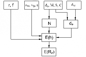
Figure 1: Block diagram of surface roughness calculation
4. Validation of the developed surface roughness model
The SG-5010AHR surface grinding machine was used to perform the experiments (Figure 2). The experimental workpiece was steel SUJ2 with the dimensions: length of 80 mm, width 40 mm, and height of 10 mm (Figure 3). This steel is often chosen for the fabrication of parts with high precision and surface gloss such as bearings, mold guide shafts, gears, etc. This study used an aluminum oxide grinding wheel with the symbol Cn100GV1x250x30x75x35m/s. This grinding wheel was produced by Hai Duong Grinding Stone Company (Viet Nam).
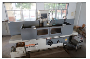
Figure 2: Experimental machine
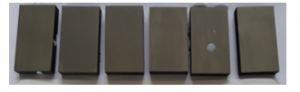
Figure 3: Experimental workpieces (SUJ2 steel)
In experimental method, 6 experiments were performed with the change of depth of cut, and 6 experiments were performed with the change of the workpiece velocity. Before each experiment, grinding wheel was dressed with a dressing depth of 0.01 mm and the dressing feed rate of 150 mm/min, respectively. Surface roughness SJ-210 tester was used to measure surface roughness (Ra) of the product. The basic parameters of this measuring equipment are shown in Table 5. And then, the measured results were used to compare to the calculated results by using proposed model of surface roughness. The compared results were described in Figure 4 and Figure 5. Figure 4 showed the surface roughness when calculating and measuring with varying depth of cut. For example: with point 6 in Figure 4: when the depth of cut is 10 (µm), the surface roughness when measuring and calculating are 1.92 (µm) and 1.57 (µm), respectively. Figure 5 showed the calculated surface roughness and the measured surface roughness when changing the workpiece velocity. For example: with point 11 in Figure 5: when the workpiece velocity is 11 (m/min), the surface roughness in the measurement and calculation are 1.42 (µm) and 1.72 (µm), respectively.
Table 5: Parameter of SJ301 surface tester (Mitutoyo – Japan)
| Model | SJ-301 |
| Trademark | Mitutoyo |
| Display | Touch screen and integration printer |
| Monitor | 14.5cm (5.7 inch) |
| Cable length | 1 m |
| Measurement method | Induction method |
| Sliding radius | 40 mm |
| Measurement force | 0.75 mN |
| Interface port | RS-232 C |
| Resistance wear standard | EN ISO, VDA, ANSI, JIS |
| Digital filter | 2RC -75%, 2RC -75% |
| Auto rest | after 5 minutes |
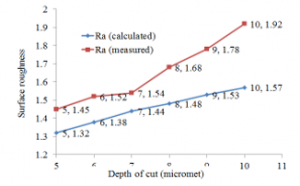
Figure 4: Measured and calculated surface roughness with the change of the cutting depth
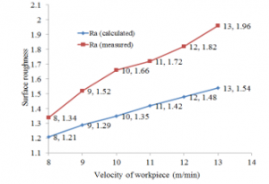
Figure 5: Measured and calculated surface roughness with the change of the workpiece velocity
The results of Figures 4 and Figures 5 illustrates that by using proposed model, the calculated and experimental results were quite close to each other. The average difference between the calculated and experimental results was 11.51% considering the depth of cut and 18.18 % for change in the velocity. The average difference between the calculated and experimental results was 14.84% for all cases.
5. Conclusion
The conclusion of this paper was drawn based on the investigation:
– A new model of surface roughness has been proposed considering different shapes of abrasive cuts left on the surface of the workpiece.
– The evaluation of the proposed surface roughness model in this study was carried out when grinding the SUJ2 steel using the aluminum oxide grinding wheel. The results inferred that the calculated surface roughness was quite close to the experimental.
In addition, the parameters of grinding wheel dressing mode, cooling lubrication parameters, and others also considered in the surface roughness model will be implemented in the further research.
Acknowledgment
The authors thank for support from Hanoi University of Industry (https://www.haui.edu.vn) in the experimental research.
- O. Kazuhito, T. Kazuya, A. Tomoya, T. Shinya, “Quick On-Machine Measurement of Ground Surface Finish Avaiable for Mass Production Cylindrical Grinding Process,” International Journal of Automation Technology, 9(2), 176-183, 2015, doi:https://doi.org/10.20965/ijat.2015.p0176
- L. Tao, D. Zhaohui, L. Lishu, S. Shuailong, L. Wei, L. Chengyao, “Experimental Analysis of Process Parameter Effects on Vibrations in the High-Speed Grinding of a Camshaft,” Strojniški vestnik – Journal of Mechanical Engineering, 66(3), 175-183, 2020.
- M. Stephen, G. Changsheng, Grinding technology theory and applications of machining with abrasives, Insustrial press, New York. 2008.
- L.R. Hecker, Y.L. Steven, “Predictive modeling of surface roughness in grinding,” International Journal of Machine Tools and Manufacture, 43, 755-761, 2003, doi:https://doi.org/10.1016/S0890-6955(03)00055-5
- R. Snoeys, J. Peters, and A. Decneut, “The Significance of Chip Thickness in Grinding,” Annals of the CIRP, 23, 227-237, 1974.
- S.M. Kedrov, “Investigation of Surface Finish in Cylindrical Grinding Operations,” Machines and Tooling, 51(1), 40-45, 1980.
- S. Akram, B. Robert, W. Andrew, “Investigation of single-point dressing overlap ratio and diamond-roll dressing interference angle on surface roughness in grinding,” Transactions of the Canadian Society for Mechanical Engineering, 34(2), 295-308, 2010.
- C.W. Lee, T. Choi, and Y.C. Shin, “Intelligent Model-based optimisation of the surface grinding process for heat treated 4140 steel alloys with Aluminium oxide grinding wheels,” Journal of Manu-facturing an Engineering, 125, 65-76, 2003, doi:10.1115/1.1537738
- V.T. Nguyen, D.T. Do, H.K. Le, H.A. Le, “Prediction of Surface Roughness When Surface Prediction of Surface Roughness When Surface,” Universal Journal of Mechanical Engineering, 8(2), 92-96, 2020, doi:10.13189/ujme.2020.080203
- R.P. Lindsay, R.P., and S. Hahn. “On the surface finish-metal removal relationship in precision grinding,” Annals of the CIRP, 95(3), 815–820, 1973, https://doi.org/10.1115/1.3438231
- X.M. Wen, A. A. O Tay, A. Y. C Nee, “Micro-Computer-based optimization of the surface grind-ing process,” Journal of Material Processing Technology, 29,75-90, 1992, doi:https://doi.org/10.1016/0924-0136(92)90426-S.
- A. Sanjay, P.V. Rao, “A probabilistic approach to predict surface roughness in ceramic grinding,” International Journal of Machine Tools & Manufacture, 45(6), 609–616, 2005, doi:https://doi.org/10.1016/j.ijmachtools.2004.10.005.
- A. Sanjay, P.V. Rao, “Surface roughness prediction model for ceramic grinding,” International Mechanical Engineering Congress and Exposition, 79180, 2005, doi:10.1115/IMECE2005-79180.
- K.K. Sanchit, A. Sanjay, “Predictive modeling of surface roughness in grinding,” CIRP Conference on Modelling of Machining Operations, 31, 375 – 380, 2015, doi:https://doi.org/10.1016/j.procir.2015.04.092.
- K.S. Krishna, A. Sanjay, D. Raj, “Surface Roughness Prediction in Grinding: A Probabilistic Approach,” MATEC Web of Conferences, 82(01019), 2016, doi:10.1051/matecconf/20168201019
- V.G. Anne, P.V. Rao, “A new chip-thickness model for performance assessment of silicon carbide grinding,” Int J Adv Manuf Technol, 24, 816–820, 2004, doi:https://doi.org/10.1007/s00170-003-1788-6.
- B.F. Nabil, S. Habib, B. Chedly, “Ground surface improvement of the austenitic stainless steel AISI304 using cryogenic cooling,” Surface & Coatings Technology, 200(16), 4846-4860, 2006, doi:https://doi.org/10.1016/j.surfcoat.2005.04.050
- J.E. Mayer. G.P. Fang, “Effect of grit depth of cut on strength of ground ceramics,” Annals CIRP, 43(1), 309-312, 1994, doi:https://doi.org/10.1016/S0007-8506(07)62220-3
- X. Hockin, S. Jahanmir, L.K. Ives, “Effect of grinding on strength of tetragonal zirconia and zirconia-toughned alumina,” Journal of Machining Science Technology, 1, 49-66, 1997, doi:https://doi.org/10.1080/10940349708945637
- https://www.noritake.co.jp/eng/catalog_type/download/8aa6080c86465c93cfebd53c07689c7f.pdf
No related articles were found.