Advanced Control Strategies on Nonlinear Testbench Dynamometer System for Simulating the Fuel Consumption

Adv. Sci. Technol. Eng. Syst. J. 5(5), 1172–1183 (2020);
 DOI: 10.25046/aj0505142
The adoption of Engine-in-the-loop technology shows real behaviour. This study presents a test runs simulation platform with real engine data. In addition, a test bench model is a demand approach that offers a significant potential to provide an excellent reproducibility of test runs. The platform includes the data integration to upgrade tests run and a comparison with previous results using the advancing control techniques designed. The dynamometer system presents significantly non-linearity. The adaptive control approach, integrated into the Model Predictive Control on the vehicle, allows increasing the tests run performance. The results show how the real data can improve performance and the validation of the system integrating the updated driving cycle and maintaining EiL approach. The conclusion showed the significant benefits regarding the control methods used.
1. Introduction
Nowadays, in automotive industries, analysis and testing of Electric Motors (EMs) and Internal Combustion Engines (ICEs) are the key elements. Accuracy and efficiency are further improved and allows to evaluate the vehicles’ production. However, to achieve these, the test benches are fundamentals. A novel data approach for advanced control strategies applied on a modelled test benches was introduced in a paper originally presented at the 23rd International Conference on System Theory, Control and Computing (ICSTCC) in 2019 [1], for which this work is an extension.
The tests are not limited to the EMs or ICEs in that the integration and combination of components are relevant. In the vehicles, brakes [2-4], energy management [5, 6], power devices [7, 8], sensors [9, 10], batteries [11-13], front steering [14, 15], are strongly analysed to increase vehicles’ performances. Every component needs to be tested determining robustness, reliability, fault-tolerant [16-21] and, in case of traditional and Mild Hybrid Electric Vehicles (MHEVs), the engine has to respect the limits and the restriction regarding fuel consumption and, consequently, emissions [22-25]. To reduce costs, the virtualisation and the introduction of simulation’s platform are included in the industry process [26, 27]. Considering the relevance of real data, in the last decade is introduced a new approach that includes the use of real components in the virtual tests. These techniques are called X-in-the-Loop (XiL) and include Engine-in-the-Loop, Hardware-in-the-Loop, Software-in-the-Loop, Model-in-the-Loop and Human-in-the-loop [28-32]. The XiL is used in different fields, as marine systems [33, 34], power units [36], home automation and robots [37], educational science [38].
Engine-in-the-Loop (EiL) techniques allow testing of the electric motors and internal combustion engines. EiL is widely used to ensure precision on testbench. This type of simulations allows to reduce simulation timing and to simulate testing scenarios leading to higher efficiency. Another significant benefit is the reduction of costs that this technology enables. The strengths of this approach include the adaptability of the system with different hardware and the reliability of the measured data deriving from the real engine. The EMs and the ICEs tested, most of the time, are prototypes [39, 40] and this excludes the possibility to have a reliable model of the EM or the ICE to be included in the simulation. The Eil technique allows the integration of EMs or ICEs, and it is significant in that the modelling of these demonstrates a different behaviour from the real. The solution is identified in the EiL approach [41, 42]. Based on that, the simulation and control of the Induction Motor (IM) on the testbench become essential, and to efficiency, the parametric model of IM must be identified. The overall model is affected by accuracy and nonlinear behaviour [43-45]. The partial linearization of the motor helps to define the real-non-linear behaviour. A first step of calibration is needed to assure proper performance. The introduction of control techniques in these systems increase precision and real-behaviour and point to manage tests easily. To guarantee reliability and security, final design and implementation of the control strategies are required. Generally, this phenomenon is described and controlled utilising methods to achieve more accurate results. An adaptive control leads to higher efficiency and performance compared to conventional control [46-49].
With the paper, the authors describe a possible solution to design an EiL architecture and an improvement of the control quality in a real environment. This paper aims to compare the results obtained, adding real-driving conditions and upgrading the driving cycles presented. The work is organised as follow: in the next paragraph (Background and review) is shown the background related to two critical elements that influence the automotive industry, the market and the legislation concerning driving cycles and the Engine-in-the-loop state of the art; in the third paragraph (Nonlinear system) the models of the testbench and others components are presented including a section with the calibration test; then the adaptive control strategies are introduced and integrate to the system to increase the robustness and dynamics (Control strategy). The results are presented in the Simulation and discussion paragraph that shows an adaptive control used in the simulation of the overall system in a real environment applied to the new driving cycles.
2. Background and review
In this section, the authors present a review about the background, including the market reasons that guided the choice of development and implemented a specific configuration model. In this section is introduced also the driving cycles used in the simulation for the validation of the system and includes an Engine-in-the-loop methods review.
2.1. Automotive Market
In the automotive market, electric motors have been introduced recently. In the industries, the most critical challenge is the reduction of carbon dioxide (CO2). The combination of engine and the electric motor in the vehicles guarantees excellent performance and the car’s production has adapted to the growing market. These represent a radical innovation in the industries and allowed an expansion of the market. The key challenges are:
- Complexity and reduction of costs
- Different market
- Virtualisation process
- Industries landscape
Based on these four points, it is clear that in the future, the changes are fast and in different directions [50, 51].
Nowadays, vehicles include a lot of components, and the complexity is growing. Nevertheless, the market requests the reduction of costs and lower price. For this reason, a solution developed with the introduction of new technologies and features is to enter in the electrification process. Thus, a conventional vehicle with ICE become a hybrid vehicle [52]. At the same time, are developing new systems and safety, and performances are increased. This electrification process is essential to the point of becoming an evaluation factor. However, the main challenge remains the costs reduction. The governments help to achieve this target with new stricter limits and regulations regarding the emissions and pollutants, and these restrictions reflect in differentiation of the markets [53]. The differentiation of the markets has developed the adaptability of the automotive industries that need to supply vehicles based on sales. To be competitive, the approach uses the virtualisation process [54, 55]. This process combines the connectivity with accessibility and increases the use of digital resources. The virtualisation is a potential technique and represents an opportunity applies to the driving experience. Another added value in the car is the communication and interaction. Besides, the development of new powertrain technologies and innovative solutions for active safety and infotainment change and it is based on the industry landscape. Europe needs to be reconstructed and adapt the capacity of industries; East Asia is a competitive emerging market. Each challenge is dependent and interconnected from the others and to capture future growth strategic choice, appropriate investments and resources are essential [56-58].
2.2. Driving Cycles development
The driving cycles are evolved and upgraded based on government and legislation of every countries and are founded on the market’s choices. The studied methodologies are not limited to the choice of driving cycles capable of making consumption real but include also to monitor energy consumption. An important aspect is the central role of driving cycles in emission measurement [59]. The pollutants, carbon dioxide, volatile organic compounds, nitrogen oxides and particulate are the results of the combustion of fuel and are regulated by countries directives. Emissions depend on different parameters and for this reason is classified based on vehicles types: cars, vans, buses, trucks and motorcycles.
In this paper, the authors illustrate driving cycles which had considered explicitly for the presented testbench. The driving cycles are described throughout some features shown in Table 1.
Table 1: Driving Cycles features
| Feature | Detail |
| Distance | Total distance |
| Time | Total time
Driving Time Acceleration Time Braking Time |
| Speed | Average Driving Speed
Minimum Speed Maximum Speed |
| Acceleration | Average Driving Acceleration
Minimum Acceleration Maximum Acceleration |
| Stops | Number of Stops
Average Stop duration |
The tests most used in the last ten years are:
- UDC or ECE-15: The Urban Driving Cycles represent a typical driving condition in Europe in a busy city with traffic and with a maximum speed of 50 km/h;
- EUDC: The Extra-Urban Driving Cycle is the high-speed road in the European cities with a maximum speed of 120 km/h;
- NEDC: The New European Driving Cycle is a combination of the UDC and EUDC, with four repetitions of UDC and once of EUDC;
- FTP-72 is the Federal Test Procedure used in US to simulate an urban road with multiple stops;
- FTP-75: Federal Test Procedure derived from FTP-72 is a city driving cycle with are a series of tests defined by the US Environmental Protection Agency (EPA),
- ARTEMIS Urban: is chassis dynamometer system procedure used in Europe with driving patterns derived from the analysis of a database containing real data and it is considered the urban track.
- ARTEMIS Rural: is chassis dynamometer system procedure as ARTEMIS Urban with the different that it is considered the rural road;
- ARTEMIS Motorway: as ARTEMIS Urban is chassis dynamometer system procedure and it is considered the motorway track.
These driving cycles are significant for new cars in that allow to test and know emission and pollutants. Lastly, as presented in the introduction, the validation tests assure that the results reflect real-world emission. This driving cycle is integrated into the system proposed in the following section to enhance the results on [1].
2.3. The engine in the loop
Engine-in-the-loop is a recent technique that makes possible to run a modelled testbench with an ICE reproducing the same conditions as when the engine is mounted in the real vehicle. Eil is a vehicle simulation linked and, in this technique, physical hardware called control unit, and an engine are integrated in a model of a testbench or a vehicle and driver model. The virtual testbench environment includes:
- High power
- Low inertia in the DSM
These perform a reasonable powertrain control and permit a detail emission evaluation.
The simulation of other components brings many benefits as repeatability and flexibility and can brush up the whole system. For this reason, the Eil approach results in an ideal choice for testbenches in that the accuracy, time-to-run and performance are highly improved [60, 61]. At the other hand, the request of this technique is the projecting of the entire system and for the high-speed real-time controller to have an adequate manage of the models implemented [62-66]. The fast response of the dynamometer loads the connected engine and the virtual vehicle follow the specific driving cycle target track as in the real world. Another influencer of the acceleration and speed is the vehicle pedal effect by the driver. In detail, the system includes an input-output behaviour deriving from the physical engine system and requests reasonable accuracy and response [67, 68]. The dynamics of the engine subsystem, along with the main subsystem testbench model and variables influence, is analysed to prevent fault. In automotive, the control strategy needs to be integrated into the control unit parameterising the whole virtual vehicle modelled and driveline configurations. The effects on the engine and performance are easily analysed as fuel consumption. In this use case, the relevant step is the calibration of the system in the virtualisation process and to reach a well-configurated testbench [69-71]. In automotive, the Eil is used during the development of new engine in that the testing of prototypes reduces the bugs and fastly improve the overall number. The development uses advanced simulation and modelling tools to realise a system with precise modelled functions that work together with physical hardware and processes. The virtualisation allows testing and validation of parameters and function guarantying highly quality [72-74]. However, several factors, as real-time computational complexity and calibration efforts, might lead to select faster and less-expensive techniques. The various combination and choice of vehicle calibration can limit in terms of management and testing functionalities, and the calibration steps must fit the engine behaviour. For these reasons and due to the architectural complexity of the Mild Hybrid Electric Vehicles, designing models for specific EM and ICE an adapt the entire system including interactions to the model is extremely difficult if even possible [75-77]. The major challenge is the satisfaction of the requirements during the Eil simulation.
3. Nonlinear system
The testbench detailed schema used in the present paper is shown in Figure 1. This collects some components: an inverter, the dynamometer motor (DSM) and the Device Under Test (DUT). On the EiL approach, the DUT could be an ICE (Internal Combustion Engine) or an EM (Electric Motor).
3.1. The Dynamometer System model
A general detailed model of the Dynamometer System is often too costly due to the induction machine typical non-linearity. Moreover, the parametrisation of the IM non-linearity is highly demanding for a standard automotive testbench commissioning process. Furthermore, the inverter includes a static controller with an unknown structure. The DSM is designed as a low-pass filter with fast dynamics with a simplified nonlinear mathematical model of DUT. The plant considered includes the inertia and the two parts of the testbench is treated as two mass oscillators. The model can be expressed as:
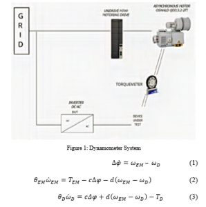
Figure 1: Dynamometer System
where:
EM is referred to DUT and can be consider as Engine or E-Motor,
D is applied to the dynamometer,
ωx is the speed,
θx the inertia,
∆φ the torsion of the shaft,
Tx the estimated or measured torque,
c is the stiff constant
d is the damping.
For run the testbench model, the first tread is the calibration of the system as explained in the next paragraph.
3.2. Calibration Process
The calibration plays a crucial role in a testbench. The parameters setting is often a necessary step which influences the tests. The calibration process is a signal that allows assessing the exact initial configuration. The computation is real-time for the DSM. Parameters in the first step are set with an offline estimation. Then, the torque signal starts with a fixed amplitude and increasing frequency, and it is evaluated the response. The previous calibration phase is repeated increasing magnitude and testing the new value of amplitude for every frequency. The online calculation provides time constant for the system. This dynamic calibration has been achieved considering the transfer function between reference torque and IM air gap torque and shaft speed. In a MIMO (Multiple Input Multiple Output) systems, a controller with low overshoot is significant for improving dynamics compensation and consider the different steady-state. Considering that the reference for the inverter is a torque signal, the test is run in the torque mode. This calibration process is essential for estimate the parameters, evaluate the results obtained, select the model parameters and helps to interpret the well-fit model flexibility. To assure a good fit the evaluation of the model is essential and there are many concepts to guarantee the single-best fit [78]. However, the authors choose to focus this paper on the Engine-in the loop approach and on the advanced control strategies applied.
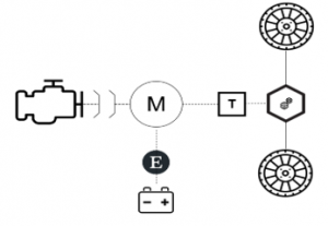
Figure 2: P2 Configuration: in order ICE, clutch, EM with Electronics and Battery pack, Transmission, Differential and Wheel.
3.3. P2 configuration
A testbench can simulate different types of ICE and EM; furthermore, the configuration of the vehicles can be changed, and this requires a different set of parameters and connected device. The structure considered is the parallel hybrid P2 of a Mild Hybrid Electric Vehicle. The P2 configuration is shown in figure 2. The EM (M) is placed in front of the transmission (T) and provide torque to compensate torque for dragging the ICE. The output torque derives from both ICE and EM. The vehicle can operate in pure electric mode, charge-battery mode, engine mode and parallel mode. Based on the way, the behaviours and the performances are different. In the designed testbench it is possible to test every way during a driving cycle. The virtual model of the vehicle implemented with the integration of the Eil techniques is shown in the next section.
3.4. Vehicle Model
Based on the virtual vehicle developed presented in [1], lateral and vertical dynamics are included. The analysis of the static and dynamic behaviour is necessary to have a stable model of the vehicle. A multitude of parameters influences the stability and a representation of the main components is required to have a reliable system. For define the static behaviour, the steady-state cornering equations are introduced. The yaw velocity defines the steady steady-state and the sideslip angle β that are constant.
For the steady-state case, the torque balance influenced by the front and the rear wheel is:
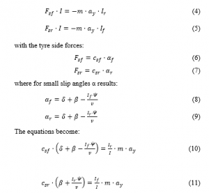
In the case of steady-state co
rnering, (10) and (11) are equal and the sideslip angle β are constant, so =0. The prediction of driving behaviour results:
![]()
And based on (12), considering that and
, the stationary yaw amplification factor can be written as:

where:
is the force
is side front
is side rear
is the inertia
is the mass of the vehicle
is the acceleration
is the yaw velocity
β is the sideslip angle
is the driving speed
is the stiffness of tyre slip
is the slip angle front or rear
is the wheel steering angle
is the instantaneous curve radius.
The static behaviour shows the output variable divide for input variable δ that represent the stationary yaw amplification factor (13) that is related to the driving speed . These equations are significant to define the vehicle’s model and its behaviour. An essential prediction about the driving behaviour of a car while cornering results from these equations. The necessary steering angle input while navigating around a corner is composed of two parts: one part depends on geometric data, and the second part describes the influence of lateral acceleration. Driving at higher speeds in addition to low rates necessary input steering angle includes the steering angles at higher speeds which can increase or reduce the steering angle. This is very important for the interactions between the driver inputs and vehicle handling in the driver and vehicle control loop. While cornering, the driver must input a steering angle, which depends on the curve radius, and the present lateral acceleration. The reason that the steering angles depend on the lateral acceleration is that at the vehicle wheels while experiencing lateral force, a slip angle results, which usually differ for the front and rear wheel.
3.5. Electric Motor and Battery
In a Mild Hybrid Electric Vehicle, the electric motor can work as motor or generator based on the situation. The model of an EM is composed by an electronics unit setting on torque control mode, the EM and a battery pack. However, there are some constraints in terms of nominal value and maximum value of speed and torque. The operating range of motors in the electric vehicles is directly linked to the battery capacity. The battery has an enhanced capacity, compared with conventional cars, and this increases the operating range and decreases the emissions.
4. Control strategy
To face the non-linearities of the system, the feedback is supervised by an Adaptive Model Predictive Controller (AMPC). Its aim is performing robustness and reliability. The thought control pattern permits to improve the performance of the vehicle under study and the testbench behaviour concerning dead time compensation typical of such complex system. The controller presented strategy is necessary to guarantee disturbances rejection modified by the nonlinear behaviour of the vehicle. The schema in fig. 3 represents the action of the AMPC controller. The torque reference is the input of the dynamometer system placed as input of the inertia model. The control loop process handles the action of driver and the vehicle reaction. Therefore, the steering behaviour in the single-track road is included in the response of the control vehicle as to the static behaviour.

Figure 3: Control schema
The implemented control follows the same strategy explained in [1]. The Kalman filter inside is implemented as:
![]()
where and are the discrete-time instant system state variables at k+1 and k respectively. is the control vector and A,B are the matrices that link the state variables at time k to k+1 and w is the weight at time k.
The equations for the online state estimation on MATLAB/Simulink are as follow. The state prediction uses the matrices that represent an optional extension for the system, which are linearised in a non-stationary operating point.
State prediction:
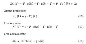
This implemented function generates the matrices used for the prediction. The adaptive controller executes in parallel an online Kalman Filter (KF) state estimator combined with a Least Square Algorithm (LS) for parameters estimation.
![]()
Based on the nonlinear state estimation model. The objective function is the minimisation of the weighted square of error.
![]()
The process includes:
- State update
- Update variance of the state error
- Gain matrix of the Kalman Filter
- Update estimation state, the variance disturb on state and loop.
In detail, the evaluated estimation of the target is adjusted for each time, and the parameters are evaluated until the fulfilled qualities are gained. The KF is utilised for the dead-time compensation of DSM. In the KF and the A(k) and B(k) lattice are updated each progression in the calculation by the LS. The controller is additionally adjusted by the online estimation of the parameter by the LS. The evaluation of disturbance with the dead-time compensation is critical to address the distortion and the non-linearity in the general model. The undesirable deformation and significant suppression of oscillations is accomplished utilising this methodology.
5. Simulations and discussions
To verify the proposed method, the DSM model and the controller is developed using the MathWorks Matlab/Simulink software. The preliminary outcomes obtained simulating the vehicle on the testbench is shown in [1]. Based on these previous results, the simulations are enhanced, adding the updated driving cycles presented in section 2.
Table 2: Use Case table
| Driving Cycle | Description | |||
| Time (s) | Distance (m) | Average Speed
(km/h) |
Fuel Consumption (gr CO2/km) | |
| NEDC | 1180 | 11023 | 33.6 | 47,49 |
| WLTP | 1477 | 23262 | 44.5 | 50,95 |
| FTP-72 | 1369 | 12070 | 31.5 | 52,81 |
| FTP-75 | 2474 | 17770 | 34.12 | 49,14 |
| ARTEMIS Urban | 993 | 4870 | 17.6 | 102,45 |
| ARTEMIS Rural | 1082 | 17272 | 57.5 | 32,48 |
| ARTEMIS Motorway | 1068 | 28735 | 96.9 | 16,74 |
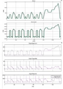
Figure 4: NEDC Cycle
Indeed, the AMPC performances exceed those of the conventional PID controller. Including the real-world disturbances on the vehicle, the PID controller no guarantees a fast, accurate response. For this reason, the authors test the considered driving cycles with AMPC controller by adding noise derived from the road.
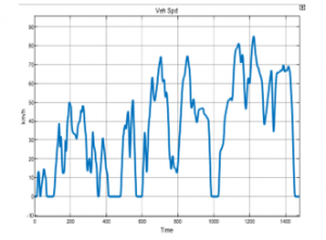
Figure 5: WLTP cycle
The torque request is based on the gas pedal value. The driving profiles are employed to examine the EiL test and to characterise the control system. Non-quantifiable amounts are assessed by filtering or with validated models. The AMPC controller results progressively strong, and the error is contained within 1.7 rpm to 2.8 rpm that is in the requirement of 3 rpm. This requirement derives from the possibility to measure not less than 3 rpm that results in the sensibility of the inverter. The error range is not changed, and this confirms and validates the control strategy. Every test procedure provides information about the behaviour of the control vehicle. Using Eil approach is important to maintain a defined speed minimum quantifiable with the physical process. The AMPC controls the reference quickly to the single setpoints while fulfilling the limitations. In the MHEVs this configuration is strongly used and the AMPC supply the ideal torque requested by the motor speed controller with more precision and control the values and references. The accuracy demonstrates through using AMPC improve the vehicle system and the reliable. The driving cycles are presented as a plot of the vehicle’s speed: NEDC ( Fig. 4), WLTP (Fig. 5), FTP-72 (Fig. 6), ARTEMIS Urban (Fig.7), Rural (Fig.8), Motorway (Fig.9). Furthermore, are shown the behaviour of electric motor modelled as motor or generator and the response of the engine, including the speed, the torque and the power. The description of every driving test cycle is in Table 2. The results are not only limited to the validation of the AMPC analysing the behaviour and the satisfaction of the requirements in that the emission for each test cycle is calculated. Table 2 shows the emission value for the driving cycles. The tests were chosen to cover a broad working range to investigate performance, and the controller results precise and accurate.

Figure 6: FTP-72 cycle
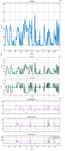
Figure 7: ARTEMIS Urban
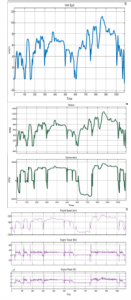
Figure 8: ARTEMIS Rural
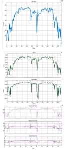
Figure 9: ARTEMIS Motorway
6. Conclusions and outlook
The results confirm the notable performances of the control strategy that allow characterising, with real feedback, the vehicles feature adding the disturbance to the road, a conventional control does not guarantee an accurate and fast response. Nevertheless, the AMPC disturbance rejection is strong, and the outcomes on the real system show excellent efficiency. This output is enhanced by measuring fuel consumption, and the results strongly validate the potential of this control strategy. Furthermore, the extension of driving cycles of the different country shows the R&R of the system. Overall, the research findings show that the nonlinear control strategies demonstrate outstanding disturbance rejection qualities. The flexibility of the testbench model can be investigated to find the single-best fit as the methods for assessing it. Moreover, these results can be extended to different vehicle’s configuration as P3 and P4 and full electric vehicles in order to improve systems efficiency.
- M. Fanesi, D. Scaradozzi, “Adaptive control for non-linear test bench dynamometer systems,” in 2019 23rd International Conference on System Theory, Control and Computing, ICSTCC 2019 – Proceedings, Institute of Electrical and Electronics Engineers Inc.: 768–773, 2019, doi:10.1109/ICSTCC.2019.8885558.
- J. Ko, S. Ko, H. Son, B. Yoo, J. Cheon, H. Kim, “Development of Brake System and Regenerative Braking Cooperative Control Algorithm for Automatic-Transmission-Based Hybrid Electric Vehicles,” IEEE Transactions on Vehicular Technology, 64(2), 431–440, 2015.
- F. Naseri, E. Farjah, T. Ghanbari, “An Efficient Regenerative Braking System Based on Battery/Supercapacitor for Electric, Hybrid, and Plug-In Hybrid Electric Vehicles With BLDC Motor,” IEEE Transactions on Vehicular Technology, 66(5), 3724–3738, 2017.
- S. Khastgir, “The simulation of a novel regenerative braking strategy on front axle for an unaltered mechanical braking system of a conventional vehicle converted into a hybrid vehicle,” in 2013 Eighth International Conference and Exhibition on Ecological Vehicles and Renewable Energies (EVER), 1–6, 2013.
- H. Wang, Y. Huang, A. Khajepour, “Cyber-Physical Control for Energy Management of Off-Road Vehicles With Hybrid Energy Storage Systems,” IEEE/ASME Transactions on Mechatronics, 23(6), 2609–2618, 2018.
- H. Fathabadi, “Plug-In Hybrid Electric Vehicles: Replacing Internal Combustion Engine With Clean and Renewable Energy Based Auxiliary Power Sources,” IEEE Transactions on Power Electronics, 33(11), 9611–9618, 2018, doi:10.1109/TPEL.2018.2797250.
- C. Sun, S.J. Moura, X. Hu, J.K. Hedrick, F. Sun, “Dynamic Traffic Feedback Data Enabled Energy Management in Plug-in Hybrid Electric Vehicles,” IEEE Transactions on Control Systems Technology, 23(3), 1075–1086, 2015, doi:10.1109/TCST.2014.2361294.
- Z. Amjadi, S.S. Williamson, “Power-Electronics-Based Solutions for Plug-in Hybrid Electric Vehicle Energy Storage and Management Systems,” IEEE Transactions on Industrial Electronics, 57(2), 608–616, 2010, doi:10.1109/TIE.2009.2032195.
- X. Li, Q. Xu, “A Reliable Fusion Positioning Strategy for Land Vehicles in GPS-Denied Environments Based on Low-Cost Sensors,” IEEE Transactions on Industrial Electronics, 64(4), 3205–3215, 2017, doi:10.1109/TIE.2016.2637306.
- S. Saponara, P. Tisserand, P. Chassard, D. Ton, “Design and Measurement of Integrated Converters for Belt-Driven Starter-Generator in 48 V Micro/Mild Hybrid Vehicles,” IEEE Transactions on Industry Applications, 53(4), 3936–3949, 2017, doi:10.1109/TIA.2017.2687406.
- R. Romagnoli, L.D. Couto, M.M. Nicotra, M. Kinnaert, E. Garone, “Computationally-efficient constrained control of the state-of-charge of a Li-ion battery cell,” in 2017 IEEE 56th Annual Conference on Decision and Control (CDC), 1433–1439, 2017, doi:10.1109/CDC.2017.8263855.
- J. Shen, A. Khaligh, “A Supervisory Energy Management Control Strategy in a Battery/Ultracapacitor Hybrid Energy Storage System,” IEEE Transactions on Transportation Electrification, 1(3), 223–231, 2015, doi:10.1109/TTE.2015.2464690.
- E. Kamal, L. Adouane, “Hierarchical Energy Optimization Strategy and Its Integrated Reliable Battery Fault Management for Hybrid Hydraulic-Electric Vehicle,” IEEE Transactions on Vehicular Technology, 67(5), 3740–3754, 2018, doi:10.1109/TVT.2018.2805353.
- S. Yim, J. Choi, K. Yi, “Coordinated Control of Hybrid 4WD Vehicles for Enhanced Maneuverability and Lateral Stability,” IEEE Transactions on Vehicular Technology, 61(4), 1946–1950, 2012, doi:10.1109/TVT.2012.2188921.
- S. Di Cairano, H.E. Tseng, D. Bernardini, A. Bemporad, “Vehicle Yaw Stability Control by Coordinated Active Front Steering and Differential Braking in the Tire Sideslip Angles Domain,” IEEE Transactions on Control Systems Technology, 21(4), 1236–1248, 2013, doi:10.1109/TCST.2012.2198886.
- A.H. Hajimiragha, C.A. Canizares, M.W. Fowler, S. Moazeni, A. Elkamel, “A Robust Optimization Approach for Planning the Transition to Plug-in Hybrid Electric Vehicles,” IEEE Transactions on Power Systems, 26(4), 2264–2274, 2011, doi:10.1109/TPWRS.2011.2108322.
- C. Quinn, D. Zimmerle, T.H. Bradley, “An Evaluation of State-of-Charge Limitations and Actuation Signal Energy Content on Plug-in Hybrid Electric Vehicle, Vehicle-to-Grid Reliability, and Economics,” IEEE Transactions on Smart Grid, 3(1), 483–491, 2012, doi:10.1109/TSG.2011.2168429.
- H. Yu, Z. Liu, “Fault Analysis and Fault-Tolerant Control of Electric Motor Drive System in HEV,” in 2012 Fifth International Conference on Intelligent Computation Technology and Automation, 177–180, 2012, doi:10.1109/ICICTA.2012.51.
- L. Zhang, Y. Fan, C. Li, C. Liu, “Design and Analysis of a New Six-Phase Fault-Tolerant Hybrid-Excitation Motor for Electric Vehicles,” IEEE Transactions on Magnetics, 51(11), 1–4, 2015, doi:10.1109/TMAG.2015.2447276.
- A. Berthon, F. Gustin, M. Bendjedia, J.M. Morelle, G. Coquery, “Inverter components reliability tests for hybrid electrical vehicles,” in 2009 IEEE 6th International Power Electronics and Motion Control Conference, 763–768, 2009, doi:10.1109/IPEMC.2009.5157487.
- A. Drosu, G. Suciu, A. Scheianu, I. Petre, “An Analysis of Hybrid/Electric Vehicle Monitoring Systems and Parameters,” in 2019 Electric Vehicles International Conference (EV), 1–5, 2019, doi:10.1109/EV.2019.8892923.
- Y. Cheng, C. Lai, J. Teh, “Application of Particle Swarm Optimization to Design Control Strategy Parameters of Parallel Hybrid Electric Vehicle with Fuel Economy and Low Emission,” in 2018 International Symposium on Computer, Consumer and Control (IS3C), 342–345, 2018, doi:10.1109/IS3C.2018.00093.
- S.A. Zulkifli, S. Mohd, N. Saad, A.R.A. Aziz, “Influence of motor size and efficiency on acceleration, fuel economy and emissions of split-parallel hybrid electric vehicle,” in 2013 IEEE Symposium on Industrial Electronics Applications, 126–131, 2013, doi:10.1109/ISIEA.2013.6738981.
- S.A. Rahman, Nong Zhang, Jianguo Zhu, “A comparison on fuel economy and emissions for conventional hybrid electric vehicles and the UTS plug-in hybrid electric vehicle,” in 2010 The 2nd International Conference on Computer and Automation Engineering (ICCAE), 20–25, 2010, doi:10.1109/ICCAE.2010.5451533.
- A.Y. Saber, G.K. Venayagamoorthy, “Plug-in Vehicles and Renewable Energy Sources for Cost and Emission Reductions,” IEEE Transactions on Industrial Electronics, 58(4), 1229–1238, 2011, doi:10.1109/TIE.2010.2047828.
- C.M. Martinez, X. Hu, D. Cao, E. Velenis, B. Gao, M. Wellers, “Energy Management in Plug-in Hybrid Electric Vehicles: Recent Progress and a Connected Vehicles Perspective,” IEEE Transactions on Vehicular Technology, 66(6), 4534–4549, 2017, doi:10.1109/TVT.2016.2582721.
- V. Delafosse, S. Stanton, T. Sekisue, Junsik Yun, “A methodology to use simulation at every stage of a hybrid vehicle design,” in 2012 IEEE Vehicle Power and Propulsion Conference, 1134–1138, 2012, doi:10.1109/VPPC.2012.6422618.
- H. Zhang, Y. Zhang, C. Yin, “Hardware-in-the-Loop Simulation of Robust Mode Transition Control for a Series–Parallel Hybrid Electric Vehicle,” IEEE Transactions on Vehicular Technology, 65(3), 1059–1069, 2016, doi:10.1109/TVT.2015.2486558.
- Zheng Li, Zetao Ma, Shumei Cui, “Design and research on engine emulation system of HEV power train hardware-in-the-loop simulation platform,” in 2014 IEEE Conference and Expo Transportation Electrification Asia-Pacific (ITEC Asia-Pacific), 1–6, 2014, doi:10.1109/ITEC-AP.2014.6941031.
- N. Shidore, A. Ickes, T. Wallner, A. Rousseau, M. Ehsani, “Evaluation of ethanol blends for PHEVs using engine-in-the-loop,” in 2011 IEEE Vehicle Power and Propulsion Conference, 1–8, 2011, doi:10.1109/VPPC.2011.6043041.
- Wang Lei, Yang Yalian, Peng Zhiyuan, Yang Guo, Hu Xiaosong, “Research on hybrid electrical vehicle based on human-in-the-loop simulation,” in 2014 IEEE Conference and Expo Transportation Electrification Asia-Pacific (ITEC Asia-Pacific), 1–5, 2014, doi:10.1109/ITEC-AP.2014.6940738.
- Wu Kai, Zhang Tong, Zhu Maotao, Zhou Jianhao, “Hardware-in-the-loop simulation for multi-energy management controller of Hybrid Electric Vehicle in a virtual car environment,” in 2011 International Conference on Electric Information and Control Engineering, 5061–5064, 2011, doi:10.1109/ICEICE.2011.5776933.
- J. Zhou, G. Ouyang, M. Wang, “Hardware-in-the-Loop Testing of Electronically-Controlled Common-Rail Systems for Marine Diesel Engine,” in 2010 International Conference on Intelligent Computation Technology and Automation, 421–424, 2010, doi:10.1109/ICICTA.2010.40.
- Y. Liu, M. Steurer, P. Ribeiro, “A novel approach to power quality assessment: real time hardware-in-the-loop test bed,” IEEE Transactions on Power Delivery, 20(2), 1200–1201, 2005, doi:10.1109/TPWRD.2005.844251.
- J. Wang, H. Lee, J. Wang, C. Lin, “Robust Environmental Sound Recognition for Home Automation,” IEEE Transactions on Automation Science and Engineering, 5(1), 25–31, 2008, doi:10.1109/TASE.2007.911680.
- A.M. Pavan, S. Castellan, G. Sulligoi, “An innovative photovoltaic field simulator for hardware-in-the-loop test of power conditioning units,” in 2009 International Conference on Clean Electrical Power, 41–45, 2009, doi:10.1109/ICCEP.2009.5212086.
- J. Domaszewicz, S. Lalis, A. Pruszkowski, M. Koutsoubelias, T. Tajmajer, N. Grigoropoulos, M. Nati, A. Gluhak, “Soft Actuation: Smart Home and Office with Human-in-the-Loop,” IEEE Pervasive Computing, 15(1), 48–56, 2016, doi:10.1109/MPRV.2016.5.
- M. Karakose, “Hardware, software, and human in the loop education supported with social network analysis and mining,” in 2016 15th International Conference on Information Technology Based Higher Education and Training (ITHET), 1–5, 2016, doi:10.1109/ITHET.2016.7760721.
- M. Hafner, T. Finken, M. Felden, K. Hameyer, “Automated Virtual Prototyping of Permanent Magnet Synchronous Machines for HEVs,” IEEE Transactions on Magnetics, 47(5), 1018–1021, 2011, doi:10.1109/TMAG.2010.2091675.
- X. Zeng, S. Zheng, D. Song, “Modeling and dynamic simulation of a virtual prototype for applying automobile differential into hybrid electric vehicle as power-slit device,” in 2010 International Conference on Computer Application and System Modeling (ICCASM 2010), V3-82-V3-87, 2010, doi:10.1109/ICCASM.2010.5620147.
- R.S. Vadamalu, C. Beidl, “Explicit MPC PHEV energy management using Markov chain based predictor: Development and validation at Engine-In-The-Loop testbed,” in 2016 European Control Conference (ECC), 453–458, 2016, doi:10.1109/ECC.2016.7810326.
- Y. Kim, A. Salvi, A.G. Stefanopoulou, T. Ersal, “Reducing Soot Emissions in a Diesel Series Hybrid Electric Vehicle Using a Power Rate Constraint Map,” IEEE Transactions on Vehicular Technology, 64(1), 2–12, 2015, doi:10.1109/TVT.2014.2321346.
- Liyong Yang, Xiaolin Peng, Zhengxi Li, “Induction motor electrical parameters identification using RLS estimation,” in 2010 International Conference on Mechanic Automation and Control Engineering, 3294–3297, 2010, doi:10.1109/MACE.2010.5535653.
- J. Xiaochun, Y. Geng, W. yunfei, “A Parameter Identification Method for General Inverter-fed Induction Motor Drive,” in 2006 CES/IEEE 5th International Power Electronics and Motion Control Conference, 1–5, 2006, doi:10.1109/IPEMC.2006.4778331.
- B. Zhu, K. Rajashekara, H. Kubo, “Comparison between current-based and flux/torque-based model predictive control methods for open-end winding induction motor drives,” IET Electric Power Applications, 11(8), 1397–1406, 2017, doi:10.1049/iet-epa.2016.0517.
- M. Pakmehr, T. Yucelen, “Adaptive control of uncertain systems with gain scheduled reference models and constrained control inputs,” in 2014 American Control Conference, 691–696, 2014, doi:10.1109/ACC.2014.6859326.
- D. Bourlis, J.A.M. Bleijs, “Gain scheduled controller with wind speed estimation via Kalman filtering for a stall regulated variable speed wind turbine,” in 2009 44th International Universities Power Engineering Conference (UPEC), 1–5, 2009.
- T. Ertuğrul, M.A. Adli, M.U. Salamci, “Model reference adaptive control design for helicopters using gain scheduled reference models,” in 2016 17th International Carpathian Control Conference (ICCC), 182–187, 2016, doi:10.1109/CarpathianCC.2016.7501090.
- E. Gruenbacher, L. del Re, “Robust inverse control for combustion engine test benches,” in 2008 American Control Conference, 2852–2857, 2008, doi:10.1109/ACC.2008.4586926.
- C. Yang, M. Zha, W. Wang, K. Liu, C. Xiang, “Efficient energy management strategy for hybrid electric vehicles/plug-in hybrid electric vehicles: review and recent advances under intelligent transportation system,” IET Intelligent Transport Systems, 14(7), 702–711, 2020, doi:10.1049/iet-its.2019.0606.
- J.E. Siegel, D.C. Erb, S.E. Sarma, “A Survey of the Connected Vehicle Landscape—Architectures, Enabling Technologies, Applications, and Development Areas,” IEEE Transactions on Intelligent Transportation Systems, 19(8), 2391–2406, 2018, doi:10.1109/TITS.2017.2749459.
- M. Traub, A. Maier, K.L. Barbehön, “Future Automotive Architecture and the Impact of IT Trends,” IEEE Software, 34(3), 27–32, 2017, doi:10.1109/MS.2017.69.
- T. Sivakumaran, F. Köhne, M. Toth, “Identification of critical success factors for emerging market entry planning processes in the automotive industry,” in 2015 IEEE International Conference on Industrial Engineering and Engineering Management (IEEM), 1694–1698, 2015, doi:10.1109/IEEM.2015.7385936.
- L. Hanwu et al., “Regularity of Current Dispersal in Different Kinds of Grounding Electrode,” in 2018 IEEE International Conference on High Voltage Engineering and Application (ICHVE), 1–4, 2018. doi: 10.1109/ICHVE.2018.8642240.
- A. Balluchi, L. Benvenuti, M.D. di Benedetto, C. Pinello, A.L. Sangiovanni-Vincentelli, “Automotive engine control and hybrid systems: challenges and opportunities,” Proceedings of the IEEE, 88(7), 888–912, 2000, doi:10.1109/5.871300.
- H. A. Raza et al., “Analysis the effect of 500kv High-Voltage Power Transmission Line on the Output Efficiency of Solar-Panels,” in 2019 International Conference on Electrical, Communication, and Computer Engineering, 1–6, 2019. doi: 10.1109/ICECCE47252.2019.8940803.
- A.R. Mahayadin, I. Ibrahim, I. Zunaidi, A.B. Shahriman, M.K. Faizi, M. Sahari, M.S.M. Hashim, M.A.M. Saad, M.S. Sarip, Z.M. Razlan, M.F.H. Rani, Z.M. Isa, N.S. Kamarrudin, A. Harun, Y. Nagaya, “Development of Driving Cycle Construction Methodology in Malaysia’s Urban Road System,” in 2018 International Conference on Computational Approach in Smart Systems Design and Applications (ICASSDA), 1–5, 2018, doi:10.1109/ICASSDA.2018.8477619.
- A. Charadsuksawat, Y. Laoonual, N. Chollacoop, “Comparative Study of Hybrid Electric Vehicle and Conventional Vehicle Under New European Driving Cycle and Bangkok Driving Cycle,” in 2018 IEEE Transportation Electrification Conference and Expo, Asia-Pacific (ITEC Asia-Pacific), 1–6, 2018, doi:10.1109/ITEC-AP.2018.8432599.
- A.R. Salisa, N. Zhang, J.G. Zhu, “A Comparative Analysis of Fuel Economy and Emissions Between a Conventional HEV and the UTS PHEV,” IEEE Transactions on Vehicular Technology, 60(1), 44–54, 2011, doi:10.1109/TVT.2010.2091156.
- J. Liu, L. Zhang, Q. Chen, S. Quan, R. Long, “Hardware-in-the-loop test bench for vehicle ACC system,” in 2017 Chinese Automation Congress (CAC), 1006–1011, 2017, doi:10.1109/CAC.2017.8242913.
- M.H. Salah, T.H. Mitchell, J.R. Wagner, D.M. Dawson, “A Smart Multiple-Loop Automotive Cooling System—Model, Control, and Experimental Study,” IEEE/ASME Transactions on Mechatronics, 15(1), 117–124, 2010, doi:10.1109/TMECH.2009.2019723.
- J. Zhao, J. Wang, “Adaptive Observer for Joint Estimation of Oxygen Fractions and Blend Level in Biodiesel Fueled Engines,” IEEE Transactions on Control Systems Technology, 23(1), 80–90, 2015, doi:10.1109/TCST.2014.2313003.
- A. Pratt, M. Ruth, D. Krishnamurthy, B. Sparn, M. Lunacek, W. Jones, S. Mittal, H. Wu, J. Marks, “Hardware-in-the-loop simulation of a distribution system with air conditioners under model predictive control,” in 2017 IEEE Power Energy Society General Meeting, 1–5, 2017, doi:10.1109/PESGM.2017.8273757.
- D. Michalek, C. Gehsat, R. Trapp, T. Bertram, “Hardware-in-the-loop-simulation of a vehicle climate controller with a combined HVAC and passenger compartment model,” in Proceedings, 2005 IEEE/ASME International Conference on Advanced Intelligent Mechatronics., 1065–1070, 2005, doi:10.1109/AIM.2005.1511151.
- S. Jiang, M. Smith, J. Kitchen, A. Ogawa, “Development of an Engine-in-the-loop Vehicle Simulation System in Engine Dynamometer Test Cell,” in SAE Technical Papers, 2009, doi:10.4271/2009-01-1039.
- T. Jung, M. Kötter, J. Schaub, C. Quérel, S. Thewes, H. Hadj-amor, M. Picard, S.-Y. Lee, Engine-in-the-Loop: A Method for Efficient Calibration and Virtual Testing of Advanced Diesel Powertrains: Antriebsentwicklung im digitalen Zeitalter 20. MTZ-Fachtagung, 209–224, 2019, doi:10.1007/978-3-658-25294-6_12.
- F.C. Nemtanu, I.M. Costea, D. Buretea, L.G. Obreja, “Hardware in the loop simulation platform for intelligent transport systems,” in 2017 IEEE 23rd International Symposium for Design and Technology in Electronic Packaging (SIITME), 247–250, 2017, doi:10.1109/SIITME.2017.8259901.
- R. Isermann, J. Schaffnit, S. Sinsel, “Hardware-in-the-Loop Simulation for the Design and Testing of Engine-Control Systems,” IFAC Proceedings Volumes, 31(4), 1–10, 1998, doi:https://doi.org/10.1016/S1474-6670(17)42125-2.
- M. Nasri, M. Kargahi, M. Mohaqeqi, “Scheduling of Accuracy-Constrained Real-Time Systems in Dynamic Environments,” IEEE Embedded Systems Letters, 4(3), 61–64, 2012, doi:10.1109/LES.2012.2195294.
- B.J. Bunker, M.A. Franchek, B.E. Thomason, “Robust multivariable control of an engine-dynamometer system,” IEEE Transactions on Control Systems Technology, 5(2), 189–199, 1997, doi:10.1109/87.556024.
- A. Ahmed et al., “Modeling and Simulation of Office Desk Illumination Using ZEMAX,” in 2019 International Conference on Electrical, Communication, and Computer Engineering (ICECCE), 1–6, 2019. DOI: 10.1109/ICECCE47252.2019.8940756.
- R. Jayaraman, A. Joshi, V. To, G. Kaid, “Fidelity Enhancement of Power-Split Hybrid Vehicle HIL (Hardware-in-the-Loop) Simulation by Integration with High Voltage Traction Battery Subsystem,” 2018, doi:10.4271/2018-01-0008.
- H. Holzmann, K. Hahn, J. Webb, O. Mies, “Simulation-Based ESC Homologation for Passenger Cars,” ATZ Worldwide, 114, 40–43, 2012, doi:10.1007/s38311-012-0218-5.
- U. Baake, K. Wüst, M. Maurer, A. Lutz, “Testing and simulation-based validation of ESP systems for vans,” ATZ Worldwide, 116, 30–35, 2014, doi:10.1007/s38311-014-0021-6.
- G. Siva Sankar, R. Shekhar, C. Manzie, T. Sano, H. Nakada, “Fast Calibration of a Robust Model Predictive Controller for Diesel Engine Airpath,” 2018.
- A. White, G. Zhu, J. Choi, “Hardware-in-the-Loop Simulation of Robust Gain-Scheduling Control of Port-Fuel-Injection Processes,” IEEE Transactions on Control Systems Technology, 19(6), 1433–1443, 2011, doi:10.1109/TCST.2010.2095420.
- H. Schuette, M. Ploeger, “Hardware-in-the-Loop Testing of Engine Control Units – A Technical Survey,” SAE Transactions, 116, 86–107, 2007.
- V.D. Veksler, C.W. Myers, K. Gluck, “Model flexibility analysis.,” Psychological Review, 122 4, 755–769, 2015.