Improvised E-Rickshaws for Indian Roads by Effective Battery-Ultracapacitor Hybridization

Adv. Sci. Technol. Eng. Syst. J. 5(5), 1162–1171 (2020);
 DOI: 10.25046/aj0505141
The revolution in the electrification of conventional vehicles due to increased petroleum prices and environmental concerns has had its impact on three-wheeler vehicles as well. Motorized three-wheeled vehicles, known as Auto-rickshaws, are a standard mode of trans- portation in India. Existing battery operated electric rickshaws (known as E-rickshaws) available in major cities of India faces challenges like insufficient charging facility, low driving range, high battery cost, battery replacement/disposal, etc. A battery-ultracapacitor (UC) hybrid energy source is proposed in this paper to overcome these issues. Two energy sources of complementary characteristics, when operated in tandem, can enhance the over- all performance of a vehicle in terms of weight, volume, and efficiency. An Erickshaw with battery-UC hybrid energy sources is modeled in Matlab-Simulink in this paper. The vehicle dynamics are calculated real-time based using a GPS based PerformanceBox tool of VBOX motorsport for Surat city. A fuzzy logic-based approach was employed for efficient energy management between these two sources with efficient utilization of regenerative power generated while braking. The system was later tested on Real-Time Hardware-in-Loop (HIL) environment to validate the simulation results. It was observed that the addition of an additional source with complementary characteristics had enhanced the performance of vehicle operation.
1. Introduction
Three wheeled motorized vehicles called as Auto-rickshaws, capable of carrying three to four passengers plays a vital role in public transportation in India along with trains and buses. Unlike city (with more than 4 million population) accommodates more than 50,000 auto-rickshaws [5] in India. That can account to 4-5% or sometimes even high as 10% of total vehicle population of a city. These vehicles can be a considerable source of air pollutants and is also a major customer of petroleum resources [6]. Electrification of auto-rickshaws can thereby lead to a better and cleaner mode of urban public transportation and can also urge the public to opt for them due to the improvisations in comfort, safety and cost to travel
[7].
Battery operated electric vehicles are gaining public and industry interest in the past couple of decades [8]. A battery operated auto-rickshaw (termed as E-rickshaw) was first introduced in the streets of New Delhi in 2010. Many researches on implementation of E-rickshaws/vehicles in different states and cities across the country and their economical and environmental impacts are available in literature. The technical and commercial issues hindering the popularity of electric vehicles in Pune was discussed in [9]. The merits, demerits and the challenges faced by adopting E-rickshaw as a possible mode for public transportation in the roads of West Bengal was discussed in [10]. A 24% fuel economy with hybridization and optimization was observed by [11] in their study on parallel electric hybrid E-rickshaws. A compact, robust and affordable hybrid system was developed and tested on a Bajaj RE auto-rickshaw by [12] and identified that the fuel consumption and CO2 emissions was significantly reduced by 21%.
There are many techno-commercial areas for improvisation in the design and development of E-rickshaws in India. Driving range is a major issue faced by e-rickshaws [13] along with waste management of used battery [14]. Another concern is method of power generation for charging batteries employed in E-rickshaws. One major aspect is the use of renewable energy for charging of the vehicle batteries which will lead to complete zero emissions [15]. Using conventional energy sources for electricity generation may result in zero tail-pipe emissions but will have less to no impact in global control of air pollution. Many literature is available on bonding renewable sources with electric vehicles. Incorporating solar energy as one of the energy source for electric vehicles and their economic impacts were studied in [16] and [17]. A correlative analysis study of a solar assisted three-wheeled rickshaw with various drive trains of hybrid configurations was carried out in [18]. A fuel cell based E-rickshaw which employs a fuzzy logic controller was proposed in [19]. In [20], a control scheme for solar rickshaw with maximum power point tracking algorithm (MPPT) was designed.
A rigorous review on various electrical energy storage technologies compatible for vehicular applications was carried out in [21] and [22]. The battery technologies available for electric vehicles including Li-ion batteries, lead acid batteries, Ni-MH batteries and ultracapacitors are discussed in [14]of which lithium-ion battery yields the lowest operating costs and GHG emissions (compared to lead-acid batteries). The research on lead-acid batteries, Li-ion batteries and ultracapacitor are gaining considerable significance in India as well [23]. Applications of different energy sources in Indian context was studied in [24]. Hybridization of energy sources with complementary characteristics to improve performance of electric vehicles [25] is attracting considerable interest these days. Hybridization of energy sources to achieve improved performance is been practiced in various applications [26, 27]. Hybridization enhances the performance of each sources involved, but with introducing complexity in its control. A study on possible methods for coupling a battery with an ultracapacitor for enhanced performance in electric vehicles was carried out in [28]. A study on different energy sources available for electric vehicles, their hybridization and energy management strategies was carried out in [29]. Performance improvement of a mild hybrid vehicle by hybridization of battery with ultracapacitor was suggested in [30].
Energy management between the hybrid sources employed in an electric vehicle calls for special care for ensuring optimum performance of both. The different control strategies viz. Rule based control strategy, Fuzzy rule based control strategy, Linear programming, Dynamic programming, Stochastic control strategy, Genetic algorithm, Particle swarm optimisation etc., for power split in a hybrid electric vehicle was discussed in [31]. A model predictive control strategy for sharing of power between a battery and ultracapacitor for a plug-in hybrid electric vehicle (PHEV) was proposed in [32] and has achieved significant improvement in performance. A data fusion approach for energy management in a fuel cell hybrid electric vehicle was proposed in [33]. The energy management strategy for a Fuel cell/Battery/Ultracapacitor hybrid electric vehicle is achieved by implementing an intelligent control technique constructed based on Fuzzy Logic Control (FLC) in [27]. A Fuzzy logic based energy management for a parallel hybrid electric vehicle was proposed by [34] considering torque demand and battery SOC as its inputs.
Presently, there is little to no work carried out in hybridization of energy sources in E-rickshaws in India which is the motivation for this work. In this paper the vehicle dynamics of an E-rickshaw is modeled in Matlab-Simulink for a standard Indian City Driving Cycle (IDC) which was calculated using a GPS based PerformanceBox tool of VBOX motorsport for Surat city. The system was later tested on a Real-time simulation environment to validate the results. The paper is divided into following sections. In section 2, the vehicle dynamics of an E-rickshaw is modeled to calculate the total tractive force. System architecture of an E-rickshaw is carried out in section 3 for a standard Indian City Driving Cycle (IDC). In section 4, the energy management between battery and ultracapacitor using a fuzzy logic based approach was discussed and the vehicle was tested for different driving conditions. The Matlab-Simulink simulation results are discussed in section 5 followed by a brief discussion on validation of the system implementation in Real-time environment in section 6. The paper concludes with discussions and conclusion in section 7.
2. Vehicle Dynamics of an E-rickshaw
The structure of a conventional auto-rickshaw is shown in Figure 2. The specifications of the auto-rickshaw is shown in Table 1 [12] whose parameters are taken as reference to design the E-rickshaw power-train.
Table 1: Specifications of Conventional Auto-rickshaw (Model: Bajaj RE 2S Petrol
| Specifications | Values |
| Gross vehicle weight, M | 610 Kg |
| Kerb weight | 272 Kg |
| Tyres, rw | 4.00-8, 4PR |
| Roll resistance, Cr | 0.015 |
| Air drag coefficient, Cd | 0.44 |
| Frontal surface area, Af | 2.0 m2 |
Load power requirement is calculated based on the drive cycle and vehicle dynamics. Energy source sizing is carried out based on this power requirement.
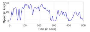
Figure 1: Indian City Drive Cycle (IDC) for Surat City
The drive cycle was calculated using a GPS based PerformanceBox tool of VBOX motorsport for Surat city and is chosen because the E-rickshaw is desired to be operated in cities. The load power requirement was calculated for the calculated standard Indian city driving cycle shown in Figure 1. Battery and ultracapacitor was sized based on this power requirements. Modeling of vehicle dynamics is explained in detail in the following sections.
2.1 Total Tractive force
The forces acting on a vehicle needs to be understood for an effective modeling of vehicle dynamics. The forces acting on an auto-rickshaw while hill climbing is shown in Figure 2. The tractive force generated by the electric motor of the vehicle has to experience and overcome these forces namely (a) Rolling resistance force (b) Aerodynamic drag (c) Grade resistance force and (d) Acceleration force [35].
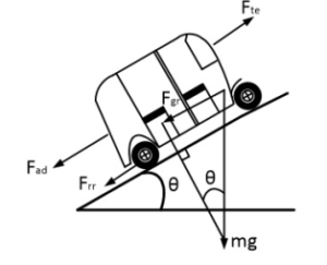
Figure 2: Forces acting on an auto-rickshaw moving along a slope
The major forces acting on an E-rickshaw and their expressions are shown in Table 2. Here, M is the mass of the vehicle in kg, g is the gravitational constant, i.e., 9.81 m/s2, Cr is the coefficient of rolling resistance, ρ is the air density in kg/m3, A is the frontal area of vehicle in m2, Cd is the drag coefficient, v is the velocity of the vehicle in m/s, θ is the clockwise angle made by the slope of the road with the horizontal plain and a is the acceleration of the vehicle in m/s2.
The total tractive force is the force required to propel the vehicle forward by overcoming all the above mentioned forces acting on the vehicle. Neglecting all other forces acting directly or indirectly on the vehicle, the total tractive force can be obtained from the Eq 1
Fte = Frr + Fad + Fgr + Faf (1)
3. E-rickshaw System Architecture
The sizing of every components like energy source,electric motor, power electronic converters etc., of an E-rickshaw depends on the vehicle parameters and driving patterns. The total tractive force required by the vehicle for propulsion was calculated using Eq 1.
System parameters like mass of the vehicle, frontal area etc., is available from Table 1. Vehicle velocity and acceleration is obtained from drive cycle data. Required load power is calculated as the product of total tractive force and velocity. The energy flow in a conventional electric-rickshaw is as shown in Figure 3. The vehicle dynamics of an auto-rickshaw is modeled in Matlab-Simulink environment.
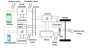
Figure 3: Energy flow diagram of an E-rickshaw with losses
The E-rickshaw is designed for the Indian City Drive Cycle (IDC) as shown in Figure 1 measured for a total time of 500 secs. The vehicle, being operated in the cities are desired to be run at a speed not more than 40 kmph due to the frequent starts and stops in traffic. The peak velocity is observed to be nearer at 38 kmph.
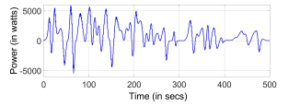
Figure 4: Load Power Requirement for Indian Drive Cycle (IDC)
The load power requirement for Indian City Drive Cycle (IDC) is shown in Figure 4. The peak power requirement was found to be approximately 5.0 kW. Considering the losses at each stages of transmission of power (source, converter and inverter), the required power to be provided by the E-rickshaw energy source was calculated. Assuming a constant source voltage of 48V (most of the E-rickshaws in India are operated with 48V Lead acid battery), the source current is calculated and is shown in Figure 5.
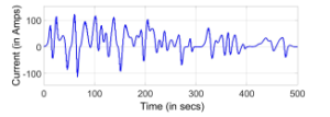
Figure 5: Source current for IDC
The proposed E-rickshaw is expected to have a driving range of
75 kms and the total distance travelled a day is expected to be 150 kms, there by calling for twice charging a day. The normal charging period is 2.5-3 hours. Figure 6 (a) shows the average speed at which E-rickshaw commutes inside a city. The vehicle covers a total distance of 2.548 kms at the end of 500 secs ( Figure 6 (b)) at an average speed of 18.3 kmph.
Table 2: Forces Acting on an E-rickshaw
|
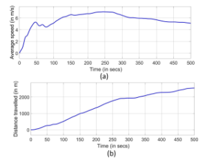
Figure 6: (a) Average Speed of an E-rickshaw (b) Total Distance travelled at the end of 500 secs
4. Fuzzy Logic based Energy Management
A fuzzy logic based approach for energy management was adopted in this paper due to its adaptive nature to the non-linear environment of electric vehicles. The source current shown in Figure 5, the battery and ultracapacitor state of charge (SOC) are taken as reference to split the energy requirement between battery and ultracapacitor for propelling the E-rickshaw as shown in Figure 7.
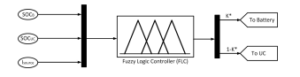
Figure 7: Fuzzy Logic controller
The three fundamental rules adopted for ensuring an optimum energy management was;
- Battery will be providing the average power requirements
(cruising).
- Ultracapacitor will be providing the peak power requirements (accelerating).
- Ultracapacitor will be absorbing the generated braking power which shall be followed by battery, if necessary (regenerative braking).
Battery, being a high energy density device is designed to provide the average power requirement and ultracapacitor is designed to provide the peak power requirement as it is a high power density device and can charge/discharge at a higher rate. The battery is designed not to discharge at more than 2C rate where C-rate is the rate at which a battery is discharged with respect to its maximum capacity. Based on the power requirements, the battery and ultracapacitor ratings are chosen as shown in Table 3
Table 3: Ratings of Battery and Ultracapacitor
| Function |
|
UC | |
| Type | Li-ion | Maxwell | |
| Rating | 48V, 20 AH | 48V, 165F | |
| Cell Specification | 3.7 V | 2.7 V | |
| Cell Combination | 13-series | 18-series | |
| Stored Energy | 960 Wh | 53 Wh | |
| Absolute Maximum
Current |
60 A | 1900 A | |
| Weight | 8 KG | 14.2 KG | |
| Charge temperature | -40 to 65◦C | 0 to 45◦C | |
| Discharge temperature | -40 to 65◦C | -20 to 60◦C |
4.1 Cruising mode of operation
When an E-rickshaw is running at a constant speed thereby consuming a non-varying power, the vehicle can be said to be in cruising or coasting mode of operation. The source current requirement will be average in this case whereby enabling the battery to supply the total power required (case-I; see Table 4). Depending on the state of charge (SOC) of battery and ultracapacitor, either of them is chosen for acting as the propelling power source of the vehicle (case-II). A threshold SOC of 20% is chosen for both battery and ultracapacitor for the state of health (SOH) concerns of both. Falling of SOC below the threshold value will alert the driver for an immediate stop of the vehicle and signals external plug-in charging of the battery (case-III). An average current of 17.6A was found to be drawn from the source during cruising mode of operation. Hence an upper threshold of 40A (considering 2C-rate of discharge) was set as the maximum possible current to be drawn from the battery.
4.2 Accelerating mode of operation
During acceleration the power requirement of the e-rickshaw will reach its peak thereby making the battery unable to supply the same.
IV
40 < i ≤ I XX 20% ≤ SOC ≤ 100% 0 1 V 40 < i ≤ I XX 0% ≤ SOC < 20% 0 0 VI i < 0 XX 0% ≤ SOC < 100% 0 1 Braking VII i < 0 0% ≤ SOC < 100% = 100% 1 0 VIII < 0 = 100% = 100% 0 0 |
Ultracapacitor (UC) hence will take care of the peak power requirements of the vehicle being a high power density device (case IV). The UC is designed based on the maximum current the device has to support (here approximately 120A) for a short duration of time.
The capacitance of UC is calculated using Eq 2.
![]()
where, dV is the change in voltage in volts i is the current in Amperes dt is the total discharge time in seconds and, R is the equivalent series resistance in ohms
The change in voltage is the desired maximum voltage drop of an ultracapacitor. Since 75% of energy in a UC gets consumed within 50% of terminal voltage drop, the change in voltage is kept as 24V (i.e., 50% of 48V). The total discharge time is kept equal to the vehicle test time i.e., 500 secs. Assuming the time constant RC=0.7, substituting for R in Eq 2 yields,
![]()
For an optimum calculation of capacitance of the ultracapacitor, the regenerative power gained during deceleration/braking is also considered. Hence the capacitance is calculated considering the average time and peak power requirement during the stages (acceleration/regenerative braking) it is needed by the vehicle. If the UC can no longer meet the power requirements of the vehicle (case-V), an external/internal charging of the same has to be done for efficient performance of the vehicle.
4.3 Regenerative Braking mode of operation
E-rickshaw, while decelerating/braking will be having a considerable amount of energy stored in it in the form of kinetic energy. In conventional vehicles this energy is wasted as heat energy in brake drums through mechanical braking as there is no provision to store it. In an E-rickshaw this energy can be stored in both battery and ultracapacitor with ultracapacitor being a more suitable choice due to its higher charge/discharge rate (case-VI). Battery cannot be exposed to higher currents for long time as it effects its state of health which makes it a lesser preferable choice for absorbing the regenerative braking power. Depending on the state of charge (SOC) of both battery and ultracapacitor, this recovered energy can be stored in either of them. If the UC is completely charged then the remaining regenerative power will be absorbed by battery depending on its SOC (case-VII). If both energy sources are fully charged and still there is a flow of regenerative power then it will be dissipated across the available mechanical brakes (case-VIII).
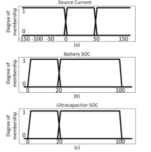
Figure 8: Membership functions for (a) Source current (b) Battery SOC and (c) Ultracapacitor SOC
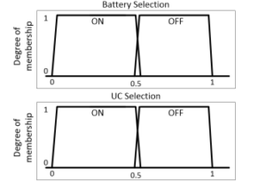
Figure 9: Membership functions for (a) Battery Selection and (b) Ultracapacitor Selection
The fuzzy rules set for an optimum energy management considering the efficient absorption of regenerative power is discussed in Table 4. The input membership functions of the fuzzy logic controller namely source current, battery SOC and ultracapacitor SOC are shown in Figure 8. The output membership functions for selection of energy sources are shown in Figure 9.
5. Simulation Results
Th vehicle has been tested in Matlab-Simulink environment for different conditions of battery and ultracapacitor. The results are discussed in detail below.
5.1 Case-I: Both Battery and UC fully charged (BattSOC=100% & UC-SOC=100%)
Both battery and ultracapacitor is assumed to be fully charged at start (i.e., Initial SOC = 100%). Depending on the power requirement, battery SOC and ultracapacitor SOC, the load power is shared between battery and ultracapacitor as shown in Figure 10.
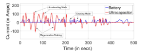
Figure 10: Case-I: Power split between Battery and UC
It is evident that during the cruising mode of operation battery is supplying the required power and during peak power requirement (accelerating mode) and while regenerative braking ultracapacitor supplies/absorbs power respectively.
The state of charge (SOC) of the battery and ultracapacitor is shown in Figure 11.
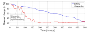
Figure 11: Case-I: Battery and UC SOC comparison
The terminal voltage characteristics (VT) of the battery and ultracapacitor when operated at Indian drive cycle is shown in Figure 12.
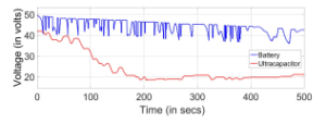
Figure 12: Case-I: Battery and UC Voltage (VT) comparison
The vehicle is able to operate during all three modes of driving i.e., cruising, accelerating and regenerative braking. During regenerative braking the ultracapacitor is being charged as shown in Figure 11. Battery is able to supply the required power for a longer duration when hybridized with an ultracapacitor when compared to operated alone thereby improving its state of health. Ultracapacitor has successfully absorbed the generated power during braking thereby improving vehicle performance and energy efficiency.
5.2 Case-II: Battery fully charged but UC less charged (Batt-SOC=100% & UC-SOC=25%)
Battery is assumed to be fully charged at start (i.e., Initial SOC = 100%) and ultracapacitor is assumed to be 75% discharged.
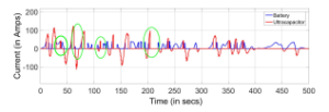
Figure 13: Case-II: Power split between Battery and UC
Depending on the power requirement, battery SOC and ultracapacitor SOC, the load power is shared between battery and ultracapacitor as shown in Figure 13 for a standard Indian drive cycle (IDC). During the cruising mode of operation battery is supplying the required power but during peak power requirement (accelerating mode) the ultracapacitor is unavailable to meet the system requirements once its SOC level reaches below 20% (see the highlighted areas in Figure 13). While regenerative braking, ultracapacitor absorbs power which is later used to meet the vehicle requirements while accelerating mode of operation. The state of charge (SOC) of the battery and ultracapacitor is shown in Figure 14.
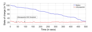
Figure 14: Case-II: Battery and UC SOC comparison
The terminal voltage characteristics (VT) of the battery and ultracapacitor is shown in Figure 15.Since the ultracapacitor is discharged already by 75%, its terminal voltage will be 24V, as the depth of discharge will be 75% in an ultracapacitor by the time its terminal voltage falls by half.
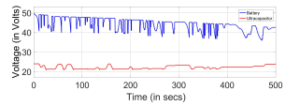
Figure 15: Case-II: Battery and UC Voltage (VT) comparison
The vehicle is able to operate only during cruising mode of driving. While accelerating the ultracapacitor is only able to meet the demands of the vehicle till its SOC reaches the bottom threshold of 20%. Once the SOC of the ultracapacitor falls below its lower threshold, the vehicle may no longer be able to accelerate thereby hindering its performance hugely. The driver may have to charge the ultracapacitor externally (Plug-In) or internally (through battery) to ensure smooth operation of the vehicle. Interestingly, during regenerative braking the ultracapacitor can still be charged as shown in Figure 14. Once the SOC level reaches above the lower threshold of 20% it can resume it duties and can contribute to the vehicle operation as before.
5.3 Case-III: UC fully charged but Battery less charged (Batt-SOC=25% & UC-SOC=100%)
Battery is assumed to be initially charged at 25% (i.e., Initial SOC = 25%) and ultracapacitor is assumed to be fully charged.
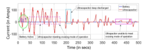
Figure 16: Case-III: Power split between Battery and UC
Depending on the power requirement, battery SOC and ultracapacitor SOC, the load power is shared between battery and ultracapacitor as shown in Figure 16.
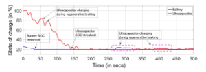
Figure 17: Case-III: Battery and UC SOC comparison
Since battery is very low charged, it cannot meet the vehicles’ demands after its SOC falls below the threshold value of 20%. Once the battery SOC is below 20% the ultracapacitor may continue to meet the vehicle average and peak demands till its SOC reaches 20% (see the highlighted areas in Figure 16). While regenerative braking, ultracapacitor absorbs power which is later used to meet the vehicle requirements during accelerating mode of operation. The state of charge (SOC) of the battery and ultracapacitor is shown in Figure 17.
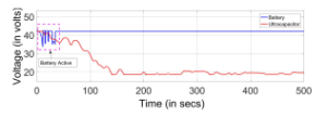
Figure 18: Case-III: Battery and UC Voltage (VT) comparison
The terminal voltage characteristics (VT) of the battery and ultracapacitor when operated at Indian drive cycle is shown in Figure 18. Since the battery is discharged already by 75%, its terminal voltage will be non-linearly reduced initially. The battery is active till its SOC reaches the lower threshold value. Once both the energy sources are below its lower threshold value of SOC, the driver has to perform an external charging of battery accompanied by an external (Plug-In) or internal (through battery) charging of ultracapacitor to ensure smooth operation of the vehicle. While regenerative braking, ultracapacitor absorbs power which is later used to meet the vehicle requirements during accelerating mode of operation.
6. Implementation Results
The proposed fuzzy logic based power-split between battery and ultracapacitor was experimentally tested in laboratory environment using the Xilinx made Spartan3 FPGA board (XC3S5000). A twochannel Agilent make DSO-X2002A is used to record the performance in real-time. The Indian city drive cycle generated from actual measured data is recreated in lab and is shown in Figure 19.
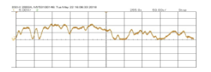
Figure 19: Real-time Indian City Drive Cycle at laboratory environment
The current to be drawn from the energy source(s) to meet the vehicle demands are shown in Figure 20.
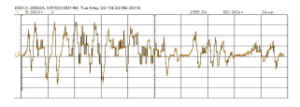
Figure 20: Source current requirement of E-rickshaw
The vehicle simulated in Matlab-Simulink was successfully recreated in a Real-time environment. The current drawn from the energy source for various modes of vehicle operation was observed to be closely matched with simulation results.
Al the three cases of vehicle operation based on battery and ultracapacitor state of charge (SOC) tested earlier with Matlab-Simulink was tested in laboratory environment. The results were found to be matching and is discussed briefly below.
6.1 Case-I: Both Battery and UC fully charged (BattSOC=100% & UC-SOC=100%)
Both battery and ultracapacitor is fully charged. As seen earlier, the vehicle is able to operate during all three modes of driving i.e., cruising, accelerating and regenerative braking. Ultracapacitor is being charged during regenerative braking as shown in Figure 21.
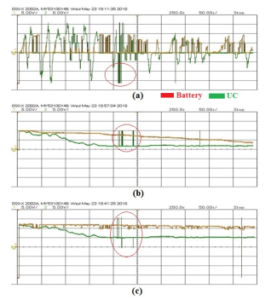
Figure 21: Case-I: Battery and UC (a) Current (b) SOC and (c) Voltage (VT) comparison in Real-time laboratory environment
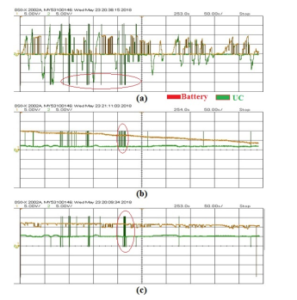
Figure 22: Case-II: Battery and UC (a) Current (b) SOC and (c) Voltage (VT) comparison in Real-time laboratory environment
As the system is run for 500 seconds, few noises are present in the results which are highlighted in the results plotted. For average power requirements battery is acting as the energy source and for peak power requirements ultracapacitor is the source. Vehicle performance and energy efficiency is improved as ultracapacitor has successfully absorbed the generated power during braking.
6.2 Case-II: Battery fully charged but UC less charged (Batt-SOC=100% & UC-SOC=25%)
Battery is full charged but ultracapacitor is charged at 25% SOC. It can be seen that during the cruising mode of operation battery is supplying the average power required but during accelerating mode the ultracapacitor is unavailable to meet the system peak power requirements once its SOC level reaches below 20% as shown in Figure 22. Ultracapacitor absorbs the regenerative braking power. Ultracapacitor is only able to meet the demands of the vehicle till its SOC reaches the bottom threshold of 20%. Once the SOC falls below its lower threshold, the vehicle may no longer be able to accelerate thereby hindering its performance hugely calling for an external/internal charging based on system architecture.
6.3 Case-III: UC fully charged but Battery less charged (Batt-SOC=25% & UC-SOC=100%)
Battery is charged at 25% whereas ultracapacitor is fully charged. Since battery is very low charged, it cannot meet the vehicles’ demands after its SOC falls below the threshold value of 20%. Ultracapacitor may continue to meet the vehicle average and peak demands till its SOC reaches 20% once the battery SOC is below 20% as shown in Figure 23. Ultracapacitor absorbs power while regenerative braking.
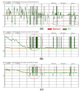
Figure 23: Case-III: Battery and UC (a) Current (b) SOC and (c) Voltage (VT) comparison in Real-time laboratory environment
The battery is active energy source till its SOC reaches the lower threshold value of 20%. Once both the energy sources are below its lower threshold value of SOC, the driver has to perform an external charging of battery accompanied by an external (Plug-In) or internal (through battery) charging of ultracapacitor ensure smooth operation of the vehicle.
7. Discussion and conclusion
Rickshaws, even-though being a common mode of transportation is subjected to very less research to improve its performance. Conventional E-rickshaws which employ a single energy source, has a lot of limitation in terms of driving range. In Indian scenario, E-rickshaws‘ success will be always measured by its driving range and cost. It is identified that combining a high power density device (UC) for sharing peak power demand with the traditional high energy density device (battery) will improvise the vehicle performance which was not earlier attempted in E-rickshaws. An improved SOC and terminal voltage characteristics can increase the driving range of the E-rickshaw. Also since the UC is able to meet the peak power demands, battery can be sized for a much lesser average current demand. This will considerably reduce the size and cost of the vehicle. Since the battery in a traditional e-rickshaw occupies almost 15-20% of its kerb weight, any minute reduction in weight and size of the battery will always result in better performance. Also UC possess faster charge/discharge characteristics than battery which can be utilized in absorbing regenerative power during deceleration and braking in a better way.
This paper have attempted for the hybridization of energy sources for an E-rickshaw system architecture in Indian scenario. The performance improvement was justified using simulation and implementation in real-time results in this paper. Successful implementation of a fuzzy logic based energy management algorithm has enhanced the performance of E-rickshaw. The vehicle dynamics was calculated real-time based on an Indian city drive cycle calculated using a GPS based PerformanceBox tool of VBOX motorsport. The vehicle was tested for three different driving modes of operation and three different battery and ultracapacitor state of charge conditions. It was found that the algorithm was working perfectly with less computation time and complexity. Implementation of a hybrid energy source for an E-rickshaw can extend its driving range. Also successful absorption of the generated regenerative power can further enhance the vehicle performance.
- J. Bremner, A. Frost, C. Haub, M. Mather, K. Ringheim, E. Zuehlke, et al., “World population highlights: Key findings from PRB’s 2010 world population data sheet,” Population Bulletin, 65(2), 1–12, 2010.
- S. K. Guttikunda, R. Goel, P. Pant, “Nature of air pollution, emission sources, and management in the Indian cities,” Atmospheric environment, 95, 501–510, 2014.
- BBC, “Indian cities dominate world air pollution list,” 2018.
- H. Mayer, “Air pollution in cities,” Atmospheric environment, 33(24-25), 4029– 4037, 1999.
- A. Mani, M. Pai, R. Aggarwal, “Sustainable urban transport in India: role of the auto-rickshaw sector,” 2012.
- J. Shah, N. Iyer, “Module 4c: two-and three-wheelers,” Sustainable transport: a sourcebook for policy-makers in developing cities. GTZ, Eschborn, 2004.
- J. Pucher, N. Korattyswaroopam, N. Ittyerah, “The crisis of public transport in India: overwhelming needs but limited resources,” Journal of public transporta- tion, 7(3), 5, 2004.
- M. S. Kumar, S. T. Revankar, “Development scheme and key technology of an electric vehicle: An overview,” Renewable and Sustainable Energy Reviews, 70, 1266–1285, 2017.
- V. Gulhane, M. Tarambale, Y. Nerkar, “A scope for the research and develop- ment activities on Electric Vehicle technology in Pune city,” in Electric and Hybrid Vehicles, 2006. ICEHV’06. IEEE Conference on, 1–8, IEEE, 2006.
- D. Majumdar, T. Jash, “Merits and Challenges of E-Rickshaw as An Alterna- tive form of Public Road Transport System: A Case Study in the State of West Bengal in India,” Energy Procedia, 79, 307–314, 2015.
- S. Tatipamula, “Study of a Parallel Electric Hybrid Three-Wheeled Motor Taxi,” IJCA Proceedings on International coriference on Green Computing and Techn% gy ICGCT, 1, 38–41, 2013.
- T. Hofman, S. Van Der Tas, W. Ooms, E. Van Meijl, B. Laugeman, “Develop- ment of a micro-hybrid system for a three-wheeled motor taxi,” World Electric Vehicle Journal, 3(3), 1, 2009.
- M. Mruzek, , I. Gajda´c, L. Kuˇcera, T. Gajdoˇsˇ´ık, “The possibilities of increasing the electric vehicle range,” Procedia engineering, 192, 621–625, 2017.
- S. Manzetti, F. Mariasiu, “Electric vehicle battery technologies: From present state to future systems,” Renewable and Sustainable Energy Reviews, 51, 1004–1012, 2015.
- A. Poullikkas, “Sustainable options for electric vehicle technologies,” Renew- able and Sustainable Energy Reviews, 41, 1277–1287, 2015.
- R. Kumar, “Evolution of solar rickshaw technology vis-a`-vis economic feasibil- ity,” in Advances in Electrical, Electronic and Systems Engineering (ICAEES), International Conference on, 646–651, IEEE, 2016.
- M. Sameeullah, S. Chandel, “Design and analysis of solar electric rickshaw: A green transport model,” in Energy Efficient Technologies for Sustainability (ICEETS), 2016 International Conference on, 206–211, IEEE, 2016.
- P. Mulhall, S. M. Lukic, S. G. Wirasingha, Y.-J. Lee, A. Emadi, “Solar-assisted electric auto rickshaw three-wheeler,” IEEE transactions on vehicular technol- ogy, 59(5), 2298–2307, 2010.
- M. A. Mallouh, L. McInnes, B. Surgenor, B. Peppley, “Intelligent Control for optimal performance of a fuel cell Hybrid Auto Rickshaw,” Energy Procedia, 29, 367–376, 2012.
- B. Masood, R. A. Naqvi, R. M. Asif, “Designing of a control scheme for the solar rickshaw in comparative study with conventional auto rickshaw,” in Engi- neering Technology and Technopreneuship (ICE2T), 2014 4th International Conference on, 324–329, IEEE, 2014.
- M. Hannan, M. Hoque, A. Mohamed, A. Ayob, “Review of energy storage systems for electric vehicle applications: Issues and challenges,” Renewable and Sustainable Energy Reviews, 69, 771–789, 2017.
- G. Ren, G. Ma, N. Cong, “Review of electrical energy storage system for vehic- ular applications,” Renewable and Sustainable Energy Reviews, 41, 225–236, 2015.
- A. K. Rohit, K. P. Devi, S. Rangnekar, “An overview of energy storage and its importance in Indian renewable energy sector: Part I–Technologies and Comparison,” Journal of Energy Storage, 13, 10–23, 2017.
- A. Singh, P. Karandikar, N. Kulkarni, “Feasibility of energy storage systems in different applications for sustainable energy,” in Emerging Technological Trends (ICETT), International Conference on, 1–6, IEEE, 2016.
- A. F. Burke, “Batteries and ultracapacitors for electric, hybrid, and fuel cell vehicles,” Proceedings of the IEEE, 95(4), 806–820, 2007.
- H. Fathabadi, “Fuel cell hybrid electric vehicle (FCHEV): Novel fuel cell/SC hybrid power generation system,” Energy Conversion and Management, 156, 192–201, 2018.
- S. Ahmadi, S. Bathaee, A. H. Hosseinpour, “Improving fuel economy and performance of a fuel-cell hybrid electric vehicle (fuel-cell, battery, and ultra- capacitor) using optimized energy management strategy,” Energy Conversion and Management, 160, 74–84, 2018.
- L. Kouchachvili, W. Ya¨ıci, E. Entchev, “Hybrid battery/supercapacitor en- ergy storage system for the electric vehicles,” Journal of Power Sources, 374, 237–248, 2018.
- N. Sulaiman, M. Hannan, A. Mohamed, E. Majlan, W. W. Daud, “A review on energy management system for fuel cell hybrid electric vehicle: Issues and challenges,” Renewable and Sustainable Energy Reviews, 52, 802–814, 2015.
- S. S. Kulkarni, N. Gandhi, N. Chaithanya, S. Govindarajan, “Ultra-Capacitor based Hybrid Energy Storage and Energy Management for Mild Hybrid Vehi- cles,” Technical report, SAE Technical Paper, 2014.
- W. Enang, C. Bannister, “Modelling and control of hybrid electric vehicles (A comprehensive review),” Renewable and Sustainable Energy Reviews, 74, 210–1239, 2017.
- S. Zhang, R. Xiong, F. Sun, “Model predictive control for power manage- ment in a plug-in hybrid electric vehicle with a hybrid energy storage system,” Applied Energy, 185, 1654–1662, 2017.
- D. Zhou, A. Al-Durra, F. Gao, A. Ravey, I. Matraji, M. G. Simo˜es, “Online energy management strategy of fuel cell hybrid electric vehicles based on data fusion approach,” Journal of Power Sources, 366, 278–291, 2017.
- M. Dawei, Z. Yu, Z. Meilan, N. Risha, “Intelligent fuzzy energy management research for a uniaxial parallel hybrid electric vehicle,” Computers & Electrical Engineering, 58, 447–464, 2017.
- J. Larminie, J. Lowry, Electric vehicle technology explained, John Wiley & Sons, 2012.