Design and Implementation a Novel System for Estimation Precise Transfer Function of DC Motor
 , Wan Zuha Wan Hasan 2, Nasri Sulaiman 3, Maryam bt. Mohd. Isa 3
Adv. Sci. Technol. Eng. Syst. J. 5(5), 1118–1125 (2020);
 DOI: 10.25046/aj0505136
A precise modelling plant system is substantial to improve the design of the DC motor controller, where a low accurate model may cause an unacceptable controller system. This study presents a hardware-in-the-loop (HIL) system for design a high speed motor data acquisition system (HSMDAQS) and injected collected data (ICD) Simulink model to estimate accurately the transfer function (TF) of a DC motor, without needing motor’s specification, providing high accuracy estimation tool that can be used to develop the design of a DC motor controller. The proposed system generates synching data to be imported into system identification (Sys Ident) application through a serial port. To show the performance design, a comparative study has been conducted between the experimental realization and simulation results in terms of dead time(td), rise time(tr), and settling time(ts), using a scope simulator. It was used three different DC motors to demonstrate the effectiveness of our approach in terms of average error step responses (AE-SR). The estimation results show that the best FIT between the response of the estimated TF and the collected data augmented by 95.03 % and stabilized despite using different motor’s speed. A comparison step response between experimental and simulation shows a very low deviation and minimized AE-SR below 10% for all tested motors. The developed system could be applied in a wide range of industrial applications, offering faster with accurately capturing data, high precision stabilized platform, a simpler implementation for dynamic systems, lower computational cost design, and flexibility.
1. Introduction
This paper is an extension of work originally presented in the Prime Asia 2019 conference [1]. DC motors are being used in robotic systems, home appliance and an electric vehicle and many other applications in case of simple structure, high performance, low-cost installation, and easy control speed. However, DC motor systems still have nonlinear parameters, variation in load dynamics, unpredictable inputs and disturbances, that affect their quality. Therefore, these motors should be controlled and analyzed to improve their performance [2-5].The concept of a real-time processing must be considered when an engineer designs develops and deploys a new automation and control system[6].The improvement of DC motors’ control arrangement to enhance their response characteristics is one way of reducing the amount of consumed energy and enhance the efficiency of the machines. Control systems engineering requires a knowledge of at least two basic components: (1)the plant model which describes the mathematically modeled behavior of the system;(2)the desired output [7]. For those systems are known their specifications, The DC motor can be mathematically modelled by using the dynamic equivalent circuit of DC motors based on the second order system as given in equation 1 [8, 9] .

where is the moment of inertia of the rotor, is motor viscous friction constant, is the speed of the shaft, is the electric inductance is the resistance of the coil, Kt is the motor torque and Ke is the back emf
By contrast, modelling TF not so straightforward in case of not all manufactured motors are provided their specifications, which was considered the first problem in the field of controller system [10] .One of the most interesting criteria to improve the controller schemes is the optimized TF model. Therefore , it is necessary to base the control system design on a process model [11]. Consequently, the structure of a TF model should be accurately realized that is without following a suitable estimation process , the classical approaches for compensator design and stability analysis are rendered ineffectual [12-17], especially for controller based PID and PI algorithm, that were extensively applied to enhance the speed performance in terms of step response characteristics td, tr, ts and overshoot [18, 19].However, the common problem in dynamic systems, that is impossible to describe the real plant system exactly in case of unbalancing behavior between controller and plant system. As some techniques are better than others for any given application, each method has its advantages and disadvantages [20].To estimate an approximate model for an unknown system’s specification, it is desired to load a certain input signal and to collect the output with thanks to Sys Ident, providing simplified models for complex systems from time-series data [21 , 22]. However, the errorless of parameter estimation depends on the preciseness of data information and sampling time.Therefore, the precision of acquiring data determined the accurate level of estimation models [23]. There are numerous studies focusing on estimation TF model of plant systems, several using costly data acquisition (DAQ)system based Sys Ident application for loading and collecting input /output data [24, 25], others using digital oscilloscope based Sys Ident [26, 27].By contrast, improve the accuracy of DAQ system could be considered the best solution to boost the precise estimation, and if the modeling of TF can be acquired precisely, the control system could be greatly improved performance [28].
The objective of this study is to obtain high accuracy mathematical model for DC motors without need their specifications, providing low cost design, besides investigating the simulation and experimental realization in terms of step response characteristics to show the efficiency of the proposed system. This paper proposed a novel HSMDAQS coupled with ICD Simulink model to improve the accuracy of collecting data to be used with Sys Ident application to formulate the mathematical models. The novel system has several advantages such faster and accurately capturing data, high precision stabilized platform, a simpler implementation for dynamic systems, flexibility and reducing the total parts cost design less than 20 US dollars. It is well known that the Sys Ident application is very limited, but the proposed methodology assists the novel system to minimize significantly the error capturing data (injected signal and θ) leads to increase the accuracy of TF form. The contributions of this study are: (1) Design a novel HSMDAQS to guarantee capturing data with very low error; (2) high precision stabilized system (3) improve the estimation of TF model for unknown system’s specification; (4) highly sensitives tool for measuring the deviation between experimental results and simulation. In order to verify the estimated TF models, a comparison between the simulation and the actual motor performed in terms of step response characteristics.
This article is organized as follows: Section 2 presents the proposed system design to estimate TF and provides a brief description of the hardware design and Simulink model. Section 3 presents the results of the estimation TF models, besides simulation and experimental results are carried, highlighting the step response characteristics, further discussing the comparison between them. Finally, the conclusion and recommendation are presented in section 4.
2. System design
This section presents the multi-steps of design methodologies to estimate accurately the mathematical model of a DC motor, giving a brief detail about the injected signals and the collected data in a time domain specification. The proposed method relies on four parts:(1) design HSMDAQS;(2) implement ICD Simulink model;(3) software and hardware setup;(4) using Sys Ident to estimate TF form. The proposed HSMDAQS has been employed to inject a different signal, and to acquire θ data, to be imported into Sys Ident application. It is chosen three diverse DC motors (M1, M2, M3) to investigate the effectiveness of the proposed HSMDAQS in terms of AE-SR. The speed motors M1,M2,M3 are 56,400,107 RPM respectively. The M1 and M3 are gearbox type with a reduction ratio equal to 1/10 for both, where M2 is a speed type. These motors are unknown dynamic parameters. Physically, to acquire data in data output, the tested motors were connected with HSMDAQS via a driver amplifier, where the collected output data imported from the dual hall encoder sensor (DHES) through collecting data port. By using a model-based design technique, it is designed ICD Simulink model to be implemented on HSMDAQS to inject step pulse and to collect data out. It is essential to calibrate the θ by measuring the RPM on a tachometer and scope simulator then adjusting the potentiometer of HSMDAQS to ensure that the recording data from the scope simulator is corresponding with the tachometer reading. This step is very important to minimize the divergence between experimental and simulation results. The communication between HSMDAQS and DHES is designed to inject signal to drive a motor and to acquire data out from DHES.
Figure 1 shows the proposed methodology to estimate precise TF model, it can be summarized into seven steps to meet the objective as follows:(1)connect HSMDAQS with PC through port6;(2)calibrate HSMDAQS by measuring θ in scope simulator and tachometer then proceed the adjustment between them to meet maximum similarity between experimental and simulation results;(3)using switching mode to inject one of the five different signals (square and triangle) wave by setting values as shown in Table 1;(4)acquiring data in data out and convert them into the time domain using iddata command to create a data object of (y, u, Ts);(5)import created data object into Sys Ident application to proceed the estimation process;(6) repeat again the same procedure with other injected signals until reached to signal 5;(7) from data model info, select the maximum percentage of best FIT that achieve high accurate TF model . The steps began with the measurement of data in data out of the tested motors M1, M2, M3 under different signals and voltages for a different speed with sampling time (Ts) equal to 0.02s to be imported into Sys Ident toolbox to evaluate a TF model of the tested motors. In this stage, the tested DC motor will begin to spin proportionally with the amplitude of the injected signal for the 30sec. The generated pulses are counted through the ICD model via Arduino analog inputs analog outputs. At this moment, the data in data out is ready to be imported accurately into the Sys Ident application.
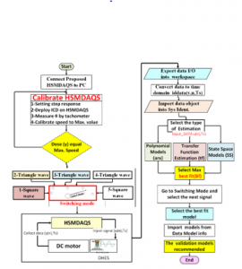
Figure 1: Methodology to estimate precise TF model
Table 1: Setting injected step signals
| shape | No | Amplitude (V) | Period
(s) |
Pulse Width(s) | Pulse Delay
(ms) |
| Square | Sig1 | 12 | 10/Ts | 5/Ts | 100 |
| Sig5 | 6 | 8/Ts | 4/Ts | 50 | |
| Vector Amplitude(V) | Vector Time(ms) | ||||
| Triangle | Sig2 | [0 ,6, 0 ,6 ,0] | [750 ,1500, 2250, 3000] | ||
| Sig3 | [0 ,2.4, 4.8 ,2.4 ,0] | [132.5 ,2653, 3975, 5.300] | |||
| Sig4 | [0 ,1.8, 3.6 ,1.8 ,0] | [0 ,1250, 2500, 3755,5000] | |||
2.1. Hardware design
As shown in Figure 2, the proposed HSMDAQS platform-constructed to be used as a high-speed capturing data. The platform constructed based on Arduino Uno with several electrical devices, HIL technique to communicate with the ICD Simulink model. It is used RF520 MOSFET to derive the tested motors, and designed a collecting data port to acquire data in data out, besides using a potentiometer to improve the accuracy of the collected data by calibrating the injected signal regarding maximum speed for each tested motors.

Figure 2: Proposed HSMDAQS
2.2. Proposed ICD simulink model
As shown in Figure 3, the ICD model is constructed based on Simulink block sets to run the HSMDAQS on external mode. It is designed several subsystem blocks such as a signal generator, count mode (CM), and selective switching mode (SSM). Figure 4 shows the SSM subsystem which contains five block set switches (SW) connected serially, to generate multiple signals. It is designed to choose one signal between five generated signals depending on setting the truth table, as illustrated in Table 2.

Figure 3: Proposed ICD simulink model

Figure 4: The SSM subsystem
Table 2: Suggested setting logic switching.
| Signal No. | Shape | Sw1 | Sw2 | Sw3 | Sw4 | Sw5 |
| Signal1 | Sequare | 1 | 1 | 1 | 1 | 1 |
| Signal2 | Triangle | 0 | 1 | 1 | 1 | 1 |
| Signal3 | Triangle | x | 0 | 1 | 1 | 1 |
| Signal4 | Triangle | x | x | x | 0 | 1 |
| Signal5 | Sequare | x | x | x | x | 0 |
Figure 5 shows the shape of generated signals (square and triangle) to inject into the tested DC motors. Based on selective switching mode, it can be chosen the shape of the signal depending on setting truth table, by setting sw1,2,3,4,5 on appropriate logic level to get the desired signal, for example, to generate triangle wave (signal 2), it should be setting sw1 on logic 0 and others switches on logic 1, and to generate square wave (signal 5), the sw4 should setting on logic 0 and sw5 on logic 1. Finally, to calibrate the generating voltage on 12V, it is suggested to inject the step response signal to drive the motor by setting sw5 on logic 0.
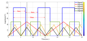
Figure 5: Five different injected signals into DC motors
The C.M subsystem designed to evaluate the motor’s speed based on count pulses, and to make a comparison between the present counts to the previous one from the last sample, and to specify whether a rollover has occurred between (-32768 to 32767), then to adjusts the cumulative number of counts and to remove the overflow counting. Examine the DHSE, it is observed some a certain error between the injected signals (u)and the angular speed signal (y), also when increasing the RPM speed, the capturing θ will become not smooth with augmented error as shown in Figure 6.
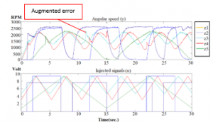
Figure 6: Five different injected signals and θ
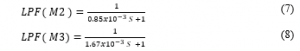
To reduce the effect of noise ,it is suggested to design a low pass filter (LPF) to be implemented on the ICD model, by measuring the cut off frequency( ) at maximum speed for tested motor as given in equation 3 , to find a filter constant ( ) as represented in equation 4.Based on scope simulator recording, the measuring cutting frequencies for the tested motors M1,M2,M3 are 73HZ,187HZ,95HZ respectively. To cut unwanted these frequencies, it should be evaluated the TF of the LPF motor as given in equation 5.
The resulted TF form of the LPF of each DHSE of the M1, M2, M3 are shown in equations 6, 7 ,8 respectively.

2.3. Software setup
By using a model-based design technique to construct the proposed ICD model and to do the communication with HSMDAQS, it is followed two steps. Firstly, by installing the ARDUINO I/O block set on MATLAB respiratory using the IDE ARDUINO program to scratch the application on the Arduino board. This program acts as a server for passing information between the hardware and the Simulink model. Together, these elements allow us to access Arduino digital inputs/outputs, analog inputs and read encoders through the Simulink model. Secondly, run MATLAB as an administrator to run the ICD model based on ARDUINO I/O block set that has been appeared in the respiratory library. Once the ARDUINO I/O Simulink block set installed, the Arduino IO block set (Digital Write block, the Encoder Read block, the Arduino IO Setup block, and the Real-Time Pacer block) are ready to be used for hardware communication. The sketch IDE program runs continuously and receives the commands from the ICD model via the serial port to executes the commands and returns a result. The final Arduino communication setting located on the workspace detecting that the port connection with the Arduino Uno board is connected through com6. For further information about Simulink block sets for communicating with an Arduino Uno board, programming code refers to [30].
Afterward, set the current MATLAB directory to the location of the file install_ arduino.m (in the Arduino IO/ folder), this will be allowed the update path to be saved continuously. Finally, importing ARDUINO I/O Simulink block set into the respiratory library by typing (install Arduino) at the MATLAB command line to run the IDE script through Simulink. The script simply adds the relevant Arduino IO folders to the MATLAB path and saves the path. After completing these steps, the proposed HSMDAQS is ready to communicate with the ICD model to inject a signal and to collect data out from DHES.
2.4. Hardware setup
Figure 7 shows the hardware setup for acquiring data to be used with the Sys Ident toolbox. In this process for the data acquisition, the tested motors connected with HSMDAQS via collecting data port. To run the hardware-based Simulink model, it should keep communication between PC and HSMDAQS through collecting data port, using serial data port com6. This process provides additional advantages, for instance, more synching data, measured real-time via scope simulator further rejecting noisy data by proceeding further modifications through running hardware.
The communication between HSMDAQS and DHES through the ICD model will be beginning by sending the injected signal via pin A0 (Analog write) to drive the motor, then acquiring data in data out from DHES via (Digital read pins) D2 and D3, which already connected with Phases A and B of a DHES. Hence, sending a voltage through pin A0 input signal (data-u) and the encoder block set receives a couple of data through Digital read pins to generate single output speed data(y).
To run the proposed HSMDAQS in real-time, it should be configured Arduino board on Simulink using configuration parameter setting, by selecting Tools > Run on Target Hardware > Run. Afterward, the ICD model activated to acquire data in data out in time domain specification, which will be run internally on the host computer.
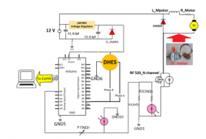
Figure 7: Hardware setup
2.5. Analysis based System Identification
This stage demonstrates how to estimate the TF model of M1, M2, M3 by acquiring data out θ based proposed HSMDAQS hardware to be imported into the Sys Ident toolbox. Mainly, this is done by modifying parameters within a given model until its output synchronizes as well as possible with the measured output. To check the validation of the proposed TF, it is taken a close look at the model’s output compared to the measured one on a data by finding the best FIT using the Model output box. By contrast, the accuracy of collecting data specifies the level of the best FIT estimation. Therefore, the HSMDAQS hardware should be designed to acquire synching data with lower noise.
Based on Sys Ident, it is used various estimated models, such as TF, state-space (SS), and polynomial (arx)models to choose a better estimation. It is essential to prepare the HSMDAQS for acquiring data. Firstly, connected M1, M2, M3 with the HSMDAQS system through data collecting port. Secondly, it is injected five various signals (triangle, square) waves to excite the system and to record the θ data. The reason behind using different injected signals is to provide sufficient data for model validation as PRBS signals, besides increasing the capability for finding a better accurate TF form. Figure 8 shows the several steps need to be followed to inject different signals and to collect the set of θ data from DHES using ICD Simulink model-based HSMDAQS as following:(1) run proposed HSMDAQS platform based proposed ICD Simulink model ;(2) using suggested SSM to inject five different signals with a frequency between 0.5 to 5 HZ;(3) the signal logging feature in Simulink will create a data set object in a workspace containing all the logged signals as time-series objects;(4) export five sets of data in data out (u, y) into the workspace, where (u) represents to an input signal and (y) to θ;(5) prepared the acquired data for estimation and validation, by converting the exported data into the time domain denoted data object using iddata command, to be imported into a workspace with Ts equal to 0.02s;(6) import created data objects (z1, z2, z3, z4, z5) into Sys Ident.
Figure 9 shows the estimation process to obtain a TF form. Firstly, it is selected the θ data object (z1, z2, z3, z4, z5) imported from the workspace/MATLAB into Sys Ident application, then using three different estimation types; Polynomial model(arx), State Space model (SS)and TF model. Afterward, specify the number of poles and zeros for different cases. Next, the estimation for each data object is figured as an impulse response time characteristic. Ultimately, it can be imported the TF model (TF1, TF2, TF3, TF4, TF5) and best FIT estimation for each impulse response by clicking the estimation box as shown in Figure 9.

Figure 8: Acquiring data based HSMDAQS

Figure 9:Importing data object into Sys Ident application
3. Results and Discussion
This section presents the estimation TF models based HSMDAQS, besides measuring the simulation and experimental step response parameters in terms of td, tr, ts, and SST, where the AE-SR is the performance indices used for the comparison of the results.
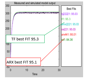
Figure 10: Model Output box for selection the estimation models
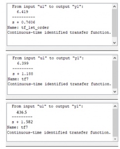
Figure 11: Estimated TFs form (a), for M1,(B)for M2,(c)for M3
3.1. Estimation TF model
It is used the Model Output box to show the best FIT of estimation. It is observed, when increasing the order of the estimation system, the best FIT will remain at the same value, therefore it is selected the first order system for the estimation because of the availability of a simple formula for designing a PID controller [31]. The estimated models are compared and selected regarding to the highest best FIT percentage. As shown in Figure 10, it is displayed that the best FIT of the estimated models are enhanced in TF form by 95.3 % and ARX by 95.01%, that means the novel HSMDAQS has rejected the noise significantly. The justification behind using three different types of DC motors is to verify the best FIT estimation in different conditions. It is observed that even though using different RPM speeds, the best FIT results are still the same value. That is mean the proposed HSMDAQS has excellent stability despite using different motor’s speed. Consequently, it is possible to use the proposal for any other types of DC motor even in industrial applications to estimate TF.
From Figure 11, it is important to highlight that the estimated TFs for M1, M2, M3, shown an absolute structure models due to low error capturing data.
3.2. Simulation results
In order to evaluate the proposed TFs models of each DC motor, there are several experiments are performed to obtain step response characteristics. Hence, the simulation scenarios are carried out with 3 estimated TFs models for the tested motors M1, M2, M3. The step response results were investigated by using a scope simulator as shown in Figure 12. It is observed that the tr and ts measured in the second unit for all tested motors.
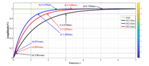
Figure 12: Simulation step response characteristics of M1,M2,M3

Figure 13: Actual step response of the tested motors,(a)M1 ,(b)M2,(c)M3
3.3. Experimental results
Figure 13 shows the plotted experimental results of the step response characteristics for M1, M2, M3. The experimental tests have shown that the step response characteristics are very convergence to simulation results.
To show the efficiency of the proposed HSMDAQS, the comparison between experimental and simulation results is performed. The deviation time (Δt) of the step response between experimental and simulation for each response parameter is represented in equation 9. The percentage error of the step response (PE-SR) and AE-SR can be calculated as represented in equations 10 ,11 respectively.

Table 3 highlights the comparison parameters between (simulation based models) and (experimental based HSMDAQS) in terms of td, tr, ts. It appears that the curves based on the proposed TF models are closer to the experimental results and the maximum AE-SR is less than 10%. Confidently, the HSMDAQS provides an acceptable △t [32, 33], shows the magnificent performance design to be utilized as the best solution for estimating high-quality TF form that can be utilized in a wide range of industrial applications.
Table 3: Simulation and experimental results comparison
| Parameters | M1 | M2 | M3 |
| △td(ms) | 2.49 | 2.93 | 1.88 |
| △tr(ms) | 155.64 | 97.25 | 298.03 |
| △ts(ms) | 359.9 | 542.32 | 372.89 |
| PE-SR (td) % | 2.74 | 4.18 | 1.36 |
| PE-SR (tr) % | 7.42 | 6.26 | 8.98 |
| PE-SR (ts) % | 9.83 | 17.97 | 6.8 |
| AE-SR % | 6.66 | 9.47 | 5.71 |
4. Conclusion
In this study, we have proposed a modern methodology and designed HSMDAQS to estimate the high accuracy TF model for unknown DC motor’s specifications. It was observed from the quantification of the results, despite there are three different tested DC motors was used in this approach, but the best FIT resolution of estimation stabilized and enhanced by 95.3 %, besides reducing AE-SR below 10%. Graphically, when experimental realization and simulation results are compared, basic similarities between them were observed. The developed system could be used to improve many design sectors, offering faster with accurately capturing data, high precision stabilized platform, simpler implementation for dynamic systems, lower computational cost design and flexibility.
Ultimately, it is recommended to use the proposed system to enhance the speed performance of a PI controller-based DC motor for the CNC machine. In the future, we will intend to implement the proposed HSMDAS on a Field Programmable Gate Array (FPGA), by taking in consideration variable reference speed, variable load and current limiting protection.
Conflict of Interest
The authors declare no conflict of interest.
Acknowledgment
The authors would like to thanks to UPM and MOE (MOE-FRGS scheme (03-01-17-1893FR).) for supporting and funding this research.
- F.S.M. ALKhafaji, W.Z.W. Hasan, M. Isa, N. Sulaiman, “A HSMDAQ System for Estimating Transfer Function of a DC motor,” Proceedings Prime Asia 2019 ,25–28, 2019.
- A. Jaya, E. Purwanto, M.B. Fauziah, F.D. Murdianto, G. Prabowo, M.R. Rusli, “Design of PID-fuzzy for speed Control of Brushless DC Motor in Dynamic Electric Vehicle to Improve Steady-State Performance,” Proceedings IES-ETA 2017 – International Electronics Symposium on Engineering Technology and Applications, 2017-Decem, 179–184, 2017, doi:10.1109/ELECSYM.2017.8240399.
- E. Gelik, H. Gor, “Enhanced Speed Control of a DC Servo System Using PI+DF controller tuned by stochastic fractal search technique,” Journal of the Franklin Institute, 1–28, 2019, doi:10.1016/j.jfranklin.2018.11.020.
- Y. Naung, A. Schagin, H.L. Oo, K.Z. Ye, Z.M. Khaing, “Implementation of Data Driven Control System of DC Motor by Using System Identification Process,” Proceedings of the 2018 IEEE Conference of Russian Young Researchers in Electrical and Electronic Engineering, ElConRus, 1801–1804, 2018, doi:10.1109/EIConRus.2018.8317455.
- W.G. Soliman, D. V. Rama Koti Reddy, D.A. Reddy, “Microprocessor-Based Performance Indices Analysis of Individual Systems Distributed Motion Control Strategies,” A Springer Nature Journal, 2(1), 1–11, 2020, doi:10.1007/s42452-019-1832-2.
- M. Torre, Halliburton, Designing real-time process controllers, Control Engineering, 2014.[Online].Available: https://www.controleng.com/articles/designing-real-time-process-controllers.
- A. Martinez, An Introduction to Control Systems: Designing a PID Controller Using MATLAB’s SISO Tool, ALL ABOUT CIRCUITS, 2015.[Online].Available: https://www.allaboutcircuits.com/technical-articles/an-introduction-to-control-systems-designing-a-pid-controller-using-matlabs.
- E.S. Addasi, “Modelling and Simulation of DC-Motor Electric Drive Control System with Variable Moment of Inertia,” ACEEE Int ernational Journal on Electrical and Power Engineering, Identification and Control, 4(1), 52–57, 2013, doi: 01.IJEPE.4.1.
- F.S.M. Alkhafaji, W.Z.W. Hasan, M.M. Isa, N. Sulaiman, “Proposed a Novel Method for Optimization DC Motor Controller,” Procceding of the 5th IEEE International Conference on Smart Instrumentation, Measurement and Applications (ICSIMA) , 2018.
- W. Wu, “DC Motor Identification Using Speed Step Responses,” Proceedings of the 2010 American Control Conference, 1937–1941, 2010, doi:10.1109/ACC.2010.5531349.
- S. Arun Jayakar, G.M. Tamilselvan, “Mathematical modelling and Robust PID controller Design for Compressed Air Pressure Control Process,” An International Journal of Applied Mathematics and Information Sciences, 13(4), 561–567, 2019, doi:10.18576/amis/130407.
- V.D. Yurkevich, N.A. Stepanov, “PWM Speed Control of DC Motor based on Singular Perturbation Technique,” International Congress on Ultra Modern Telecommunications and Control Systems and Workshops, 434–440 , 2014, doi:10.1109/ICUMT.2014.7002140.
- N. Tripathi, R. Singh, E. Engineering, N. Gwalior, M. Pradesh, “Analysis of Speed Control of DC Motor – A Review Study,” International Research Journal of Engineering and Technology (IRJET) e-ISSN:2395-0056, 02(08), 1616–1621, 2015.
- W. Wu, “DC Motor Parameter Identification Using Speed Step Responses,” Hindawi Publishing Corporation journal of Modelling and Simulation in Engineering, 2012 ,1–5, , doi:10.1155/2012/189757.
- D.X. Liu, “Design and Development of DC Motor Speed Control System based on ARM,” Advanced Materials Research, 926(930),1239–1242, 2014, doi:10.4028/www.scientific.net/amr.926-930.1239.
- T.A. Tutunji, “DC Motor Identification Using Impulse Response Data,” EUROCON 2005- The International Conference onComputer as a tool, 1734–1736, 2006, doi:10.1109/eurcon.2005.1630309.
- J.M. Esposito, M.G. Feemster, J.M. Watkins, “Role of a MATLAB Real-Time Hardware Interface within a Systems Modeling Course,” Proceedings of the 2004 American Society for Engineering Education Annual Conference and Exposition, 16(1), 41–50, 2006.
- T.L. Mien, V. Van An, B.T. Tam, “A Fuzzy-PID Controller Combined with PSO Algorithm for the Resistance Furnace,” Advances in Science, Technology and Engineering Systems Journal, 5(3), 568–575, 2020, doi:10.25046/aj050371.
- Y. Naung, S. Anatolii, Y. Htet Lin, “Speed Control of DC Motor by Using Neural Network Parameter Tuner for PI-controller,” Proceedings of the 2019 IEEE Conference of Russian Young Researchers in Electrical and Electronic Engineering, ElConRus2019, 2152–2156, 2019, doi:10.1109/EIConRus.2019.8656911.
- F.S.M. Alkhafaji, W.Z.W. Hasan, M.M. Isa, N. Sulaiman, “A Novel Method for Tuning PID Controller,” “Journal of Telecommunication, Electronic and Computer Engineering,” 10(1-12), 33–38, 2018.
- S. Khan, A. Paul, T. Sil, A. Basu, R. Tiwari, S. Mukherjee, U. Mondal, A. Sengupta, “Position Control of a DC Motor System for Tracking Periodic Reference Inputs in a Data Driven Paradigm,” 2016 International Conference on Intelligent Control, Power and Instrumentation, ICICPI 2016, 17–21, 2017, doi:10.1109/ICICPI.2016.7859665.
- S. Adewusi, “Modeling and Parameter Identification of a DC Motor Using Constraint Optimization Technique,” IOSR Journal of Mechanical and Civil Engineering (IOSR-JMCE) ,13(6), 46–56, 2016, doi:10.9790/1684-1306024656.
- B. Nayak, S. Sahu, “Parameter Estimation of DC Motor Through Whale Optimization Algorithm,” International Journal of Power Electronics and Drive Systems(IJPEDS), 10(1), 83–92, 2019, doi:10.11591/ijpeds.
- T.A. Tutunji, A. Saleem, “A Methodology for Identification and Control of Electro-Mechanical Actuators,” MethodsX 2, 219–231, 2015, doi:10.1016/j.mex.2015.04.001.
- D. Ramasubramanian, Identification and Control of DC Motors,MS.c Thesis, Escola Tècnica Superior d’Enginyeria Industrial de Barcelona, 2016.
- M. Fruk, G. Vujisić, T. Špoljarić, “Parameter Identification of Transfer Functions Using MATLAB,” Procceding International Convention on Information and Communication Technology, Electronics and Microelectronics (MIPRO) , 697–702, 2013, doi:10.1002/cpe.3949.
- M. Idrees et al., “Fuzzy Logic Based Calculation and Analysis of Health Index for Power Transformer Installed in Grid Stations,” in 2019 International Symposium on Recent Advances in Electrical Engineering (RAEE), 4, 1–6, 2019. doi: 10.1109/RAEE.2019.8887016.
- G.Y. Chen, J.W. Perng, “PI Speed Controller Design based on GA with Time Delay for BLDC Motor Using DSP,” Procceding of 2017 IEEE International Conference on Mechatronics and Automation, ICMA 2017, 1174–1179, 2017, doi:10.1109/ICMA.2017.8015983.
- C.Giampiero, Legacy MATLAB and Simulink Support for Arduino – File Exchange-MATLAB Central, 2016. [Online]. Available: https://www.mathworks.com/matlabcentral/fileexchange/32374-legacy-matlab-and-simulink-support-for-arduino
- D. Xue, Y.Q. Chen, D.P. Atheron,“PID controller Design,” in Linear Feedback Control: Analysis and Design with MATLAB,183–235, 2007.doi.org/10.1137/1.9780898718621
- W.L. Oberkampf, M.F. Barone, “Measures of Agreement Between Computation and Experiment: Validation Metrics,” Journal of Computational Physics, 217(2006), 5–36, 2006, doi:10.1016/j.jcp.2006.03.037.
- T. Magraner, Á. Montero, S. Quilis, J.F. Urchueguía, “Comparison Between Simulation and Experimental Results for The Energy Performance of Geocool Geothermal Experimental Plant,” Proceedings of the 11th International Conference on Thermal Energy Storage, (June), 2009.