Transient Analysis of a Line-Start Synchronous Reluctance Motor with Symmetrical Distributed Brass Rotor Bars

Adv. Sci. Technol. Eng. Syst. J. 5(5), 94–102 (2020);
 DOI: 10.25046/aj050513
In this paper, the performance evaluation of a line-start three-phase Synchronous Reluctance Motor (SynRM) with symmetrical distributed brass rotor bars is presented. The machine, which has been designed from a conventional three-phase induction motor (IM) NEMA frame stator is proposed as an alternative to a squirrel cage induction motor (SCIM). The 2D Finite Element Analysis (FEA) under ac magnetic transient solution was used to study some performance parameters of interest during starting transients. The experimental measurements were carried out in order to validate the numerical computation, to analyze the starting transients, and to explore the dynamic responses due to load variations. The FEA and experimental results of the synchronous reluctance motor with brass rotor bars (SynRM-BRBs) are compared to the results of a conventional three-phase SCIM of the same NEMA frame stator. The results evidenced that the reluctance torque developed by the SynRM-BRBs has a compounding effect on the accelerating torque, reaching its steady-state operational condition faster than the SCIM. The dynamic response of the SynRM-BRBs is faster in contrast to the SCIM during load variations. Furthermore, it was noted through measured results that the proposed line-start three-phase SynRM had a reduced dynamic no-load, and load current as opposed to the SCIM, thus positioning itself as a good candidate to replace the SCIM in applications that require a line-start ac motor with good starting transients and fast dynamic responses.
1. Introduction
In recent years, the increase in consciousness towards future sustainable growth, as required by international energy regulations, electric motor technologies for households, irrigation systems and industrial applications are endlessly under exploration for additional enhancements as far as the performance and prime costs are concerned [1]. Thus, the need to broaden ac machines’ technologies with good starting and dynamic abilities has surfaced [2]. The SCIMs are the most used singly fed line-start ac motors in households, irrigations systems and industrial applications. Despite their robustness and ease of usability, they suffer low efficiency, low power factor and longer time dynamic responses. The possibility to replace squirrel cage IMs with synchronous machines has emerged with several work focusing on the line-start permanent magnet synchronous motors (PMSynMs) that sought to bring solution to problems associated with the squirrel cage IMs low efficiency and low power factor. Therefore, the line-start PMSynMs are high-class alternatives to SCIMs, as they are well within the proposed IE4 efficiency levels, despite having excessive cost per kW [3]. Aside from the high cost of PM materials and high risk of demagnetization, the manufacturing process turns to be expensive, especially when permanent magnets with high hardness are necessitated [4], [5]. Consequently, line-start PMSynMs cannot easily substitute the very entrenched SCIMs [4].
During the last few decades, various scholars have extended their interests beyond the line-start PMSynMs by investigating the line-start SynRM that incorporates the constructional attributes of three-phase SCIM and SynRM. The line-start SynRM can develop an induction torque at starting and a reluctance torque during acceleration, and at synchronous speed. The rotor copper loss is zero during synchronous operation because there is no current induced in rotor bars. To solidify the possibility to replace the SCIMs with line-start SynRMs, several good work have sought to compare the performance between the three-phase SCIM and three-phase SynRM with cage bars on the rotor, for various applications [3-4, 6-7]. The Rotor design and dynamic equations that govern the performance of line-start SynRM with round copper bars are investigated in [8]. The dynamic model and transient analysis of line-start SynRM with copper bars in flux barriers are reported in [9] and [10]. Although the copper cage bars have lower rotor resistance and offer a finer synchronization ability than the aluminium, they contribute to the increase in rotor moment of inertia due to their high net weight.
However, modern line-start SynRMs possess a die-casted aluminium cage inside the rotor air barriers [4], [6], [7]. In principle, manufacturing costs of a squirrel cage IM are the same compared to SynRM with die-casted aluminium cage, but at full-load synchronous speed, the efficiency of the line-start SynRM with die-casted aluminium is higher, for the same frame size [7]. The weight of an aluminium conductor is less than the weight of a copper conductor, subjecting the rotor to less stress from centrifugal forces and reduced starting inertia, slighter vibration while running, and it is easily movable than an analogous copper rotor. Moreover, the low yield strength, low Young’s Modulus of elasticity and low melting point of the aluminium conductor serve as a good motivation to investigate other conducting materials to be used on the rotors of line-start SynRMs.
Therefore, this paper proposes a line-start SynRM with brass rotor bars. The line-start capabilities are acquired through round brass bars placed inside the air barriers on direct-axis and in the rotor core on the quadrature-axis as shown in Figure 1 (a). The characteristics of brass used in the proposed machine are well presented in [11]. Despite having a high electric resistivity compared to aluminium and copper, the brass presents a high yield strength, high Young’s Modulus of elasticity and high melting point. In the proposed motor, the brass bars are surrounded by cast epoxy resin. The latter permits to keep the bars steady and provide good electric insulation between the brass bars and the steel laminations. The bars are bolted, soldered and brazed to a brass end-ring at both end-points of stack lamination to form a cage.
The organization of this paper is in this manner: section 2 elaborates on ratings and specifications of the proposed SynRM-BRBs, and section 3 presents the model of the SynRM-BRBs. Section 4 deals with the ramifications of the number of rotor brass bars on synchronous parasitic torques during starting, while section 5 focuses on the performance evaluation of the proposed SynRM-BRBs by means of FEA. Section 6 provides details related to experimental validation, while section 7 summarizes the key findings of this paper and further elaborations regarding possible future work.
2. Motor Specifications and Ratings
In this paper, the starting transients and dynamic responses of the SynRM-BRBs is compared to a squirrel cage IM that has identical stator frame. Table 1 shows the ratings and specifications of the SynRM-BRBs and SCIM, while Figure1 depicts the rotor cross sections of both machines. The proposed SynRM has 24 symmetrical distributed brass rotor bars, thus only a pole is illustrated in Figure 1 (a). At the same time, the three-phase SCIM has 43 rotor copper bars as depicted in Figure 1 (b). From a design point of view, the number of stator slots and rotor brass bars should not equate [12]. The selection of the number of brass rotor bars depends on the number of air barriers per pole, and on the adequate combination between the number of stator slots and rotor bars for an un-skewed rotor.
Figure 2 depicts the brass bars and end rings for the SynRM, while Figures 3 (a) and (b) picture the prototype rotors for the SynRM with brass bars and squirrel cage induction motor respectively.
Table 1: Ratings and Specifications
| Description | Values |
| Stator slots | 36 |
| Poles pairs | 2 |
| Full-load line voltage, V | 380 |
| Base frequency, Hz | 50 |
| Full-load current, A | 12 |
| Full-load power, kW | 5.5 |
| Series conductors per phase | 144 |
| Stator external radius, mm | 105 |
| Stator inner radius, mm | 73.33 |
| Rotor inner radius, mm | 72.8 |
| Shaft radius, mm | 24 |
| Airgap Length, mm | 0.35 |
| Stack length , mm | 160 |
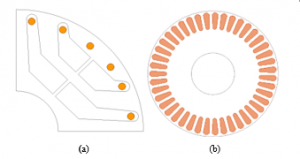
Figure 1: Rotors ‘cross section, (a) SynRM with brass bars, (b) squirrel cage induction motor

Figure 2: Photograph of brass bars and end rings
The adequate number of stator slots and rotor bars combinations for a 4-pole, 36-slot machine with a skewed rotor should be 36/25, 36/27, 36/28, 36/29, 36/30 and 36/43 [12]. In this paper, the combination of stator slots and rotor bars is 36/24 for the SynRM and 36/43 for SCIM. The rotor of the SCIM is skewed by a slot pitch. Alternatively, a non-skewed rotor design was opted for the SynRM-BRBs, thus making the combination of 36/24 to be adequate.

Figure 3: Photographs of prototype rotors (a) SynRM-BRBs (b) SCIM
3. Model of the SynRM with Brass Rotor Bars
The brass rotor winding is modelled as two identical windings, one on the direct-axis and the other on the quadrature-axis. Figure.4 illustrates the d-and q-axis equivalent circuital models of the SynRM-BRBs. The voltage equations that describe the electrical characteristic of the SynRM-BRBs, in rotating arbitrary reference frame are in (1)-(4).

where , the subscripts s and r indicate the variables associated with the stator and rotor respectively, while the superscript r refers to the rotating reference frame, λsd and λsq are the d-and q-axis stator flux-linkages, λrd and λrq are the d-and q-axis rotor flux-linkages, ω and ωr are the synchronous and rotor speeds, in electric radians respectively. The two values of rotor resistance for d-and q-axis in (3) and (4) contemplate the non-isotropic character of the SynRM rotor. The flux-linkages equations are given in (5)-(10).
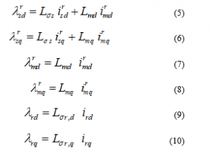
here Lσs and Lσs are the stator and rotor leakage inductances, Lmd and Lmq are direct-and quadrature-axis magnetizing inductances.
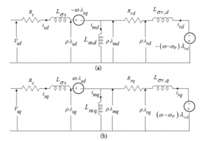
Figure 4: Equivalent circuit of the SynRM-BRBs, (a) direct-axis circuital model, (b) quadrature-axis circuital model
The torque developed by the three-phase SynRM with brass rotor bars is expressed in (11).
![]()
Ignoring the friction coefficient, the dynamic equation of the SynRM with cage bars that governs the torque balance at the shaft is generally expressed as

here p is the number of poles, J is the total rotor moment of inertia and TL is the load torque. The electromagnetic torque in (11) has two integrant expressions. The first expression is the reluctance torque, which is the torque at rated synchronous speed, and this torque pulsates at two times the slip frequency during holding phase of the motor [4]. The second expression is the asynchronous torque, which is the torque developed at standstill, also known as pullout torque. This torque exists only when the SynRM is out of synchronism. A detailed derivation of the asynchronous and reluctance torques is delineated in [7].
4. Space harmonics and Parasitic Torques
The field harmonic caused by the rotor bar current, stator slotting and stator winding phase-spread can be obtained using (13), (14) and (15) respectively [11-12].
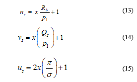
where x is any positive or negative number, Rb is the number of rotor bars, p1 is the number of fundamental pairs of poles, Qs is the total number of stator slots and σ is the phase-belt angle. The analysis pertaining to the existence of field harmonics owing to stator slotting, stator winding phase-belt and number of rotor bars in the SynRM-BRBs and SCIM is well documented in [11]. Furthermore, the field harmonic components emanated from the rotor gave rise to synchronous parasitic torques when linking with the field harmonics arisen from the stator with the same order [12-13]. From [11], it was noted that the synchronous parasitic torques occur in both the SynRM-BRBs and the squirrel cage IM. The effect of parasitic torques is more pronounced in the SynRM-BRBs than the squirrel cage IM [11]. To circumvent the synchronous parasitic torque caused by the interactivity between the stator field harmonics and rotor slot harmonics, (13) should not correlate (14) [11-12]. The effects of synchronous parasitic torques on starting transients of both machines are discussed in the succeeding section through FEA.
5. Finite Element Analysis
5.1. Machines’ flux density
The FEA has been carried out at nameplate voltage. The distributed three-phase double layer stator windings are supplied by three-phase sinusoidal voltage. The skin effect and core loss are not disregarded in the FEA. The skew of the SCIM rotor is accounted for in the FEA.
Figure 5 shows the flux density distribution plots; Figure 6 depicts the airgap flux density profiles, and their FFTs are given in Figure 7. It is clear from the FEA results in Figure 5 that there are localized saturations of stator back iron in both the conventional squirrel cage IM and SynRM with brass rotor bars. Localized saturations are also observed between some rotor teeth, and on some magnetic wedges of conventional squirrel cage IM. High flux density of about ± 1.2 tesla is noticed on the magnetic radial ribs of the SynRM-BRBs. In the latter, some magnetic tangential bridges of the upper air barriers exhibit a flux density of about ± 1.4 tesla, while the flux density in other magnetic tangential bridges levels between 1.2 tesla and 1.3 tesla.
The effects of stator slot openings are noticeable in the airgap flux density waveforms illustrated in Figure 6. The FFT results in Figure 7 (a) evidenced that the SynRM-BRBs has achieved a fundamental airgap flux density of 0.61 tesla. Elseways, the achieved fundamental airgap flux density of SCIM is 0.57 tesla. The 17th space harmonic are dominant in both machines. These harmonics are mainly due to stator slotting, and are reliant on the stator slots and pole pairs’ numbers. The 17th airgap space harmonics do not contribute to any asynchronous parasitic torque that may occur during starting because they do not produce rotor bar currents in both machines, whose magneto-motive force (MMF) harmonic has the same order. The 3rd airgap space harmonic is high in the SynRM-BRBs compared to the SCIM. The net airgap flux density is the result of the MMF harmonics and the airgap conductance harmonics. The latter is due to slot opening, leakage, skew, and saturation harmonics. The 3rd space harmonics are mainly caused by main flux path saturation in the stator back iron as noticed in Figure 5, and they are also due to airgap conductance harmonics caused by leakage slot magnetic saturation.

Figure 5: Flux density distribution, (a) Squirrel cage induction motor, (b) SynRM with brass bars
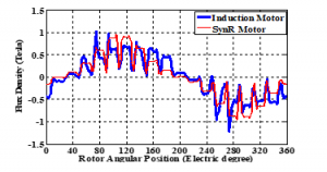
Figure 6: Airgap flux density profile
Although both conventional SCIM and SynRM with brass rotor bars show almost the same level of localized flux saturation in the stator back iron, the rotor of SynRM with brass bars shows a well-distributed main flux path saturation between air barriers, thus increasing the airgap 3rd flux density harmonic components. These airgap 3rd flux density harmonics have the advantage to positively contribute to the average airgap flux density and the machine torque density [14-16].
From figure 7 (b), it is clear that the 35th and 37th airgap flux density harmonics are dominant as far as high order number is concerned. They are mainly due to stator slot and phase-belt magneto-motive force harmonics. In the SynRM-BRBs the 35th and 37th airgap flux density harmonics produced in the brass bars currents with the 35th and 37th MMF harmonics, thus producing synchronous parasitic torques. On the other hand, the 21st and 23rd airgap flux density harmonics in the squirrel cage IM produced rotor currents with the 21st and 23rd MMF harmonics. The same can be stated for the 41st and 43rd airgap flux density harmonics. The latter produced rotor currents with 41st and 43rd MMF harmonics in the SCIM. The interaction of these space harmonics which are originated from different sources (stator and rotor), and having the same order number would contribute to the occurrence of asynchronous or synchronous parasitic torques [12-13].
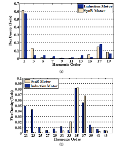
Figure 7: Airgap flux density harmonic components, (a) low order harmonics (b) high order harmonics
5.2. Motors’ performance parameters
The rated performance parameters in Table 2 were directly obtained from FEA at the nameplate values. The magnetizing reactance, which depends on the fundamental stator winding number of turns, winding factor, effective stack length, effective inverse airgap and saturation factor, is higher for the SynRM-BRBs compared to the SCIM. This justifies the SynRM with brass bars high value of the airgap fundamental flux density as observed in the previous subsection. The effective inverse airgap is proportional to the carter factor. It should be noted that the carter factor of the SynRM with brass bars does not account for rotor slot opening, which is not the case for the SCIM.
Table 2: Performance Parameters
| Description | Value | |
| IM | SynRM | |
| Stator resistance , Ω | 0.559 | 0.559 |
| Stator leakage reactance, Ω | 0.976 | 1.030 |
| Stator slot leakage reactance | 0.602 | 0.599 |
| Stator end leakage reactance | 0.212 | 0.212 |
| Stator differential leakage reactance, Ω | 0.162 | 0.217 |
| Magnetizing reactance, Ω | 31.21 | 41.95 |
| Rotor resistance, Ω | 1.002 | 2.377 |
| Rotor leakage reactance, Ω | 4.605 | 5.832 |
| Rotor end leakage reactance, Ω | 0.071 | 0.062 |
| Rotor slot leakage reactance, Ω | 4.069 | 6.659 |
| Rotor differential leakage reactance, Ω | 0.250 | 1.077 |
| Rotor skewing leakage reactance, Ω | 0.111 | 0 |
From Table 2, it is noticed that the value of the SynRM-BRBs rotor resistance is more than twice the rotor resistance of the SCIM. In addition to a high value of the brass resistivity compared to copper resistivity, the brass bars have a low section area compared to the squirrel cage bars. The skin effects, which are associated with the flux and current density distribution in brass bars or copper cage bars, influence both the rotor resistances and rotor slot leakage reactances. The skin effects are more significant in the SynRM with brass bars because 16 of the 24 brass rotor bars are surrounded by great amount of cast epoxy resin having small air bubbles. The skewing of the SCIM rotor has introduced the skewing magneto-motive force responsible for additional leakage component known as rotor skewing leakage reactance, thus slightly reducing the magnetizing reactance, while increasing the rotor leakage inductance. Though the SynRM with brass bars rotor differential leakage reactance is high, there is a huge difference as far as the stator differential leakage reactances are concerned. It should be noted that the stator differential leakage reactances are attenuated by the reaction of the rotor bars [12]. The two machines use the same stator NEMA frame and they have the same series conductors per phase, therefore given rise to almost the same values of stator resistance, slot leakage reactance and end connection leakage reactance.
5.3. Transient currents and mass rotor torques
Excluding the shaft, the inertia of the rotor is 0.08087 kg.m2 for the SynRM with brass bars and 0.122 kg.m2 for the squirrel cage IM. In the latter, the total weight of bars and end rings is found to be 6.418 kg, while it is found to be 3.279 kg for the SynRM-BRBs. The low rotor inertia in the SynRM with brass bars contributes to a fast response as far as the dynamic associated with the mass rotor torque is concerned, as evidenced in Figure 9. Furthermore, the transient currents shown in Figure 8 evidence that the SynRM with brass bars draws low starting currents compared to the SCIM.

Figure 8: Transient current, (a) Squirrel cage IM, (b) SynRM with brass bars
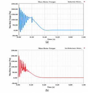
Figure 9: Transient mass rotor torque, (a) Squirrel cage IM, (b) SynRM with brass bars
5.4. Transient torques and Powers
The total winding energy losses during motor starting and acceleration depend on the stator current, rotor current, starting stator resistance and starting rotor resistance. The starting torque characteristics in Figure 10 indicate that the SynRM-BRBs has a shorter transient response time compared to the squirrel cage IM.
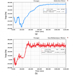
Figure 10: Starting torque, (a) Squirrel cage IM, (b) SynRM with brass bars

Figure 11. Transient input and output powers, (a) Squirrel cage IM, (b) SynRM with brass bars
The SynRM with brass bars acceleration begins as early as 6 mSec, crawls for about ± 8 mSec before accelerating up to synchronous operation. The interactivity of the 1st rotor slot field harmonic (11th order) and the 2nd stator winding phase-spread (11th order) field harmonic has given rise to synchronous parasitic torque which are partly responsible for the crawling effect in SynRM with brass bars as discussed earlier on. However, the squirrel cage IM has shown to have good acceleration without the crawling effect. Both motors have almost the same steady-state average torque, but the SynRM with brass bars exhibits high torque ripple contents compared to the squirrel cage IM. The interactivity of field harmonics of the electrical loading and the rotor anisotropy is responsible for the high ripple contents in the SynRM with brass bars. In addition to skewing the rotor, the optimization of rotor flux barriers microscopic design variables may assist with the mitigation of some torque harmonics that contribute to excessive torque ripple in the SynRM with brass rotor bars [17-23].
Operating at 80% of full-load, the input electric and output mechanical powers transient behaviors of the squirrel cage IM and the SynRM with brass bars are given in Figure 11 (a) and (b) respectively. The FEA results evidenced that the squirrel cage IM absorbs a high real power during starting as opposed to the SynRM-BRBs. This is because the squirrel cage IM locked rotor current is also high.
However, the steady-state squirrel cage IM absorbed real power is less as opposed to the power absorbed by the SynRM with brass bars. The mechanical out powers follow the torque pattern as observed in Figure 10. For the same torque density, the squirrel cage IM delivers more output power in comparison to the SynRM-BRBs. The low output mechanical power of the SynRM-BRBs is caused by high transient rotor winding losses and high critical slip. The latter is reached faster in the SynRM-BRBs, and it is mainly dependent on the rotor resistance and total rotor leakage reactance. Operating at 80 % of full-load, the efficiency of the SynRM-BRBs is found to be 73.3 %, while that of the squirrel cage IM is 79.58 % for the same operational condition.
6. Experimental Results
6.1. Motors’ starting transients
The SynRM with brass rotor bars analysed in this paper starts directly online with applied rated line voltage of 380 V. Neglecting the stator resistance, the maximum pullout torque that the motor is proficient to develop at a designated voltage V is [4]

where Ld = (Lσs + Lmd) , Lq = (Lσs + Lmq), θ is the load angle, Xd and Xq are the d-and q-axis synchronous reactances respectively. The d-and q-axis magnetizing inductances measured values are 34.3 mH and 10.77 mH respectively. Furthermore, the mesured value of stator leakage inductance is 4.2 mH. Figure 12 shows a photo of the experimental setup.

Figure 12: Experimental setup rig photo
Figures 13 (a) and (b) express the no-load starting transient torques of the squirrel cage IM and SynRM with brass bars respectively, while Figures 14 (a) and (b) depict the no-load starting transient currents. At starting, the SynRM developed an asynchronous torque owing to great value of induced current in the brass rotor bars.

Figure 13: Starting transient torque at no-load (a) squirrel cage IM (b) SynRM with brass bars
Furthermore, the starting currents on no-load of both motors are more than three times the rated currents. The squirrel cage IM motor starting current dropped fast once it begins to accelerate. The crawling effects during acceleration mode are significant in SynRM with brass bars as it was the case in the FEA results illustrated in the previous section. The crawling effects are caused by synchronous parasitic torques, and they may be mitigated by exploring new designs of the SynRM with brass rotor bars, with adequate combination between the number of brass rotor bars, flux-barriers per pole and that of stator slots for an un-skewed rotor [12-13].

Figure 14: Starting transient current at no-load (a) squirrel cage IM, (b) starting current of SynRM
6.2. Motors’ dynamic responses
This subsection deals with transients associated with the dynamic responses when the motor mechanical load is abruptly varied. The dynamic responses for currents of the SCIM and SynRM with brass rotor bars are shown in Figures 15 and 16 respectively. The results in Figure 15 denote that the no-load peak-to-peak current is low in the SynRM-BRBs compared to the squirrel cage IM. In the latter, there is a steady increase of currents for about 0.5 mSec and 1 mSec to peak-to-peak values of ± 9 A and ± 12 A, when the load is varied from no-load to 50% and 60% of the full-load respectively. There is a fast decrease of peak-to-peak current for about 0.35 mSec and 0.6 mSec, when the load is varied to no-load from 50% and 60% of the full-load respectively.
However, the results in Figure 16 indicate that the SynRM-BRBs exhibits a fast dynamic response compared to the squirrel cage IM, with a steady increase in currents for about 0.27 mSec and 0.35 mSec, to a peak-to-peak values of ± 8 A and ± 10 A, when the loads of 50% and 60% of the full-load are respectively applied. The decrease of peak-to-peak current lasts for about 0.1 mSec and 0.2 mSec when the loads of 50% and 60% of the full-load are respectively removed. Simply put, the SynRM-BRBs’ dynamic response is 0.23 mSec and 0.65 mSec faster than the squirrel cage IM when there is a load variation from no-load to 50% and 60% of the full-load respectively. Furthermore, the SynRM-BRBs’ dynamic response is 0.25 mSec and 0.4 mSec faster than the squirrel cage IM when the loads of 50% and 60% of full-load are respectively removed.

Figure 15: Dynamic responses, no-load to 50% of the full-load current (a) squirrel cage IM, (b) SynRM with brass bars

Figure 16: Dynamic responses, no-load to 60% of the full-load (a) squirrel cage IM, (b) SynRM with brass bars
7. Conclusion
This paper presented the analysis of a SynRM-BRBs as a strong candidate to replace the squirrel cage IM in applications that require a line-start ac motor with good starting transients and fast dynamic responses. The FEA results evidenced that the low rotor inertia of the SynRM-BRBs contributed to fast transient responses. Furthermore, the reluctance torque has been observed to have a compounding effect in both FEA and experimental results, on the accelerating torque of the proposed SynRM-BRBs.
The proposed line-start motor has proved to have fast dynamic responses, reduced steady state no-load, and load current compared to the squirrel cage IM. The main contribution of the proposed design is in the use of brass bars and end-rings on the rotor, having a high yield strength, high Young’s Modulus of elasticity and high melting point in contrast to copper and aluminium cages used in modern line-start SynRMs.
For future work, new designs of the SynRM with brass rotor bars, with adequate combination between the number of brass rotor bars, air barriers per pole and that of stator slots for a skewed and an un-skewed rotor may intensively be explored in order to alleviate the crawling effect due to synchronous parasitic torques. The optimization of rotor flux barriers microscopic design variables may also assist with the mitigation of some torque harmonics that contribute to high torque ripple contents in SynRM with brass rotor bars during synchronous operation.
- A.T. de Almeida, F.J.T.E. Ferreira and G. Baoming, Beyond Induction Motors Technology Trends to Move up Efficiency, IEEE Tran. Ind. Appl. 50 (3), 2103-2114, 2014, https://doi.org/10.1109/TIA.2013.2288425
- A. Castagnini, T. Känsäkangas, J. Kolehmainen, and P. Savio Termini, Analysis of the starting transient of a synchronous reluctance motor for direct-on-line applications, Coeur d’Alene, ID, USA, May 10-13, 2015, https://doi.org/10.1109/IEMDC.2015.7409047
- A.H. Isfahani and S. Vaez-Zadeh, Line start permanent magnet synchronous motors: Challenges and opportunities, Energy, 34(11), 1755-1763, 2009, https/doi.org/10.1016/j.energy.2009.04.022
- M. Gamba, E. Armando, G. Pellegrino, A. Vagati, B. Janjic and J. Schaab, Line-start synchronous reluctance motors: Design guidelines and testing via active inertia emulation, in IEEE Energy Conversion Congress and Exposition, Montreal, QC, Canada, Sept 20-24, 2015, ,https://doi.org/10.1109/ECCE.2015.7310340
- D. Mingardi and N. Bianchi, Line-start PM-assisted synchronous motor design, optimization, and tests, IEEE Tran. Ind. Elec, 64 (12), 9739-9747, 2017, https://doi.org/10.1109/TIE.2017.2711557
- A. Kersten, Y. Liu and D. Pehrman, Rotor Design of a Line-Start Synchronous Reluctance Machine with Respect to Induction Machine for Industrial Applications, in 13th IEEE International Conference on Electrical Machines, Alexandroupoli, Greece, Sept 3-6, 2018, https://doi.org/10.1109/ICELMACH.2018.8507053
- M. Gamba, G. Pellegrino, A. Vagati, and F. Villata, Design of a line-start synchronous reluctance motor,” in IEEE International Electric Machines Drives Conference, Chicago, IL, USA, May 12-15, 2013, https://doi.org/10.1109/IEMDC.2013.6556163
- A. Kersten, Y. Liu, D. Pehrman, and T. Thiringer, Rotor design of line-start synchronous reluctance machine with round bars, IEEE Tran. Ind. Appl, 55 (4), 3685-3696, 2019, https://doi.org/ 10.1109/TIA.2019.2914010
- V. Aguba, M. Muteba, D.V. Nicolae, Dynamic modelling and transient analysis of synchronous reluctance motor with cage bars in the rotor structure, in International Symposium on Power Electronics, Electrical Drives, Automation and Motion, Amalfi, Italy, June 20-22, 2018, https://doi.org/10.1109/SPEEDAM.2018.8445292
- V. Aguba., M. Muteba, D.V. Nicolae, Transient analysis of a start-up synchronous reluctance motor with symmetrical distributed rotor cage bars, in 2017 IEEE AFRICON, Cape Town, South Africa, Sept 28-20, 2017, https://doi.org/10.1109/AFRCON.2017.8095668
- M. Muteba, Comparison of dynamic behaviors between a synchronous reluctance motor with brass rotor bars and a squirrel cage induction motor, in IEEE PES/IAS PowerAfrica, Abuja, Nigeria, Aug 20-23, 2019, https://doi.org/10.1109/PowerAfrica.2019.8928746
- I. Boldea, S. A. Nasar, The induction machine handbook , CRC Press, New York, 2002.
- L. Wang, X. Bao, C. Di, Y. Zhou and Q. Lu, Analysis of synchronous parasitic torque in dual skew cage rotor induction motors with equivalent slot number, IET Elect. Power Appl., 2017, Vol. 11(8), 1357-1365, 2017, https://doi.org/10.1049/iet-epa.2016.0565
- K. Wang, Z. Q. Zhu, G. Ombach and W. Chlebosz, Average torque improvement of interior permanent magnet machine using Third Harmonic in Rotor Shape, IEEE Tran. Ind. Elec, 61 (9), 5047-5057, 2014, https://doi.org/10.1109/TIE.2013.2286085
- R. O. C. Lyra and T.A. Lipo, Torque Density Improvement in a Six-Phase Induction Motor With Third Harmonic Current Injection, IEEE Tran. Ind. Appl, 48 (5), 1351-1360, 2002, https://doi.org/10.1109/IAS.2001.955773
- H. A. Toliyat, S. P. Waikar, and T.A. Lipo, Analysis and Simulation of Five-Phase Synchronous Reluctance Machines Including Third Harmonic of Airgap MMF, IEEE Tran. Ind. Appl, 34 (2), 332-339, 1998, https://doi.org/10.1109/28.663476
- X. L. Bomela and J. Kamper, Effect of stator chording and rotor skewing on performance of reluctance synchronous machines. IEEE Tran. Ind. Appl., 38(1), 91-100, 2002, https://doi.org/10.1109/28.980362
- N. Bianchi, S. Bolognami, D. Bond, D and M. D. Pre, Rotor flux-barrier design for torque ripple reduction in Synchronous Reluctance and PM-assisted Synchronous Reluctance Motors. IEEE Trans. Ind. Appl, 45(3), pp. 921-928, 2009, https://doi.org/10.1109/TIA.2009.2018960
- V. Bilyi, D. Gerling and D. Bilyi, Flux barrier design method for torque ripple reduction in synchronous reluctance machines. in IEEE Transportation Electrification Conference and Expo, Asia- Pacific, Busan, Korea, June 1-4, 2016, https://doi.org/10.1109/ITEC-AP.2016.7512918
- M. N. F. Ibrahim, P. Sergeant and E. E. M. Rashad, Simple Design Approach for Low Torque Ripple and High Output Torque Synchronous Reluctance Motors, Energies, 9 (11), 1-14, 2016, https://doi.org/10.3390/en9110942
- N. Bianchi, M. Degano and E. Fornasiero, Sensitivity Analysis of Torque Ripple Reduction of Synchronous Reluctance and Interior PM Motors, IEEE Trans. Ind. Appl, 51(1), 2014, 187-195, https://doi.org/10.1109/TIA.2014.2327143
- N. Bianchi, S. Bolognani, D. Bon, and M. Dai Pre, ‘‘Torque harmonic compensation in a synchronous reluctance motor,’’ IEEE Trans. Energy. Con., 23(2), 466–473, 2008, https://doi.org/ 10.1109/TEC.2007.914357
- M. Muteba, B. Twala and D.V. Nicolae, Torque ripple minimization in synchronous reluctance motor using a sinusoidal rotor lamination shape, in the IEEE 22nd International Conference on Electrical Machines, Lausanne, Switzerland, Sept 4-7, 2016, https://doi.org/ 10.1109/ICELMACH.2016.7732588