A Cavity Structure based Flexible Piezoelectric for Low-Frequency Vibration Energy Harvesting
 , Siti Noraini Sulaiman 1, Abdullah 2, Muhammad Khusairi Osman 1
Adv. Sci. Technol. Eng. Syst. J. 5(5), 1042–1049 (2020);
 DOI: 10.25046/aj0505128
Piezoelectric energy harvesters (PEH) can be used in many areas of application, including human walking, railways, pavements and bridges. Piezoelectric energy harvesters are currently based on two types of external forces, namely pressure load and mechanical oscillation or vibration. A vibration energy harvesting (VEH) is a mechanical oscillation in a piezoelectric energy harvester that harvested electric energy. In the market, there is available energy harvesting device in good electric energy harvesting and very sensitivity. However, the price is too high and the fabrication process is too complex. Furthermore, one of the aimed of the research is to install the energy harvesting device at rotary compressor machine which has noise vibration frequency at 1 kHz to 10 kHz. This paper presented a cavity structure-based flexible piezoelectric vibration energy harvester (FPVEH) based on an IDE circuit for low-frequency vibration applications. A cavity structure (IDE circuity) combine with the flexible circuit (polyimide) and flexible membrane (polyvinylidene fluoride, PVDF) will increase the electric energy harvesting and sensitivity of the device. Therefore, the four designs (Design A to D) are used to investigate the effect of the electrode finger width and the gap between the electrode fingers (to investigate the cavity structure applying in the design). All designs have been characterized by FEA simulation using COMSOL Multiphysics 5.0 and experimental work using a sieve shaker vibration machine. A sieve shaker machine is worked as vibration frequency calibrator. However, the sieve machine can operate at 5 kHz and 7 kHz. Since these two vibration frequencies are in targeted vibration frequency. It is used as vibration frequency calibrator in this experimental work. The results from the FEA simulation and experimental work show the Design D has the highest electric energy harvesting compare to other designs. It has electric energy harvesting at 27.3 V for 1 minutes period. Design D has a wide electrode finger width and the wide gap between electrodes compare to other designs. The vibration frequency was also given the impact to energy harvesting whereby the vibration frequency at 5 kHz has the highest electric energy harvesting compare to vibration frequency at 7 kHz.
1. Introduction
Previously, the research [1] has been looked up into a vibration effect towards PMUT design and then, it has been energised and stored in a capacitor. This paper is an extension of work originally presented in 9th International Conference on Control System, Computing and Engineering (ICCSCE2019) [1]. The paper will look into the flexible membrane (PVDF) and cavity design (the gap between electrodes) in PMUT for energy improvement.
Recently, numerous studies have been investigated the use of piezoelectric energy harvesters (PEH) in various fields of application, such as human walking [2], railways [3], pavements [4–6], and bridges [7]. Several applications have emerged based on frequency and vibration studies [8]-[10], while others have been based on load or pressure acting on an energy harvesting device [4] and [11].
Flexible piezoelectric energy harvesting (FPEH) systems use elastomer pillars based on a piezoelectric polymer, whereby the stored energy has been converted into electrical energy in the clamped boundary on the piezoelectric layer [12]. Double-sided tribological layers, including polydimethylsiloxane (PDMS) and PDMS/multiwall carbon nanotubes with flexible polyvinylidene fluoride (PVDF), have been used as a triboelectric mechanism to enhance the performance of electric harvesters at various frequencies [13]. A flexible piezoelectric energy harvester with a sandwich structure using PIN-PMN-PT/epoxy has also been designed for wearable applications. The sandwich structure and the interdigitated electrode (IDE) film increase the flexural modulus of the membrane, resulting in a high electrical output [11]. The flexible piezoelectric energy harvester has been further developed using lead-free (Na0.5Bi0.5) TiO3-BaTiO3 piezoelectric nanofibers, which exhibit a high peak voltage output with a high load resistance [14]. Polymer piezoelectric materials, in collaboration with a beating mechanism, have been shown to generate a large force during low-frequency vibration and thus generate large output [15]. In one study, a piezoelectric PZT film was clamped to one end of a fixed wall and a load was mounted onto its other end [3]. This is called a cantilever piezoelectric beam model, and it has since been used in many vibration-type piezoelectric energy harvesters [3], [9], [16], [17].
Many researchers are examining the relationship between vibration and a resonance frequency that is capable of increasing the output power [8]. A vibration energy harvester with multiple nonlinear techniques can broaden the bandwidth of energy harvesting systems; however, there is a need to tune the resonance frequency [18], [19]. This design uses a parallel-plate structure consisting of a suspended spring-plate, which is a very complicated design and extra work is needed to tune the frequency [18]. A resonant vibration energy harvester was developed based on the cantilever model that can achieve a high strain and thus maximize the output power [20]. Another study on broadening the bandwidth in piezoelectric energy harvesters used a bi-stable composite laminate. This bi-stable piezoelectric energy harvester has a high geometrical nonlinear response that can broaden the frequency bandwidth during vibration [21]. Besides, a bimorph piezoelectric vibration energy harvester with flexible piezoelectric material was designed to improve the output power while lowering the resonance frequency. The bimorph-type piezoelectric increases the deflection, and this increases the strain inside the piezoelectric material and thereby improves the output power [9].
This paper presents a flexible piezoelectric vibration energy harvester (FPVEH) for use in low-frequency vibration energy harvesting applications. The energy harvesting device that available in the market can produce low energy harvester. There is an available energy harvesting device that can produce high electric energy harvester and sensitive to vibration frequency in the market. However, the price is a too high and complicated fabrication. The aimed of this research is to design and characterize a cavity structure-based flexible piezoelectric energy harvesting for low-frequency vibration applications. Beside of that, this design is to improve the quality of electric energy harvester and sensitive to vibration frequency. The target vibration frequencies are in the range 1 kHz to 10 kHz because the device will be installed at the rotary compressor that has noise vibration frequency from 1 kHz to 10 kHz. However, the available vibration frequency calibrator that is sieve shaker machine only can support 5 kHz and 7 kHz frequency. Since these two frequencies are in the range of target vibration frequencies, this sieve shaker has been used as vibration frequency calibrator in the experiment.
The four designs of FPVEH involving different in the gap between electrodes and different in the width of electrode fingers have been simulated and tested and demonstrated a significant performance in the result. All of these will be explained in the next section. The contribution of this research is a cavity design which is the gap between electrode fingers and a flexible circuit that has significant performance in electric energy harvesting. The investigation of different electrode fingers gap will be shown the significant of cavity design in FPVEH. The next section presents the design and methodology for the piezoelectric vibration energy harvester, while the finite element analysis (FEA) simulation method and experimental method are also described. The FEA simulation results and experimental results are discussed in the results and discussion section, and the last section presents the conclusion.
2. Design and Method
The PMUT design and method are presented in this section. A cavity-based flexible piezoelectric energy harvesting has been elaborated in terms of structure and mechanical properties that related to energy harvesting. Furthermore, a procedure and method are presented in this section.
2.1. IDE Circuits Structure
Four different IDE circuits have been designed to examine the effect of the different gap between electrodes of FPVEH and the electrode finger width of the FPVEH that harvested the electrical energy. Hereby, the electrode finger width and electrode finger gap were the two parameters that were investigated in low-frequency vibration. The design parameters are shown in Table 1. The schematic diagram of the IDE circuit is shown in Figure 1 and is referred to as Design A.
Table 1: IDE circuit design parameters
| Parameter | Design A(mm) | Design B(mm) | Design C(mm) | Design D(mm) |
| IDE width | 0.5 | 0.5 | 1.0 | 1.0 |
| IDE gap | 0.5 | 1.0 | 0.5 | 1.0 |
| IDE length | 20.5 | 26.0 | 25.0 | 29.0 |
As presented for Design A in Figure 1, the electrode finger gap between the positive and negative electrodes was 0.5 mm, the electrode finger width was 0.5 mm, and the IDE circuit length was 20.5 mm.
Polyvinylidene fluoride (PVDF) was attached to the top of the IDE circuit. The IDE circuit was made of polyimide (PI) as a dielectric and flexible membrane, and copper (Cu) was used for the finger electrode of the IDE circuit. The 3M tape was attached on top of PVDF and IDE circuit and then worked together as a new structure flexible membrane in harvesting electric potential difference of low-frequency vibration. The schematic diagram of the flexible piezoelectric vibration energy harvester (FPVEH) designed in this study is shown in Figure 2.
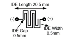
Figure 1: Schematic diagram of IDE circuit Design A.
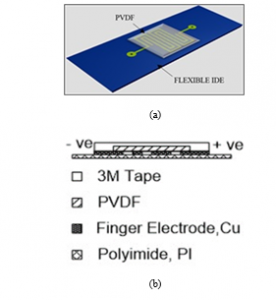
Figure 2: Schematic diagram of the flexible piezoelectric vibration energy harvester; (a) top view and (b) side view.
The thicknesses of the 3M tape, PVDF, Cu and PI are shown in Table 2. The contribution in this design of FPVEH is a cavity added between PVDF and PI and clamped by electrode fingers at both ends left and right. It gives more flexure to the membrane and oscillates smoothly if there an external force acting on both top and bottom membrane. The four IDE circuit designs were created using Proteus 8 software; these are illustrated in Figure 3. The fabricated IDE circuit is depicted in Figure 4, whereby the yellow material is a coverlay made from PI and the shiny circuit is made from Cu. The completed fabrication of the FPVEH is shown in Figure 5.
Table 2: The thickness of material in flexible piezoelectric vibration energy harvester design.
| Material name | Thickness (mm) |
| 3M tape | 0.88 |
| PVDF | 0.11 |
| Finger electrode, Cu | 0.035 |
| Polyimide, PI | 0.025 |
The readout circuitry for the energy harvester system is presented in Figure 6, and it is also called a full-bridge rectifier circuit, consisting of four diodes, a capacitor and a resistor. This full-bridge rectifier circuit converted the AC electric potential difference from the FPVEH into DC voltage and stored it in a capacitor. The value of the capacitor was 47 μF and it was used as a filter to reduce the ripple voltage while also acting temporary storage. The resistor had a value of 1 kΩ and was used as a load. A 1N4007 diode was considered suitable for use in low-power consumption because its peak-to-peak voltage was around 70 V.
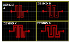
Figure 3: The four IDE circuit design in Proteus software.
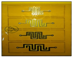
Figure 4: A fabricated IDE circuit.
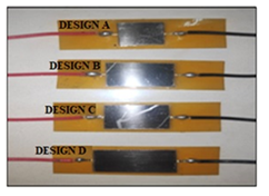
Figure 5: The completed fabrication of the FPVEH.
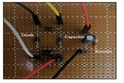
Figure 6: A full-bridge rectifier circuit.
2.2. Simulation Method
In the FEA simulation method, COMSOL Multiphysics 5.0 presented the direct piezoelectric effect on the piezoelectric material and elastic material. Firstly, defined the gravitational acceleration as amount 9.764 ms-2 in parameter definitions. A mass is represented of a pressure or a load per unit area with 0.5 MPa also has been defined in parameter definitions.
Then, set up the geometry in the geometry column. The flexible circuit consists of polyimide and copper, Cu is shown in Figure 7. Then, the geometric has been set up until the geometric structure shown in Figure 8. It consisted of 3M tape at the top layer followed by PVDF, copper and polyimide.
Then, set the material properties in the material properties column. The material properties of all materials are shown in table 3.
Table 3: Mechanical properties of all material
| Material name | Mechanical properties | ||
| Young’s modulus (GPa) | Poisson ratio (na) | Density (kg/m3) | |
| PVDF | 8.3 | 0.18 | 1780 |
| Copper, Cu | 128 | 0.36 | 8920 |
| Polyimide | 7.5 | 0.35 | 1420 |
| 3M Tape | 0.0045 | 0.499 | 980 |
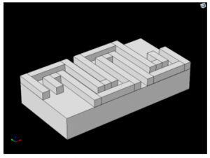
Figure 7:. Top view of set up flexible circuit in the geometric column in COMSOL Multiphysics
Next, select the suitable physics studies such as solid mechanics, electrostatics and Multiphysics. Selected the proper domain and put in physics studies column. For example, all materials are solid, then all domain belongs to solid mechanics. In solid mechanics, both ends at the left and right of the FPVEH are clamped. These clamped made the FPVEH oscillated freely when there was an external force acted on the surface of the membrane from the top or bottom. Then, select PVDF as an electrostatic domain. PVDF is a material that can convert mechanical property to electrical property and put the domain it into electrostatics study.
Then, select the suitable mesh, for instance, used size normal in the range 0.342 mm to 1.9 mm, used swept and the distribution, and select all domain put into distribution column. The mesh of geometry is shown in Figure 9.
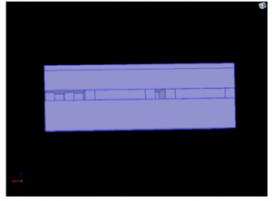
Figure 8: Side view of completed geometric setup in COMSOL Multiphysics
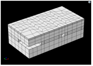
Figure 9: Mesh of geometry
Then, select the frequency domain as the study method. Furthermore, selected frequency range from 0 to 10 kHz with step 0.5 kHz as frequency input and put into the frequency domain. Lastly, in the result, the electric potential and electrical displacement were selected for plotted the graph. In electric potential result, the graph total voltage against frequency input has been plotted whereby in electrical displacement, the graph membrane displacement against frequency input has been plotted.
2.3. Experimental method
In this experimental, two parameters have been studied such as the effects of different electrode finger width of FPVEH and the effect of the different gap between electrodes of FPVEH during vibration. The electrical output voltage has been used as a benchmark of different studies to indicate the performance of the energy harvesting device. The four designs of FPVEH with different electrode finger and the different gap between electrodes have been tested using a sieve shaker to characterize their performances.
In experimental, a sieve shaker machine has been used to apply a vibration effect to the FPVEH. The FPVEH was placed on top of sieve shaker with both ends clamped using foam tape. Foam tape was worked as clamped at both ends as shown as a triangle in Figure 10 (a). The gravitational acceleration as amount 9.764 ms-2 has been set up to the sieve shaker machine with 0.5 MPa mass load. As one of the aimed of this research is to obtain electric harvesting energy from the rotary compressor within the range of frequency noise 1 to 10 kHz. In the laboratory, there is no calibrator machine can support 1 kHz to 10 kHz vibration. However, this sieve shaker machine can be operated at 5 kHz and 7 kHz only. Since the operation frequency, 5 kHz and 7 kHz are still in the range of rotary compressor frequency noise (1 kHz to 10 kHz), this sieve shaker machine has been used as a calibrator vibration machine.
The sieve shaker has a function to set time duration. The time duration can be used for investigating the energy stored in the period of time. The sieve shaker can support the period of 1 minute, 5 minutes, 10 minutes, 15 minutes and 20 minutes.
The output measurements comprised the electric field charge collected in the capacitor. Each of four designs (Design A to D) energy harvesting device was placed on top of the sieve shaker machine, and its electrodes were connected to the readout circuitry. The output of readout circuitry was measured by multimeter, and then it was observed and recorded the measurements. The experiment utilized the sieve shaker vibration machine to characterize the performance of four designs of different electrode finger width of FPVEH and different of the gap between electrodes of FPVEH that caused by vibration were shown in Figure 10.
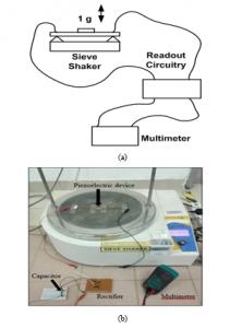
Figure 10: The experimental method to characterize the four designs with a different electrode finger width of FPVEH and the different gap between electrodes of FPVEH caused by vibration, (a) the schematic diagram, and (b) test field.
3. Results and Discussion
This section is divided into two parts that, respectively, present the simulation results and the experimental results. In the simulation results, two investigations were conducted to examine the effect of different IDE electrode finger widths and different IDE electrode gaps on the displacement of the membrane and the subsequently harvested an electric field accordingly to frequency input given. In the experimental result, the investigations were done on four designs with different electrode fingers width and different electrode gap (Design A to D) that have been affected on potential different, V by the energy harvesting device.
3.1. Simulation Results
FEA simulation is performed to characterize the total displacement of the membrane and the total electric potential difference harvested caused by the different of IDE electrode finger width and IDE electrode accordingly to the frequency input given. Figure 11 presents the simulation results for an IDE electrode finger width and gap of 1.0 mm and 1.0 mm, respectively for input frequency, 5000 Hz.
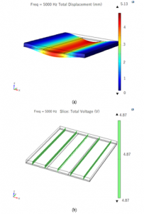
Figure 11: Simulation results for an IDE electrode finger width of 1.0 mm and an IDE electrode finger gap of 1.0 mm according to 5000 Hz; (a) displacement of the membrane (mm), (b) and total electric potential difference (V).
Figure 11(a) shows that the centre of the FPVEH membrane between the electrodes gap has been displaced by about 5.13 mm towards the negative z-axis at a frequency of 5000 Hz. The gap between the electrode fingers created a cavity between the PVDF and the polyimide. Therefore, the displacement of the flexure membrane increased when pressure was exerted on the surface of the FPVEH. Figure 11(b) shows that the FPVEH has a total electric potential difference of 4.87 volts for a frequency of 5000 Hz. Hence, Figure 11 was demonstrated the flexural membrane that has relation with total electric potential difference harvested by the FPVEH.
The simulation results for the four different electrode finger widths and gaps (Design A to D) are shown in Figure 12. The results show Design D with electrode finger width 1.0 mm and the gap between electrodes 1.0 mm has the highest electrical energy harvesting value compare to all design. Furthermore, Design D and Design C that has the same electrode finger width are the higher electric energy harvester compare to design B and Design A which are the smaller size of electrodes fingers width.
Next, Design D has higher electric energy harvesting compare to Design C whereby the Design D has a higher gap between electrodes compare to Design C. The Design A and Design B which are smaller in electrode fingers width and the gap between electrodes has lower electric energy harvesting. Subsequently, the vibration frequency has given the impact on harvested electric energy at low-frequency vibration applications whereby in the results shown the total voltage is highest at 5 kHz vibration frequency. It can show that the resonance frequency of Design D is at 5 kHz.
3.2. Experimental Results
In this section, the experiment results have been demonstrated. The investigation on the different electrode finger width of FPVEH and the different gap between electrodes of FPVEH were demonstrated. As explained in methodology, all four FPVEH designs (Design A to D) with different electrode finger and the different gap between electrodes were measured using a multimeter and sieve shaker as a vibrator calibrator. Table 4 is tabulated the experimental results of Design A, Design B, Design C and Design D for the different lengths of the periods.
The tabulated results are plotted in Figure 13. Figure 13 shows that the electric potential difference harvested by all four designs (Design A to D) increase relative to the increase in the length of time. Design D has an electrode finger width of 1.0 mm and a gap between the electrode fingers of 1.0 mm, and it has the highest electric potential difference value compared to the others. In addition to that, Design D and Design C with an electrode finger width of 1.0 mm have higher electric potential difference value compare to Design A and Design B that have lower an electrode finger width at 0.5 mm. Therefore, the wide electrode finger width has affected the electric potential difference value to increase.
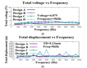
Figure 12: Simulation results for the four different electrode finger widths and gaps based on different frequency input; (a) total voltage (V) vs frequency (Hz), and (b) total displacement (mm) vs frequency (Hz).
Furthermore, Design D has higher electric potential difference value compare to Design C which indicates the gap between electrode fingers also affected an increase of electric potential difference value. Therefore, the increase of the electrode fingers gap has higher electric potential difference value.
Next, it can be seen that the electric potential difference harvesting in Figure 13(a) has a higher value compared to the value in Figure 13(b). The electric potential difference harvested in the experiment using the sieve shaker machine at 5 kHz was higher than at 7 kHz. Hence, the frequency vibration will affect electric energy harvesting by FPVEH.
In Figure 13 (a), Design D with an electrode finger width of 1.0 mm and electrode finger gap of 1.0 mm has the highest electric potential difference harvesting at 98.4 volts. The frequency of the sieve shaker machine is 5 kHz.
Table 4: Tabulated data for Design A, Design B, Design C, and Design C
| Period (min) | Total Voltage stored (V) | |||||||
| Design A | Design B | Design C | Design D | |||||
| Amplitude 5 kHz |
Amplitude 7 kHz |
Amplitude 5 kHz |
Amplitude 7 kHz |
Amplitude 5 kHz |
Amplitude 7 kHz |
Amplitude 5 kHz |
Amplitude 7 kHz |
|
| 1 | 12.6 | 10.4 | 17.1 | 15.5 | 20.1 | 18.9 | 27.3 | 23.0 |
| 5 | 36.8 | 35.0 | 44.8 | 42.2 | 46.0 | 44.0 | 52.2 | 50.8 |
| 10 | 51.3 | 50.3 | 56.2 | 54.1 | 61.2 | 60.7 | 64.1 | 63.4 |
| 15 | 65.9 | 64.5 | 73.0 | 71.3 | 75.7 | 75.0 | 82.0 | 81.5 |
| 20 | 72.9 | 72.0 | 86.2 | 84.7 | 89.0 | 88.9 | 98.4 | 96.4 |
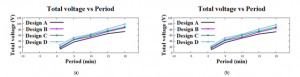
Figure 13: Total electric potential difference by experimental vibration results for the different designs and different lengths of time; (a) 5 kHz vibration and (b) 7 kHz vibration.
Table 5 shows the summary of the previous study that designed the vibration piezoelectric energy harvesting and their performances. The highest voltage has been harvested by [21] at 12 V with a resonance frequency of 19.1 Hz. The design can energise high voltage however, it needs to tune their frequencies until it reached the high electrical potential differences. The previous design was used PCB as substrate and it was hard to bend, thus the flexible circuit has been used to replace PCB as a substrate that can bend together with PVDF substrate. Therefore, more electrical energy has been produced. In this work has shown the significant performance in increasing the electric energy harvesting.
Table 5: Summary of previous study and their achievement.
| Author | Method | Achievement |
| [22] | Design PEH using clamped-clamped beam with proof mass. | Voltage: 4.5V at 1 g
Resonance Frequency: 42.8 Hz Displacement of plate: 1.56 mm Stress: 8Mpa |
| [23] | Design multi-layer piezoelectric energy harvester (MPEH). | Voltage: 3.79V at 1 g
Resonance frequency: 91 Hz |
| [24] | Design PEH based macro-fibre composite | Voltage: 2.8 V
in 2.12 s Resonance frequency: 8 Hz |
| [25] | Design metamaterial beam with double-layer resonators. | Voltage: 0.48 V
Resonance frequency: 348 Hz |
| [21] | Design PEH based cantilever tunable beam. | Voltage: 12 V at 0.7 g
Resonance frequency: 120 rad/s = 19.1 Hz |
| [1] | Previous work, design interdigitated electrodes on the PCB board with PVDF membrane and 1.0 mm finger width. | Voltage = 322 mV at 1 (9.764 m-2) g
and 1 minutes, Voltage = 0.005 V at 1 s. Frequency = 50 Hz |
| This work. | Design flexible piezoelectric based on PVDF and polyimide substrate. | Voltage = 27.3 V at 1 g (9.764 m-2) and 1 minutes,
Voltage = 0.455 V at 1s. Frequency = 5 kHz. |
4. Conclusion
This paper presented an investigation into the effect of electrode finger width as well as the gap between the electrode fingers and vibration frequency on the potential difference harvested by an FPVEH. The novel of FPVEH presented here was successfully designed and fabricated using IDEs, a flexible printed circuit, PVDF and 3M tape. The new structure flexible membrane and novel cavity design in FPVEH were successfully presented in this paper.
The full-bridge circuit was successfully developed to convert AC voltage into DC voltage, reduce the ripple voltage, and temporarily store energy in a capacitor. The electrode finger width, the gap between the electrode fingers and vibration frequency were also simulated using COMSOL Multiphysics to investigate the effects of these three parameters on the electric potential difference harvesting at the electrode and the displacement of the membrane. Furthermore, one experiment with different sets of frequency at a vibration machine was successfully conducted to characterize the FPVEH.
The experiment showed that the electrode finger gap had a greater effect on the electric potential difference harvesting by the FPVEH than the width between the electrode fingers. In this experiment with different setting frequencies at vibration machine was shown that the electric potential difference harvesting by all four designs using vibration machine at 5 kHz have higher than the electric potential difference harvesting by all four designs using vibration machine at 7 kHz. This indicates the vibration frequency has affected the electric potential difference has been harvested. Design D is the best design that harvesting the highest electric potential difference of 98.4 volts with a frequency input of 5 kHz. These concluded that the increases of electrode finger gap of FPVEH, and the wide of electrode finger width of FPVEH can increase the potential difference that harvesting by FPVEH. Moreover, the vibration frequency was also gave affected to energy harvesting when the results show that the vibration of 5 kHz has higher electric potential difference compare to vibration of 7 kHz that been harvested by FPVH.
Furthermore, a cavity that is a gap between electrodes has caused the increases of electrical energy harvesting by FPVEH. As a recommendation for future research, we propose the use of a power bank as a form of storage that can keep the electrical energy harvesting.
Conflict of Interest
The authors would like to declare that it is no conflict of interest in this paper publication.
Acknowledgement
The authors would like to acknowledge and express their highest appreciation to Research Management Unit (RMU), Universiti Teknologi MARA, Cawangan Pulau Pinang, Kampus Permatang Pauh for funding this fee of the paper. The authors also would like to express appreciation to Adavances Control System and Computing Research Group (ACSCRG), Universiti Teknologi MARA, Cawangan Pulau Pinang, Kampus Permatang Pauh for their contributions to this research.
- K.A. Ahmad, M.F. Abdullah, N. Abdullah, “Design and Characterization of an Interdigitated Electrode PVDF based Energy Harvesting Device,” in 2019 9th IEEE International Conference on Control System, Computing and Engineering (ICCSCE), 172–177, 2019, doi:10.1109/ICCSCE47578.2019.9068549.
- A.C. Turkmen, C. Celik, “Energy harvesting with the piezoelectric material integrated shoe,” Energy, 150, 556–564, 2018, doi:10.1016/j.energy.2017.12.159.
- M.Y. Gao, P. Wang, Y. Cao, R. Chen, C. Liu, A rail-borne piezoelectric transducer for energy harvesting of railway vibration, Journal of Vibroengineering, 18(7), 4647–4663, 2016, doi:10.21595/jve.2016.16938.
- C. Wang, S. Wang, Z. Gao, X. Wang, “Applicability evaluation of embedded piezoelectric energy harvester applied in pavement structures,” Applied Energy, 251, 113383, 2019, doi:10.1016/j.apenergy.2019.113383.
- X. Xu, D. Cao, H. Yang, M. He, “Application of piezoelectric transducer in energy harvesting in pavement,” International Journal of Pavement Research and Technology, 11(4), 388–395, 2018, doi:10.1016/j.ijprt.2017.09.011.
- X. Zhao, H. Xiang, Z. Shi, “Piezoelectric energy harvesting from vehicles induced bending deformation in pavements considering the arrangement of harvesters,” Applied Mathematical Modelling, 77, 327–340, 2020, doi:10.1016/j.apm.2019.07.048.
- G. Yesner, A. Jasim, H. Wang, B. Basily, A. Maher, A. Safari, “Energy harvesting and evaluation of a novel piezoelectric bridge transducer,” Sensors and Actuators A: Physical, 285, 348–354, 2019, doi:10.1016/j.sna.2018.11.013.
- L. Lamprecht, R. Ehrenpfordt, C.K. Lim, A. Zimmermann, “A 500 Hz-wide kinetic energy harvester: Outperforming macroscopic electrodynamic arrays with piezoelectric arrays,” Mechanical Systems and Signal Processing, 119, 222–243, 2019, doi:10.1016/j.ymssp.2018.09.025.
- T. Tsukamoto, Y. Umino, S. Shiomi, K. Yamada, T. Suzuki, “Bimorph piezoelectric vibration energy harvester with flexible 3D meshed-core structure for low frequency vibration,” Science and Technology of Advanced Materials, 19(1), 660–668, 2018, doi:10.1080/14686996.2018.1508985.
- X. Wang, H. Xiao, “Dimensionless Analysis and Optimization of Piezoelectric Vibration Energy Harvester,” International Review of Mechanical Engineering (IREME), 7(4), 607-624–624, 2013, doi:10.15866/ireme.v7i4.3812.
- Z. Zeng, L. Gai, A. Petitpas, Y. Li, H. Luo, D. Wang, X. Zhao, “A flexible, sandwich structure piezoelectric energy harvester using PIN-PMN-PT/epoxy 2-2 composite flake for wearable application,” Sensors and Actuators A: Physical, 265, 62–69, 2017, doi:10.1016/j.sna.2017.07.059.
- H.G. Çetin, B. Sümer, “A Flexible Piezoelectric Energy Harvesting System for Broadband and Low-frequency Vibrations,” Procedia Engineering, 120, 345–348, 2015, doi:10.1016/j.proeng.2015.08.631.
- Y. Zhu, B. Yang, J. Liu, X. Wang, X. Chen, C. Yang, “An Integrated Flexible Harvester Coupled Triboelectric and Piezoelectric Mechanisms Using PDMS/MWCNT and PVDF,” Journal of Microelectromechanical Systems, 24(3), 513–515, 2015, doi:10.1109/JMEMS.2015.2404037.
- B. Liu, B. Lu, X. Chen, X. Wu, S. Shi, L. Xu, Y. Liu, F. Wang, X. Zhao, W. Shi, “A high-performance flexible piezoelectric energy harvester based on lead-free (Na0.5Bi0.5)TiO3–BaTiO3 piezoelectric nanofibers,” Journal of Materials Chemistry A, 5(45), 23634–23640, 2017, doi:10.1039/C7TA07570G.
- H.-H. Huang, K.-S. Chen, “Design, analysis, and experimental studies of a novel PVDF-based piezoelectric energy harvester with beating mechanisms,” Sensors and Actuators A: Physical, 238, 317–328, 2016, doi:10.1016/j.sna.2015.11.036.
- Y. Kuang, M. Zhu, “Design study of a mechanically plucked piezoelectric energy harvester using validated finite element modelling,” Sensors and Actuators A: Physical, 263, 510–520, 2017, doi:10.1016/j.sna.2017.07.009.
- J. Fu, Y. Hou, M. Zheng, M. Zhu, “Flexible Piezoelectric Energy Harvester with Extremely High Power Generation Capability by Sandwich Structure Design Strategy,” ACS Applied Materials & Interfaces, 12(8), 9766–9774, 2020, doi:10.1021/acsami.9b21201.
- X. Wang, C. Chen, N. Wang, H. San, Y. Yu, E. Halvorsen, X. Chen, “A frequency and bandwidth tunable piezoelectric vibration energy harvester using multiple nonlinear techniques,” Applied Energy, 190, 368–375, 2017, doi:10.1016/j.apenergy.2016.12.168.
- M. Yuan, Z. Cao, J. Luo, J. Zhang, C. Chang, “An efficient low-frequency acoustic energy harvester,” Sensors and Actuators A: Physical, 264, 84–89, 2017, doi:10.1016/j.sna.2017.07.051.
- S. Du, Y. Jia, S.-T. Chen, C. Zhao, B. Sun, E. Arroyo, A.A. Seshia, “A new electrode design method in piezoelectric vibration energy harvesters to maximize output power,” Sensors and Actuators A: Physical, 263, 693–701, 2017, doi:10.1016/j.sna.2017.06.026.
- C. Lihua, X. Jiangtao, P. Shiqing, C. Liqi, “Study on cantilever piezoelectric energy harvester with tunable function,” Smart Materials and Structures, 29(7), 075001, 2020, doi:10.1088/1361-665X/ab859f.
- A. Damya, E. Abbaspour Sani, G. Rezazadeh, An innovative piezoelectric energy harvester using clamped–clamped beam with proof mass for WSN applications, Microsystem Technologies, 9, 2018, doi:10.1007/s00542-018-3890-6.
- Q. Lu, L. Liu, F. Scarpa, J. Leng, Y. Liu, “A novel composite multi-layer piezoelectric energy harvester,” Composite Structures, 201, 121–130, 2018, doi:10.1016/j.compstruct.2018.06.024.
- S. Balguvhar, S. Bhalla, “Evaluation of power extraction circuits on piezo-transducers operating under low-frequency vibration-induced strains in bridges,” Strain, 55(3), 2019, doi:10.1111/str.12303.
- J.-S. Chen, W.-J. Su, Y. Cheng, W.-C. Li, C.-Y. Lin, “A metamaterial structure capable of wave attenuation and concurrent energy harvesting,” Journal of Intelligent Material Systems and Structures, 30(20), 2973–2981, 2019, doi:10.1177/1045389X19880023.
No related articles were found.