Scattering of H-Wave by a Moving Dispersive Conducting Complex Object

Adv. Sci. Technol. Eng. Syst. J. 5(5), 955–959 (2020);
 DOI: 10.25046/aj0505116
The effect of the moving dispersive conducting complex scatterer on the scattering of incident H-wave is investigated herein. In this research, a simulation shows how the scattered phase and magnitude of a moving (rotating and translating) circular cylinder with higher conductivity, made of dispersive material, is affected in the case of incident H-wave (TE-mode) polarization. The Franklin transformation is applied to study the scattering of incident wave by a rotating dispersive higher conductivity cylinder, and then the effect of translating dispersive higher conductivity cylinder is investigated by applying the Lorentz transformation. This effect is studied at different speed of rotation. Also, this work shows that the pattern of scattered phase and magnitude are changed in terms of incident frequency. Moreover, a created model is used to demonstrate the impact of moving dispersive higher conductivity cylinder using backscattered static data which is generated using a comprehensive computational electromagnetics software(FEKO). The comparison between patterns of scattering of incident H-wave by a moving dispersive and non-dispersive higher conductivity cylinder is considered to show clear behavior of scattering patterns, in terms of the material of scatterer.
1. Introduction
The research is an expansion of the previous study published in 2019 IEEE International Conference on Wireless for Space and Extreme Environments (WiSEE) [1]. In previous work, the scattering of incident E-wave and H-wave by a rotating dispersive higher conductivity cylinder was investigated. The simulation result of this previous work shows a periodic pulse during rotation of dispersive conducting cylinder. It is found that the duration of these pulses is directly proportional to the speed of rotating dispersive higher conductivity cylinder, but inversely proportional to radius of dispersive higher conductivity cylinder. The difference between backscattered field of stationary case and backscattered field of rotating case is clear explicit in the incident H-wave polarization. For this reason, the incident H-wave is considered herein to study the effect of moving (rotating and translating) higher conductivity cylinder on the characteristic of the backscattered field. First of all, the Lorentz conversion is applied to figure out the effect of dispersive translating dispersive higher conductivity cylinder on the characteristics of the backscattered field. Secondly, Franklin conversion and Lorentz conversion are applied to study the characteristics of the backscattered phase and magnitude of moving dispersive conducting cylinder. Moreover, a created model is used to demonstrate the movement (rotation and translation) of dispersive higher conductivity cylinder using backscattered static data that is generated using FEKO. This data inserts into proposed model to demonstrate rotation and translation.
2. Scattered phase and magnitude
The effect of translation and rotation of a dispersive higher conductivity cylinder on scattered field (phase and magnitude) is investigated. The mathematical expression of scattered phase and magnitude is found by applying Lorentz and Franklin conversion [2]. Figure 1 shows the block diagram of the research problem.
It is assumed that a rotating dispersive higher conductivity cylinder is translated in the x-direction. Also, the incident wave propagates in the x-direction. Since, the magnetic field is in z-direction, so the electric filed is in y-direction by applying Maxwell’s equations. Also, the direction of rotation is in the direction.
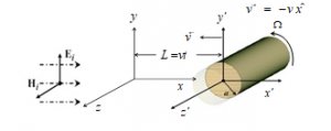
Figure 1: H-wave of moving dispersive conducting cylinder inrotatranslation
2.1. The effect of translating dispersive conducting cylinder
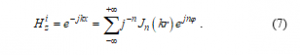
In this part, Lorentz conversion is applied to discuss the scattering of incident H-wave by a translating dispersive higher conductivity cylinder. The incident H-wave is defined as [3]

where .These fields, which are defined by and , are in laboratory frame. The Lorentz conversion is applied to compute fields in the co-moving frame using [4]
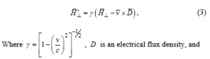
Where , is an electrical flux density, and is a speed of translation.
The expression of scattered magnetic field in co-moving frame can write as [5]
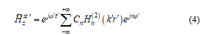
where is the unknown scattered coefficient. The unknown amplitude coefficient can be found by applying the boundary condition as [5].
The expression of magnetic field in the laboratory frame is computed using [6]
![]()
The backscattered magnetic field is given by
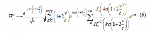
Equation defined the backscattered magnetic field by translating very good dispersive conducting circular cylinder. It is seen that when (stationary case), leads to (11-115) that generated by Balanis [7], in the case of scattering of incident H-wave by a stationary perfect conducting cylinder.
2.2. Effect of movement
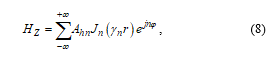
The scattering of incident H-wave by a rotating dispersive higher conductivity cylinder is investigated by taking the Franklin conversion. The expression of the magnetic field is written as [3]
Fields inside the dispersive conducting cylinder is computed using Maxwell’s equations as following [9],
where is the unknown transmission coefficient. The expression of scattered magnetic field can define as [9]
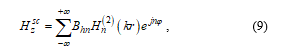
where is the unknown scattering constant. This unknown scattering coefficient is found using the boundary conditions on the surface of the dispersive conducting cylinder [10] and [11]. These coefficients are defined by
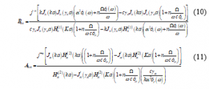
where . The scattering of incident H-wave by a rotating dispersive higher conductivity cylinder is computed using . An approximation to Lorentz transformation and is substituted into to find the mathematical model of the effect of movement of dispersive higher conductivity cylinder on the backscattered field. The formula of a backscattered field is given by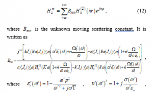
, where , , , , is the electron charge, called mass of charge, called damping coefficient, and is vacuum electric permittivity [1]. The backscattered field (far field), can be defined as
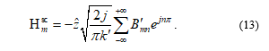
The new proposed model is shown in Figure 2. The characteristic of this model is computed as , so

where is scattered magnetic field of stationary perfect conducting cylinder [7].

Figure 2: Proposed model
3. Numerical result
Equation defines the far field ( backscattered phase and magnitude) of moving dispersive higher conductivity cylinder. It is considered that the dispersive higher conductivity cylinder has a radius equal to and the incident frequency changes from 2GHz to 20GHz. In this simulation, the conductivity of cylinder’s martial is (Copper). This simulation is taken place using a specific values of and .
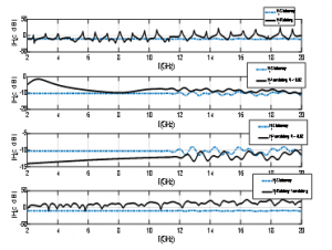
Figure 3: Magnitude of backscattered H-wave
It is shown the backscattered field (phase and magnitude) of the rotating, translating and moving dispersive higher conductivity cylinder cases in comparison with stationary case are shown in Figure 3. The graphs’ y-axis and the x-axis represent the magnitude the operating frequency of backscattered magnetic field respectively. The first graph is a comparison of the backscattered magnitude of a stationary and a rotating dispersive higher conductivity cylinder. The blue line represents the stationary case, and the rotating case is represented by black line. Visibly it is observed that the black line (rotating case) shows pulses as frequencies increases and the blue line (stationary case) shows tiny ripples in higher frequencies, as shown in the first graph.
The second and the third graph show the comparison of the backscattered magnitude of a stationary and translating very good dispersive conducting cylinder, that is heading in a positive direction (away from the source) and the negative direction (towards the source). When the dispersive higher conductivity cylinder is heading in a positive direction, the backscattered magnitude is shifted in the higher frequencies in comparison with the stationary case. On the contrary, the backscattered magnitude is shifted in the lower frequencies when the dispersive higher conductivity cylinder is heading in the negative direction. The effect of a moving dispersive higher conductivity cylinder on the backscattered magnitude is shown in the fourth graph. The backscattered magnitude shows a pulses and negative slop in the moving case.
Figure 4 shows the backscattered phase of rotating, translating and moving cases. The first graph shows the difference between the backscattered phases of stationary and rotating. This difference shows up as a periodic pulse. In the translating case, the difference between the backscattered phase of stationary and translating cases is shown in the second and third graphs. When the dispersive higher conductivity cylinder is heading in a positive direction, the phase difference appears as a series of pulses. The widths of these pulses increase as the dispersive higher conductivity cylinder heads in a positive direction. Also, slope of the pulses in the case of a positive translation is negative. On the contrary, the width of the pulses decreases when the dispersive higher conductivity cylinder heads in the negative direction. In this case, the slope of the pulses is positive. In comparison to the past work, the backscattered phase and amplitude of the moving non-dispersive conducting cylinder with high conductivity showed up a sinusoidal behavior, especially in higher frequencies [12]. The effect of movement of dispersive higher conductivity cylinder is shown in graph four.

Figure 4: Phase of backscattered H-wave
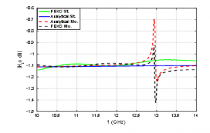
Figure 5: Magnitude of backscattered H-wave
The dispersive higher conductivity cylinder that is displayed in Figure 1 constructed by using a comprehensive computational electromagnetics software (FEKO). To construct the geometry of problem (Figure 1), It is assumed the radius, the height and the conductivity of cylinder are , and respectively. Also, the range of simulation frequency is from 10 GHz to 14GHz.
In this part, the generated stationary static data is inserted into proposed model that is sown in Figure 2. Figure 5 and Figure 6 show that the analytical and simulation results of the backscattered phase and magnitude show a similar behavior in the stationary (St) and moving (Mo) cases.
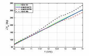
Figure 6: Phase of backscattered H-wave
4. Conclusion
In this research, the backscattered phase and magnitude of movement dispersive conducting cylinder is studied in the case of incident TE mode. The effect of the movement of the dispersive higher conductivity cylinder on the scattering of incident H-wave is studied. In this research, a mathematical model that represents the moving backscattered field (magnitude and phase) is created using Franklin and Lorentz conversion. It is found that the effect of the rotation shows as a periodic pulse on the patterns of backscattered phase and magnitude. Also, simulation result shows that the duration of pulses is affected when a speed and radius of dispersive higher conductivity cylinder are changed. In the translating case, the backscattered magnitude of an incident H-wave is shifted in the direction of higher frequencies when the dispersive higher conductivity cylinder moves away from the source of incident wave. Conversely, the backscattered magnitude of the incident H-wave is shifted in the lower frequencies when dispersive higher conductivity cylinder moves towards the source of incident wave. The phase difference of a backscattered field appears as series pulses in the translating mode. The slop of pulses is negative and the width of pulses increases when the dispersive higher conductivity cylinder moves away from the source of incident wave. When the dispersive higher conductivity cylinder moves towards the source of incident wave, the slop of pulses is positive and the width of pulses decreases. The demonstration results of the proposed model and an analytical results gives a similar backscattered phase and magnitude patterns. In comparison to the past work, the pattern of backscattered phase and amplitude of dispersive higher conductivity cylinder showed a periodic pulse. However, the pattern of backscattered phase and amplitude of non-dispersive higher conductivity cylinder showed a sinusoidal behavior, especially in higher frequencies. These phenomena display the impact of the electrical properties of material of scatterer on the scattering pattern of an incident H-wave.
Acknowledgment
The research is supported by the Center for Connected Multimodal Mobility (C2M2). Authors would also like to acknowledge U.S. Department of Homeland Security (DHS) Summer Research Team Program Follow-On, FY19 US Department of Education MSEIP Grant Award P120A190061, and National Science Foundation (NSF, No. 1719501, 1436222, and 1400991) grants. Any ideas, results, epilogue or commendation that are expressed in this study are for those author(s), and do not necessarily reverberate the opinions of (C2M2), USDOT, DHS, U.S. Department of Education, or NSF. The U.S. Government suppose no liability for contents or utilize therefrom.
- E. Abuhdima, Gurcan Comert, Ahmed Elqaouaq, Ashleigh Reeves and Williams Kellen, “Scattering of EM waves from a Rotating Dispersive Very Good Conducting Cylinder,” in 2019 IEEE International conference on wireless for space and extreme environments, October, 2019.
- Philip Franklin, “The meaning of rotation in the special theory of relativity,” Proc. Nat. Acad. Sci., 8(9), 1922.
- Harrington, Time Harmonic Elecromagnetic Fields, McGraw-Hill, 234, 1961.
- E. Abuhdima and R. Penno, “A New Model for Simulation of Scattered EM Fields from a conducting Cylinder in Rotation and Translation using Static Data,” in IEEE NAECON-OIS, 2017.
- Abuhdima, Esmail, “Simulation of the Scattered EM Field of a Moving Dynamic Object Using Static Data,” Ph. D Thesis, University of Dayton, 2017.
- H. Gholizade, “Radar Cross Section of Moving Objects,” The European physical journal, 2013.
- C. A. Balanis, Advanced Engineering Electromagnetics, John Wiley &Sons, Inc, 1989.
- E. Abuhdima and R. Penno, “Simulation of the scattered EM fields from a rotating conducting cylinder,” in IEEE International Radar, 2015.
- P. Hillion, “Scattering by a rotating circular conducting cylinder I,” Mathematical physics, 41, 1998.
- P. Hillion, “Scattering by a rotating circular conducting cylinder II,” Mathematical physics, 41, 1998.
- D. De Zutter, “Scattering by a rotating circular cylinder with finite conductivity, ” IEEE Transactions on Antenna and Propagation , AP-31(1), 166-169, 1983.
- E. Abuhdima and R. Penno,“The Effect of Rotation and Translation upon the Scattered EM Fields of a Conducting Cylinder,” in NAECON-OIS, 2016.
No related articles were found.