Fine Tuning the Performance of Parallel Codes

Adv. Sci. Technol. Eng. Syst. J. 5(4), 824–840 (2020);
 DOI: 10.25046/aj050497
We propose a multilevel method to speed highly optimized parallel codes whose runtime increases faster than their workload. This method requires the ability to solve large in- stances by decomposing them into smaller instances. Using a simple parallel computing model, we derive a mathematical model that predicts whether or not our method can im- prove performance and also predicts the amount of improvement attainable. Our method is tested and shown to be effective on three highly optimized BLAS (Basic Linear Alge- bra Subprograms) routines from Intel’s Math Kernel Library (MKL). Those routines are cblas dgemm, cblas dtrmm and cblas dsymm. On the Intel Knights Landing (KNL) platform our method speeds cblas dgemm by 33%, cblas dtrmm by 50% and cblas dsymm by 49% on double-precision matrices of size 16K x 16K, when the KNL’s default memory-clustering configuration (cache-quadrant) is used.
1. Introduction
The operation of moving of oversized and overweight packages onboard is called load-out. The oversized and overweight packages such as: 1) topside, jackets for oil and gas industry; 2) Big equipments for power stations; 3) Super-weighted equipments for oil refineries and thermal power plants.
The load-out task is based on several techniques such as skidding, lifting, float-on, etc and is a high-risk task. In this paper, a self-propelled trailers system is utilized to do load-out task. Adverse events can occur such as trailer overloaded, broken trailer structure, damaged path due to temporary breakdown such as tire explosion, the frequent failure of the Electronic Load Sensing (ELS). Engineers should give priority to solving the problem of damage to the road surface during transportation by many options in many different places [1, 2]. Theoretically, the self-propelled trailer system is navigated by methods such as GPS-based, IMU-based [3], vision-based [4], and combined method of the single mentioned methods [5].
However, this method has many limitations as follows:
- It is difficult to control the synchronous speed of tractors.
- It is difficult to adjust the center to lower the required position because each delegation is a different rotation center.
- It is unable to transport too heavy cargos.
The self-propelled trailers come with many special functions are manufactured by employed the modern technology in order to carry such overlength, overweight and oversized cargos as illustrated in Figure 1. This self-propelled trailer system greatly improves the limitations of the towing method as follows:
- The trailer speed is controlled very synchronously due to the control needs only one person to operate via a remote controller.
- Adjusting the lower center to the expected position is much simpler due to only one driving center is rotated.
- The trailer modules are connected to each others more or less depending on the size and load of packages: Very maneuverable in assembling.
- Distributes loads evenly on the trailer floor via the hydraulic suspension.
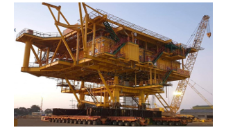 Figure 1: A project to load out the gantry using self-propelled trailers
Many leading companies in the world have approached to invest in self-propelled trailer systems. However, several companies in Vietnam also invest but are limited because of the high cost. In particular, Vietranstimex has invested a Cometto self-propelled trailer system that made in Italy [6] and is a Modular Self-Propelled Electric (MSPE) type. During operation, the Cometto system has shown many advanced features such as:
- Flexible assembly: modules are joined together by vertical or horizontal coupling depending on the size and load of packages.
- Mobile steering system: The ability to rotate the package 360 degrees when not moving and many driving modes: wheel steering, parallel steering, single-headed steering.
- The ability to shift the center of steering system in order to adjust the trailer to overcome difficult roads without interfering with the initial programming.
However, the Cometto self-propelled trailer system still presents many problems during operation, including the frequent failure of the ELS valve. Therefore, a new method was proposed in order to handle fastly the ELS valve damage. A throttle valve M is used in series with both tap J and ELS valve. Accordingly, when the ELS valve fails, no matter the status of tap J and without locking tap J, the hydraulic pump is adjusted by turning the throttle valve M only so that the system pressure, which is displayed on the driving pressure gauge, reaches to 200 bar or to 220 bar. The system works stably by those pressures. When more pressure is needed, the throttle valve M continues to be adjusted. After the throttle valve M is installed in the hydraulic system controlling the pump, the self-propelled trailer system works very stably and the proposed self-propelled trailer system has safely transported and launched a lot of oversized and overweight packages.
The remainder of the article is organized as follows: Section II describes in details the origin Cometto self-propelled trailer system and the method to enhance its performance; Section III describes in details the experimental results by applying the proposed method and summarizes the evaluation and Section IV concludes the article.
2. The Cometto self-propelled trailer system and the proposed method
Three problems discussed in this section is organized as follows: Subsection 2.1 introduces the overview of Cometto self-propelled trailer system including Power Pack Unit (PPU) and Modules; Subsection 2.2 specially describes about the main features of PPU hydraulic system; and Subsection 2.3 introduces the proposed method to enhance features of PPU hydraulic system.
2.1. The Cometto self-propelled trailer system
The system consists of main components as follows [7]:
- Power Pack Unit.
- The 4/4/3 electronic-hydraulic module (The module has 4 axes, 4 hydraulic motors, the module width is 3 meters).
- The 6/4/3 electronic-hydraulic module (The module has 6 axes, 4 hydraulic motors, the module width is 3 meters).
The PPU links one or more trailer modules together with either vertical or horizontal configurations as depicted in Figure 2.
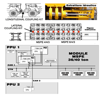 Figure 2: Main components of Cometto system
The number of PPUs and the number of modules is more or less depending on the package weight and package size. However, the system will be only controlled by one remote controller and operated by one person.
The system is operated by a Diesel engine that driving hydraulic pumps, generators and compressors. They provide hydraulic, electrical and steam power for the following main functions:
- Hydraulic drive function.
- Steering control function
- Lifting control function.
- Hydraulic brake function.
- Air brake function when connecting a self-propelled trailer and a non-self-propelled trailer.
2.1.1. The Power Pack Unit
The PPU is considered to be the brain of a self-propelled trailer system. The PPU consists of an electro-electronic control system [8], a main hydraulic system that determines the functions of the trailer. The PPU can be adjusted in the angle range of 11.8 degrees as depicted in Figure 3.
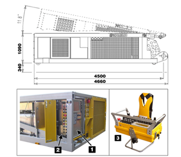 Figure 3: Power Pack and Radio Control
Between two mentioned systems, the hydraulic system, with the parameters listed in Table 1, is improved to make the trailer safer by adding a hydraulic system that controls the pump with a throttle valve. This adding valve replaces the main control valve ELS when this valve is damaged.
Table 1: The PPU hydraulic system parameters
| Variable displacement pumps | |
| Lifting and steering | A11VLO190 |
| Motorization (2 pumps) | A4VG180 + A4VG125 |
| Gear pumps | |
| Oil cooling pump | SAUER SNP3/90 |
| Pump for hydraulic oil supply to engine coolant radiators fan | SAUER SNP3/44 |
| Pump for overfeeding planetary gearboxes. | SAUER SNP3/44 |
| Pump for hydraulic oil supply to radiator fan | SAUER SNP2-17 |
Table 2: Module parameters
| WEIGHTS | MSPE 4/4/3 (4 axles) | MSPE 6/4/3 (6 axles) |
| Speed (km/h) | 0.5 5 10 | 0.5 5 10 |
| Axle load (2 suspensions), ton | 34 34 31 | 34 34 31 |
| Total gross weight, ton | 136 136 124 | 204 204 186 |
| Dead weight, ton | 1.77 | 26 |
| Payload, ton | 186.3 186.3 106.3 | 178 178 160 |
| AXLES | ||
| Number of axle lines | 4 ( 8 suspensions) | 6 ( 12 suspensions) |
| Number of driven axles | 2 | 4 |
| Number of braked axles with A.S.R. | 2 | 2 |
| PLANETARY GEARBOX | ||
| Wheel reducer (code 108.0204) | LOHMANN GFT 17 T3 9357 | |
| Number of wheel reducer | 8 | 8 |
| Variable displacement motor | A6VE 28HD1/63W | |
| Input speed | 5960 rpm | |
| Reduction ratio | 77.95 | |
| Output speed | 76,46 rpm | |
| Output torque | 13881 Nm (10237 ft.lbs) | |
| Quantity of oil per wheel reducer | 2 litres | |
| Oil type | SPARTAN EP 220~BP Energol GR-XF220 | |
| SLEW GEAR | ||
| Slew gear | IMO WD-HC 0300 | |
| Motor | PARKER VOAC F12-060-MF-INF | |
2.1.2. Modules
Modules with parameters such as in Table 2 include 6-axis type (6/4/3) and 4-axis type (4/4/3) with a maximum load for one axle of 3,4 tons. Modules are assembled by 3 types of connection such as mechanical connection, hydraulic connection and electronic connection. The connections are formed by serial configuration (back to back coupling) and parallel configuration (side by side coupling) as depicted in Figure 4.
2.2. The PPU hydraulic system.
The PPU hydraulic system [9] which is depicted in Figure5 consists of 5 pump assemblies as follows:
- One variable delivery pump A11VLO of 190cc (No. 22 in Figure 5) used for the steering and the lifting of the vehicle, and for the lifting cylinders of the Power Pack.
- Two variable delivery pumps: A4VG of 180cc and 125cc (No. 23 and No. 24 in Figure 5); used for the motorization. Being a closed circuit, each of these two pumps is equipped with an overfeeding pump.
- One fixed delivery pump of 44cc (No. 25 in Figure 5): this pump is used for overfeeding and piloting of the hydrostatic motors.
- One fixed delivery pump of 17cc (No. 26 in Figure 5): this pump operates the hydraulic oil radiator fan.
- One further double-body fixed delivery pump of 90cc + 44cc (No.27 and 27a in Figure 5)
- The 90cc pump (No. 27a in Figure 5) is used for hydraulic oil recirculation in the radiator and in the return filter (No. 11 in Figure 5).
- The 44cc pump (No. 27 in Figure 5) operates the Diesel engine coolant liquid/air radiator fans.
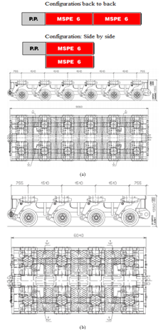 Figure 4: (a) Module Coupling and 6-axis type
(b) 4-axis type
The five pump assemblies are arranged as depicted in Figure 5 and are driven by a MERCEDES 335 KW Diesel engine. The pump assemblies are responsible for ensuring the operation of functions such as transmission, steering, lifting and braking. In particular, the hydraulic control valve ELS determines the operation of the braking, steering and lifting functions by adjusting the supply impeller A11VLO.
The hydraulic braking function: The braking function is to ensure the safety of the entire trailer system and packages. If the valve ELS is broken, the brake pressure cannot reach to 170 bar (as in Figure 6) and therefore the braking function will not work.
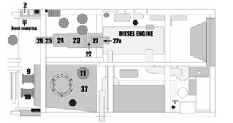 Figure 5: Pump Cluster Positions
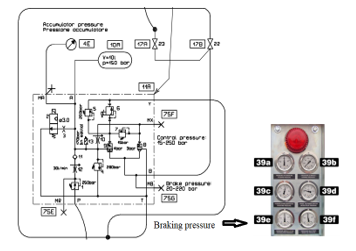 Figure 6: Diagram of the hydraulic braking system
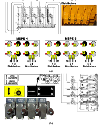 Figure 7: (a) The steering; and lifting/lowering function (b)
The hydraulic steering and lifting/lowering function: Diagram of hydraulic steering [9] and lifting/lowering function is shown in Figure 7. In addition, the hydraulic diagram for the pump A11V0 is depicted in Figure 8. The pump A11VO is used to open the steering and lifting/lowering function. This type of pump automatically changes the flow according to the load change. The working pressure of the steering and lifting/lowering function is adjusted by the proportional structure of the pressure reducing valve ELS.
If the load changes, the sensor detects and sends the signal to the central control system, then the controller processes and outputs the appropriate signal controlling the ELS regulating valve (No. 27A in Figure 8). This valve ELS will regulate the amount of oil that back to the tank in order to control the impeller corresponding to the load.
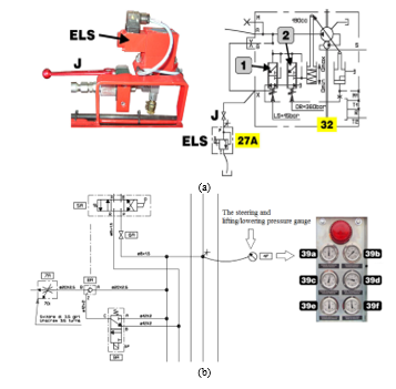 Figure 8: Valse ELS (a) and pressure gauge (b)
2.3. The proposed method
This section deals with the installation of a new throttle valve M [7] which is shown in Figure 9-b that is used to replace the hydraulic control valve ELS if it is unexpectedly damaged or failed.
The valve ELS is controlled by the electronic system with the following description:
- In the case of the diesel engine in starting and stand-by status: the system pressure approximately reaches to 15 bar during engine starting; after 5 seconds, the engine speed reaches to 900 rpm and therefore the system pressure will approximately reach to 220 bar.
- In the case of changing the direction of steering system and aligning it: the initial pressure is approximately 220 bar, the maximum pressure is 300 bar.
- In the case of lifting: The valve pressure is proportional to the load to be lifted. Working pressure is from 220 to 300 bar (approx.). Maximum pump pressure is 300 bar (approx.)
- In the case of lowering: Working pressure is from 220 to 300 bar (approx.)
- Maintain brake pressure from 170 bar to 220 bar.
- Pressure increase
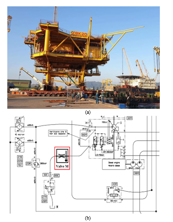 Figure 9: (a) The package is on the bridge leading to the barge (b) Install the throttle valve M into the system
In case of the valve ELS failure (pressure lack in the system), the tap J must be closed. This action allows to increase the pressure in the system to 360 bar again.
Failure of the valve ELS is an important issue because it determines all lifting, lowering, steering and braking functions when the Cometto self-propelled trailer is in operation. Therefore, the failure of this valve is very dangerous for all system because at that time the tap J needs to be closed in order to force the system to operate.
Closing the tap J will cause the pump A11VO to work at full capacity, considered to be high load, the working pressure of the pump and the piping system will be up to 360 bar (as shown in Figure 8, 39a). Diesel engine also works at high power and they often get drowned. Therefore, tap J can only be temporarily locked for a short time but not for long-term use.
Experience is learned during the actual use of self-propelled trailer system, the valve ELS often burns down when in operation because the suction coil of the valve is very hot when working due to the valve ELS is always soaked in electricity and the environmental temperature in Vietnam is much higher than in Europe (Italy, where the system is made).
In an actual coincidence case, if tap J and valve ELS are damaged at the same time (called valve leakage), all lifting/lowering, steering, braking functions stop operating and cannot be controlled. Packages will overturn if there is a difference in load at any combination in the system that makes it impossible to adjust to the balance point.
Given the nature of transportation of oversized and overweight packages, such damages are very dangerous. Moreover, when the package is lying both on the wharf and on the barge (Figure 9-a) and the tide goes up/down quickly, the incident is absolutely impossible to happen because of much more dangerous. However, if this happens, there must be immediate remedies. And the fastest way to handle when the ELS valve is damaged is an essential issue.
Based on the operating principle of the system, the function of the ELS valve is to regulate the hydraulic oil flow that controls the A11VO impeller. Therefore, the amount of control oil will be at the maximum when this valve is broken. The pump will work as in no-load state, not enough pressure for the modes of steering, lifting/lowering and braking to operate. The proposed method is ultilizing the throttle valve M (as shown in Figure 10), which is located in the main connection between tap J and the ELS valve (as depicted in Figure 9b).
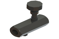 Figure 10: throttle valve M
The proposed method has improved the necessary requirements. Accordingly, when the ELS valve fails, no matter the status of tap J and without locking tap J, the hydraulic pump is adjusted by turning the throttle valve M only so that the system pressure, which is displayed on the steering pressure gauge, reaches to 200 bar or to 220 bar. The system works stably by those pressures. When more pressure is needed, the throttle valve M continues to be adjusted.
The throttle valve M theoretical basis is presented as follows:
2.3.1. Functions
The throttle valve M is responsible for regulating the flow rate in terms of the speed or running time of the actuator. The calculation method is presented in the next section.
2.3.2. Principles
The throttle works on the principle that the flow through the valve depends on the cross section (as shown in Figure 11). The oil flow qv through the gap is calculated using the Torricelli formula in (1) as follows:
![]() where: Flow coefficient. Interstitial area of the gap, [m2]. Pressure at previous and next positions of the gap [N/m2]. Density of hydraulic oil [Kg/m3].
where: Flow coefficient. Interstitial area of the gap, [m2]. Pressure at previous and next positions of the gap [N/m2]. Density of hydraulic oil [Kg/m3].
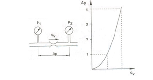 Figure 11: Difference in pressure and flow rate through the gap.
According to the flow control method, throttle can be classified into two main categories: the throttle adjusts axially (as shown in Figure 12-a) and the throttle adjusts around the shaft (as shown in Figure 12-b).
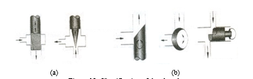 Figure 12: Classification of throtle vale
Between them, the throttle adjusts axially as shown in Figure 12-a is selected for epxeriment in this article. The specifications requirement for the throttle valve M:
- System maximum working pressure p: 300-440(Bar).
- Maximum working flow: 30 (l/ph).
- Threaded catch size: 1/2”(PT).
- Working Temperature: -25 oC ÷ 80o
- Valve Type): APT-04
- Standard size:
3. The Evaluation of Economic Efficiency
Since installing the throttle valve M into the hydraulic system controlling the pump, the self-propelled trailer system works very stable. The self-propelled trailer system safely and effectively transports a lot of petroleum packages. Some key projects had been applied the proposed method are as follows:
3.1. Hai Su Trang oil rig project in 2013:
Main task: Relocating and launching to barges the 1,700-ton upper block of Hai Su Trang rig at PTSC port, Vung Tau, Vietnam with following details:
- Relocation distance is 500 meters.
- Launching to barges.
While the trailers were moving through the bridge connecting the wharf and the barge, the ELS valve was damaged, the working pressure dropped to nearly 0 bar, the systems stopped working, unable to control the steering, lifting and braking functions. At this time, the technical worker adjusted the valve M so that the steering pressure and lifting/lowering pressure increased to 220 bar. Therfore, the system works again normally with this pressure. All actions only take 1 minute. If the valve M is not utilized, replacing the ELS valve will take 30 minutes or more, this will change the calculation parameters for the pump of bracing barges because the tide changes rapidly.
After the project is completed, our company is highly appreciated by the investors for quick action and mobility.
3.2. Su Tu Nau oil rig project in 2014:
Main task: Relocating and launching to barges the 2,200-ton upper block of Su Tu Nau rig at PTSC port, Vung Tau, Vietnam with following details:
- Relocation distance is 500 meters.
- Launching to barges.
When moving a site (site moving) from the installation location to the wharf, the ELS valve is damaged. At this time, it is very dangerous to stop and replace the ELS valve because the whole trailers and packages is lying in place for more than 30 minutes, that causes very large load impact on the road surface. Therefore, the valve M is adjusted to solve this problem within a minute and to bring the system back to normal operation.
In addition to the two typical projects just mentioned, all projects after Nov, 2014 (as listed in Table 3, 4, 5, 6) with application of the proposed method of improving the hydraulic system for Cometto self-propelled trailers have have made many investors trust our company and give the reputation of Vietranstimex is the leading company in Southeast Asia and the 34th rank in the world in the oversized and overweight transportation.
Table 3: Projects that applied the proposed method (2014-2016)
| No. | Project name; Weight (tons) | Port / Place; Time |
| 1 | Load out BK4A Jacket; 1,080 | Vietsovpetro Port – Vung Tau; Nov, 2014 |
| 2 | Site moving DSF – HRD Project; 1,360 | PTSC Port – Vung Tau; Nov, 2014 |
| 3 | Transport gantry crane; 280 | Hai Phong to Nha Trang; Mar, 2016 |
| 4 | Load out Container crane; 560 | Phu Huu Port – Ho Chi Minh; Jun, 2016 |
| 5 | Load out ST-LQ Jacket; 1,279.72 | PVC-MS Port – Vung Tau; Aug, 2016 |
| 6 | Load out ThTC3 Jacket; 992.57 | Vietsovpetro Port – Vung Tau; Aug, 2016 |
| 7 | Load out ST-PIP Module 01 Topside; 1700.29 | PTSC Port – Vung Tau; Aug, 2016 |
| 8 | Load out ST-PIP Module 02 Topside; 2820.57 | PTSC Port – Vung Tau; Aug, 2016 |
| 9 | Load out ST-LQ Topside; 2429.17 | PVC-MS Port – Vung Tau; Sep, 2016 |
| 10 | Load out BKTNG Living Quarters; 823.79 | Vietsovpetro Port – Vung Tau; Sep, 2016 |
| 11 | Site Moving Sumitomo crane; 803 | Tan Cang Port – Ho Chi Minh; Sep, 2016 |
| 12 | Site Moving Container crane; 618.62 | Tien Sa Port – Da Nang; Nov, 2016 |
Table 4: Projects that applied the proposed method (2017)
| 1 | Site Moving Container crane; 560 | ITC Phu Huu Port – HCM; Mar, 2017 |
| 2 | Load out ThTC3 Topside; 1039.94 | Vietsovpetro Port – Vung Tau; Mar, 2017 |
| 3 | Load out DKI 16 Topside; 860 | Vietsovpetro Port – Vung Tau; May, 2017 |
| 4 | Load out DKI 16 Middle; 810 | Vietsovpetro Port – Vung Tau; May, 2017 |
| 5 | Load out DKI 17 Topside; 822.4 | Vietsovpetro Port – Vung Tau; May, 2017 |
| 6 | Load out DKI 17 Middle; 750 | Vietsovpetro Port – Vung Tau; May, 2017 |
| 7 | Load out DKI 18 Topside; 908.48 | Vietsovpetro Port – Vung Tau; May, 2017 |
| 8 | Load out DKI 18 Middle; 750 | Vietsovpetro Port – Vung Tau; May, 2017 |
| 9 | Load out DKI 19 Topside; 863.95 | Vietsovpetro Port – Vung Tau; May, 2017 |
| 10 | Load out DKI 19 Middle; 750 | Vietsovpetro Port – Vung Tau; May, 2017 |
| 11 | Site Moving Container crane; 650 | Tan Vu Port – Hai Phong; Aug, 2017 |
| 12 | Load out C24-P2 Topside; 1660 | PTSC Port – Vung Tau; Dec, 2017 |
| 13 | Load out C24-P2 Jacket; 1750 | PTSC Port – Vung Tau; Dec, 2017 |
| 14 | Load out B12-13 Topside; 1360 | PTSC Port – Vung Tau; Dec, 2017 |
| 15 | Load out B12-13 Jacket; 1679 | PTSC Port – Vung Tau; Dec, 2017 |
Table 5: Projects that applied the proposed method (2018)
| 1 | Load out B12-15 Topside; 1354.32 | PTSC Port – Vung Tau; Jan, 2018 |
| 2 | Load out B12-15 Jacket; 1530 | PTSC Port – Vung Tau; Jan, 2018 |
| 3 | Load out B12-11 Topside; 1781.88 | PTSC Port – Vung Tau; Feb, 2018 |
| 4 | Load out B12-11 Jacket; 1587 | PTSC Port – Vung Tau; Feb, 2018 |
| 5 | Load out B12-17 Topside; 1396 | PTSC Port – Vung Tau; Feb, 2018 |
| 6 | Load out B12-17 Jacket; 1762 | PTSC Port – Vung Tau; Feb, 2018 |
| 7 | Site Moving Container crane; 650 | Tan Vu Port – Hai Phong; Mar, 2018 |
| 8 | Load out CTC1 Jacket; 1025.23 | Vietsovpetro Port – Vung Tau; May, 2018 |
| 9 | Site Moving Container crane; 618.62 | Tien Sa Port – Da Nang; Nov, 2018 |
| 10 | Erection packages at Paper-mill; 150 | SePon – Laos; Aug, 2018 |
| 11 | Erection packages at Paper-mill; 90 | SePon – Laos; Aug, 2018 |
| 12 | Erection packages at Hoang Van Thu Bridge Project (2 packages); 140.3 &83.5 | Hai Phong city – Vietnam; Aug, 2018 |
| 13 | Erection the center arch span bridge from the barge grillage to final elevation by strand jack system; 440.3 | Hai Phong city – Vietnam; Aug, 2018 |
| 14 | Load out CTC1 Topside; 1047.3 | Vietsovpetro Port – Vung Tau; Oct, 2018 |
Table 6: Projects that applied the proposed method (2019-2020)
| 1 | Site moving for H387 & H388 Vessel; 788.5 | Dong Xuyen Port – Vung Tau; Fed, 2019 |
| 2 | Site moving for H765 Vessel; 1057.6 | Dong Xuyen Port – Vung Tau; Fed, 2019 |
| 3 | Load out BK20 Jacket; 721.2 | Vietsovpetro Port – Vung Tau; Jul, 2019 |
| 4 | Load out BK20 Topside; 800 | Vietsovpetro Port – Vung Tau; Jul, 2019 |
| 5 | Load out SVDN Pipes; 3×2000 | PV Shipyard Port – Vung Tau; Jul, 2019 |
| 6 | Site Moving Container crane; 2×700 | Bason Port-Phu Mi; September, 2019 |
| 7 | Site Moving SVDN Jacket; 1200 | PTSC Port – Vung Tau; March, 2020 |
| 8 | Site moving, Loadout,, Launching hight speed ferry | Dong Xuyen Port – Vung Tau; May, 2020 |
4. Conclusion
The article has proposed a new method of installing the throttle valve M into the hydraulic system for the Cometto self-propelled trailer system. The method has been raised by the practical difficulties arising during the operation of the Cometto self-propelled trailer system for transporting the oversized and overweight packages. The difficulties include suspending the Cometto system, unable to control the steering, lifting and braking functions and that caused by the damage of the hydraulic control valve ELS. The sudden stop of the system makes the packages also being abruptly stopped on the road, which will put high pressure on the road surface, affecting the structure of road and the balance of barges.
With the new installation of a part in the hydraulic system, it has brought a great effect to the business, creating peace of mind for investors, increasing mobility for transport equipment and great reducing troubleshooting time when trailers are under load as well.
However, it is necessary to note that the throttle valve M only replaces the ELS valve in an emergency when the incident occurs because the M valve only works with manual adjustment. This M valve cannot replace the ELS valve completely because the ELS valve opens and closes automatically via electronic card control in the PPU. When the load changes, the ELS valve automatically adjusts accordingly. Therefore, the ELS valve replacement should be performed when the system is maintained after the project.
Moreover, authors would like to introduce in this article a kind of world-specific trailers that have been approached for a long time in the word but it is still very new in Vietnam. Hopefully, much leading transportation companies in Vietnam will equip the system in the future and put them into use more, improve efficiency, increasingly develop oversized/overweight packages transportation industry in order to reach to the world standard. Besides Cometto, there are many companies producing Modular Self-Propelled Electric (MSPE) self-propelled trailer systems such as: Golghofer, Nicolas, Kamag … Each company has different strengths but all of them enhance advanced operational features for the purpose of absolute safety for goods and people.
Conflict of Interest
The authors declare no conflict of interest.
Acknowledgment
This project is supported by Van Lang University (VLU) Electronics and Electrical Engineering Division, Ho Chi Minh City 700000, Vietnam.
- S. Gheibi, T. Banerjee, S. Ranka, S. Sahni, “Multilevel Approaches to Fine Tune Performance of Linear Algebra Libraries,” in 2019 IEEE International Symposium on Signal Processing and Information Technology (ISSPIT), 1–6, IEEE, 2019.
- L. E. Cannon, A cellular computer to implement the Kalman filter algorithm, Ph.D. thesis, Montana State University-Bozeman, College of Engineering, 1969.
- V. Strassen, “Gaussian elimination is not optimal,” Numerische mathematik, 13(4), 354–356, 1969.
- H. Prokop, Cache-oblivious algorithms, Ph.D. thesis, Massachusetts Institute of Technology, 1999.
- R. D. Blumofe, M. Frigo, C. F. Joerg, C. E. Leiserson, K. H. Randall, “An analysis of dag-consistent distributed shared-memory algorithms,” in SPAA, volume 96, 297–308, 1996.
- J. Demmel, D. Eliahu, A. Fox, S. Kamil, B. Lipshitz, O. Schwartz, O. Spillinger, “Communication-optimal parallel recursive rectangular matrix multiplication,” in 2013 IEEE 27th International Symposium on Parallel and Distributed Pro- cessing, 261–272, IEEE, 2013.
- B. Lipshitz, G. Ballard, J. Demmel, O. Schwartz, “Communication-avoiding parallel strassen: Implementation and performance,” in SC’12: Proceedings of the International Conference on High Performance Computing, Networking, Storage and Analysis, 1–11, IEEE, 2012.
- G. H. Golub, C. F. Van Loan, Matrix computations, volume 3, JHU press, 2012.
- R. A. Van De Geijn, J. Watts, “SUMMA: Scalable universal matrix multi- plication algorithm,” Concurrency: Practice and Experience, 9(4), 255–274, 1997.
- M. M. A. Patwary, N. R. Satish, N. Sundaram, J. Park, M. J. Anderson, S. G. Vadlamudi, D. Das, S. G. Pudov, V. O. Pirogov, P. Dubey, “Parallel efficient sparse matrix-matrix multiplication on multicore platforms,” in International Conference on High Performance Computing, 48–57, Springer, 2015.
- Q. Xiangzhen, “Cache performance and algorithm optimization,” in High Per- formance Computing on the Information Superhighway, 1997. HPC Asia’97, 12–17, IEEE, 1997.
- D. I. Lyakh, “An efficient tensor transpose algorithm for multicore CPU, Intel Xeon Phi, and NVidia Tesla GPU,” Computer Physics Communications, 189, 84–91, 2015.
- J. Chen, J. Fang, W. Liu, T. Tang, C. Yang, “clmf: A fine-grained and portable alternating least squares algorithm for parallel matrix factorization,” Future Generation Computer Systems, 108, 1192–1205, 2020.
- C. Yount, A. Duran, “Effective use of large high-bandwidth memory caches in HPC stencil computation via temporal wave-front tiling,” in Performance Mod- eling, Benchmarking and Simulation of High Performance Computer Systems (PMBS), International Workshop on, 65–75, IEEE, 2016.
- S. Chatterjee, V. V. Jain, A. R. Lebeck, S. Mundhra, M. Thottethodi, “Nonlinear array layouts for hierarchical memory systems,” in Proceedings of the 13th international conference on Supercomputing, 444–453, ACM, 1999.
- J. Mellor-Crummey, D. Whalley, K. Kennedy, “Improving memory hierarchy performance for irregular applications using data and computation reorderings,” International Journal of Parallel Programming, 29(3), 217–247, 2001.
- E. Athanasaki, N. Koziris, “Fast indexing for blocked array layouts to improve multi-level cache locality,” in Interaction between Compilers and Computer Architectures, 2004. INTERACT-8 2004. Eighth Workshop on, 107–119, IEEE, 2004.
- C. Kulkarni, C. Ghez, M. Miranda, F. Catthoor, H. De Man, “Cache conscious data layout organization for embedded multimedia applications,” in Proceed- ings of the conference on Design, automation and test in Europe, 686–693, IEEE Press, 2001.
- B. Recht, C. Re, S. Wright, F. Niu, “Hogwild: A lock-free approach to par- allelizing stochastic gradient descent,” in Advances in neural information processing systems, 693–701, 2011.
- W.-S. Chin, Y. Zhuang, Y.-C. Juan, C.-J. Lin, “A fast parallel stochastic gradient method for matrix factorization in shared memory systems,” ACM Transactions on Intelligent Systems and Technology (TIST), 6(1), 2, 2015.
- S. Song, J. K. Hollingsworth, “Designing and auto-tuning parallel 3-D FFT for computation-communication overlap,” in Proceedings of the 19th ACM SIGPLAN symposium on Principles and practice of parallel programming, 181–192, 2014.
- S. Lee, D. Jha, A. Agrawal, A. Choudhary, W.-k. Liao, “Parallel deep convolu- tional neural network training by exploiting the overlapping of computation and communication,” in 2017 IEEE 24th International Conference on High Performance Computing (HiPC), 183–192, IEEE, 2017.
- H. Wang, S. Guo, R. Li, “Osp: Overlapping computation and communication in parameter server for fast machine learning,” in Proceedings of the 48th International Conference on Parallel Processing, 1–10, 2019.
- J. Huang, T. M. Smith, G. M. Henry, R. A. van de Geijn, “Strassen’s algorithm reloaded,” in Proceedings of the International Conference for High Performance Computing, Networking, Storage and Analysis, 59, IEEE Press, 2016.
- R.I. Ciobanu, C. Dobre, M. Bal˘anescu, G. Suciu, “Data and task offloading in collaborative mobile fog-based networks,” IEEE Access, 7, 104405–104422, 2019.
- V. Priya, C. S. Kumar, R. Kannan, “Resource scheduling algorithm with load balancing for cloud service provisioning,” Applied Soft Computing, 76, 416– 424, 2019.
- D. Puthal, R. Ranjan, A. Nanda, P. Nanda, P. P. Jayaraman, A. Y. Zomaya, “Se- cure authentication and load balancing of distributed edge datacenters,” Journal of Parallel and Distributed Computing, 124, 60–69, 2019.
- A. Mallick, M. Chaudhari, U. Sheth, G. Palanikumar, G. Joshi, “Rateless codes for near-perfect load balancing in distributed matrix-vector multiplication,” Pro- ceedings of the ACM on Measurement and Analysis of Computing Systems, 3(3), 1–40, 2019.
- A. Mohammed, A. Eleliemy, F. M. Ciorba, F. Kasielke, I. Banicescu, “An ap- proach for realistically simulating the performance of scientific applications on high performance computing systems,” Future Generation Computer Systems, 111, 617–633, 2020.
- I.J. Sung, J. A. Stratton, W.-M. W. Hwu, “Data layout transformation exploit- ing memory-level parallelism in structured grid many-core applications,” in Proceedings of the 19th international conference on Parallel architectures and compilation techniques, 513–522, ACM, 2010.
- G. Chen, B. Wu, D. Li, X. Shen, “PORPLE: An extensible optimizer for portable data placement on GPU,” in Proceedings of the 47th Annual IEEE/ACM International Symposium on Microarchitecture, 88–100, IEEE Computer Society, 2014.
- A. Sodani, R. Gramunt, J. Corbal, H.-S. Kim, K. Vinod, S. Chinthamani, S. Hutsell, R. Agarwal, Y.-C. Liu, “Knights landing: Second-generation intel xeon phi product,” Ieee micro, 36(2), 34–46, 2016.
No related articles were found.