
Ethics as a Motivation Indicator in Second Language Vocational Digital Teaching
Volume 5, Issue 4, Page No 776-782, 2020
Author’s Name: Natalya Viktorovna Matveevaa), Ludmila Vladimirovna Makar
View Affiliations
The Linguodidactics Department, Institute of Humanities, Russian University of Transport (MIIT), 9, bld. 9, Obrazcova Street, Moscow, 127994, Russia
a)Author to whom correspondence should be addressed. E-mail: matveevanv@mail.ru
Adv. Sci. Technol. Eng. Syst. J. 5(4), 776-782 (2020); ![]() DOI: 10.25046/aj050492
DOI: 10.25046/aj050492
Keywords: College Students, Computer Games Development, Ethical Teaching Skills, Foreign Language, Out-Of-Classroom Autonomous, Activity, Teacher-Student Rapport

Export Citations
The non-selective second language course at vocational colleges and universities makes teachers strive at fostering students’ motivation to learn by choosing from a variety of enhancing factors. Teacher’s personality and skills if they comply with pedagogical ethics are considered to be inspiring for students to learn. The aim of this piloting study was to collect empirical data and ascertain the actual motivational power of ethical teaching skills when organizing and conducting autonomous learning activities for college students on the example of educational computer games.
The ethical teaching skills applied when creating and using computer games as out-of-classroom voluntary activities were conceptualized. Their possible influence on learning motivation of college students was analysed with the use of oral and written feedback procedures, and statistical data retrieved from Metrika.Yandex and students’ certificates submitted.
This allowed to determine five specific groups of students valuing the activity, which in their turn were united into two larger formations: students with distinct intrinsic motivation in the activities-related areas (60%) and socially and psychologically responsive students (40%). A possible method to evaluate statistically the efficiency of some ethical skills specified is suggested, whereas the other skills need further research under modified parameters.
Thus, ethical teaching skills are effective in the case the college students possess an intrinsic motivation in an area actualized by an activity suggested. Therefore, they are unlikely to be regarded as an independent motivator, but the indicator of a particular intrinsic motivation characteristic to a student.
Received: 31 March 2020, Accepted: 12 May 2020, Published Online: 28 August 2020
1. Introduction
This paper is an extension of work originally presented in the 19th International Symposium on Communications and Information Technologies (ISCIT) 2019 [1].
The Internet of Things (IoT) relies on smart environments comprises of wireless sensor networks [2] and personal area networks [3], [4] in which one interacts with IoT infrastructure must be uniquely identified. However, one big challenge is a need to commence seamless integration of IoT solutions with surroundings and with people [5]. Flexible materials for various IoT applications require a high level of integrity of components and mechanical robustness with repeated rolling and bending capabilities. In particular, flexible smart fitness watches, RFID tags and wearable sensors are good examples of applications that use flexible material. Besides, Elasticity and stretch-ability of materials are the key properties required by electronic devices that require large and reversible deformation. These bendable devices will also need to be versatile and may require the ability to store energy, operate with low power, and integrated with other devices and Internet of Things (IoT) applications [6]-[8].
The growth of wearable technology and the success of wearable devices has been hampered by limits such as the lack of materials and manufacturing techniques for seamless integration with electronic parts [9], the robustness in washing, drying and moulding [10], [11]. To address these challenges flexible polymer-based chipless RFID tag can be a good candidate.
In recent years, the research on wearable wireless communication and flexible devices has increased rapidly due to its usability and applications in personal communication systems [12]. For examples; Flexible antennas and Radio Frequency Identification (RFID) tags are used to keep track of several daily-routine activities, such as heartbeat and blood pressure measurement, the distance walked, the steps are taken and the calories burnt [13].
RFID Technology is growing rapidly and has significant importance in various medical, industrial and commercial applications [13], [14] such as UHF RFID tags, Chipless RFID tags and Near Field Magnetic Coupled tags are being in used in various commercial applications and medical applications [15]. In the traditional RFID technology, the backscattered field from the tags are used to transmit information by using time-variant loading or scatterer modulation [16]-[19] however, this technique requires the physical movement of the object which needs to be coded by using inductive coupling or the impedance modulation. Besides, the conventional RFID tags are active circuit, carrying a small near field chip including a power source and a memory at the centre of the body. Whereas the chipless RFID technology doesn’t require memory or a chip to save codes, instead, it uses the physical aspects of the body such as geometry and the shape to send the data [13]. The primary principle of the chipless technology is to get the resonance from the body and to encode the backscattered signal at the receiver, without additional circuitry or communication protocols [20]. Various techniques have been proposed but generally, the chipless RFID technology can be categorised into two groups. The first one is the time domain-based also called time-domain reflectometry-based designs, Surface Acoustic Wave (SAW) is an example of this. The second group is frequency domain-based RFID tags sometimes known as spectral-based tags, Frequency Selective Surface (FSS) is an example of this technique. The SAW-based chipless RFID tags are primarily worked by piezoelectricity, in which Interdigital Transducer (IDT) on the surface of piezoelectric materials are used to convert the electromagnetic wave into the acoustic wave. The acoustic waves generate the identification code while propagating through the metallic surfaces of the tag separated by a certain distance and stored on the tag [21], [22]. The SAW RFID tags are commercially available but some important issues such as the reduction in the size, increase in the read range and the data capacity needs to address 15. Besides, the FSS based frequency domain chipless RFID technique is quite promising, in which an incident electromagnetic wave is completely or partially reflected from the surface of the resonators and matches with the resonance frequency, based on the nature and the shape of the elements. The chipless RFID tags are known as passive tags as no additional power is required to operate, which make these tags promising for general IoT applications.
Passive chipless RFID tags have gained much importance as a good candidate for IoT applications because of no additional circuitry, small size, increased lifetime and the cost-effectiveness [23]. As compared to conventional RFID tags, passive tags have many significant advantages such as they are extremely cheap and can be printed over a piece of paper simple as barcodes. Moreover, the wearable applications in which washing and heating will affect the energy source, the absence of the battery and the electrical circuits make these tags promising [24].
The general structure of a chipless RFID system is an adaptive version of the Ultra-Wide Band (UWB) frequency radar [25], in which an incident electromagnetic wave from a transmitter strikes at the surface of the tag and reflect toward the reader and decoder, see Figure 1. When an incident wave Ei on the surface of the conductive element, a current is induced at the resonant frequency, 9.2GHz in the case of chipless Bow-Tie RFID tag, see Figure 1.
In this paper, a 4-bit Bow-tie shaped chipless RFID tag is designed and the transient behaviour by the application of ElectroMagnetic (EM) wave is explained. In this design, the polarization feature of non-periodic bow-tie shaped cells is taken into account to get destructive and constructive interferences. The projection of the incidents wave and reflected field and decoded in terms of bits assigned to Radar Cross Sections (RCS) [26]. The RCS is a parameter to describe the level of scattering of a target object, in this case, a tag is the target object.
 Figure 1: Structural diagram of Bow-Tie chip-less RFID system
This paper employs a simple equivalent model of the tag by using SEM-based circuit modelling. Furthermore, the coupling coefficients and the induced currents over the rings are evaluated and transient response of the Bow-Tie RFID tag is analysed. Finally, the maximum read range is calculated which is 1.8m for 0dBm and extendable to 2.14m for higher incident power, which is maximum to our knowledge for high frequencies of the range 8 to 18GHz.
The rest of the paper is organised as follows: Section II and Section III presents the tag design and its working principle, the material characterisation and optimised designs. Section IV presents the RCS measurements, which further describes the experimental verification of codes, on body RCS measurements, bending analysis and discussion. Finally, the conclusion is presented in Section V.
2. Design and Operation of Bow-Tie Chipless RFID Tag
The Bow-Tie shaped chipless RFID tag proposed in [1] is based on conventional Bow-tie shape which is opted as it has the most intense current flow on the edges of the resonating elements [27], hence cause a more intense backscattered signal. Another reason to opt this design is the fact that it provides more flexibility in designing at higher frequencies unlike octagonal [26], square [28], circular [29] and triangular [30] designs. Moreover, in Bow-tie chipless RFID tag the asymmetrical shape of the tag in which the distance between the resonators is not constant, it diminished the mutual coupling as compared to the symmetrical surfaces, placed very close to each other [31]. In this paper, a 4-bit Bow-tie chipless RFID tag is proposed and the transient behaviour of the tag is presented. The robust tag is comprised of a periodic pattern of six Bow-tie shaped cells applicable for general IoT and wearable applications.
2.1. Working Principle
The resonant frequency of the tag depends on the inductance and the capacitance between the concentric metallic bow-tie shaped elements [32]. Therefore, when an EM wave strikes at the surface of the tag it induces currents and the corresponding capacitance and the inductances are changed. The extent of the reflected or transmitted wave after falling on the surface, depends upon the placement and the geometry of the rings. Aa results, surface currents (Jin) and (Jout) are induced on the inner and outer bow-tie shaped rings, respectively, as shown in Figure 2.
In this case, the whole structure including all the surrounding bow-tie rings, interact with each other and cause the creation of the standing waves. The standing waves produced the same polarization with an odd multiple of the difference of π phase by these surface currents which are approximately equal but opposite in phase. Hence, destructive interference results in backscatter wave (Es) and create a specific frequency response. Figure 2. represents the surface current distribution over the elementary cell and all periodic bow-tie shaped rings which tends to be minimum at the inner side of the tag, at the base and ceiling while maximum and almost constant in all vicinities of the Bow-Tie tag. The area of the tag showing minimum concentration correspond to capacitive behaviour and the area where the surface current is intensive corresponds to the inductive behaviour of the tag, see Figure 2.
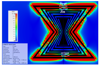 Figure 2: E-Field distribution and the directions of induced surface current (J)
3. Electromagnetic Behaviour of the Bow-Tie RFID Tag
The circuit model of the Bow-Tie chipless RFID tag provides insight into the electromagnetic response of the circuit when an incident EM wave strike at the tag and the induced current re-radiate the scattered fields. The current induced on the tag can be evaluated in different ways. One method is based on Singularity Expansion Method (SEM) in which the current induced on the tag is expanded in terms of the singularity poles of the tag. The concept of SEM has been widely used in circuit theory for a long time. Later on, this technique was used in evaluating EM response and designing of chipless RFID tags [33],[34],[35].
3.1. SEM-Based Equivalent Circuit of Chipless RFID Tag
In this paper, the SEM-based equivalent circuit of the octagonal chipless RFID tag is presented where the solution is evaluated as a collection of poles (Sn), coupling coefficient (Rn) and the entire function (Fe) in the complex frequency domain. The scattering analysis is performed by representing the chipless RFID tag with an equivalent circuit representation, see Fig. For electromagnetic response, the RFID scatterer assumed to be Perfectly Electric Conductor (PEC) in free space. Let’s N be a total number of scatterers and an incident electric field Ei strike at the surface of the tag and Es are scattered electric field with polarization vectors âi and âs, respectively. The Ei causes an induced current (Jn) on the surface and the global resonances are demonstrated in the time domain as damped sinusoidal analogous to the Complex Natural Response (CNR) of the scatterer with some weighting residue as coupling coefficients (RN). The distance between the two scatterers is optimised in such a way that the coupling between one and the alternative scatterer is very small to be negligible. Hence, the coupling between the two scatterers only at a time and ignored the effects of the others on them.
The SEM-based circuit equivalent model of the octagonal chipless RFID tag is presented in Figure 3. where, R1, R2…..RN, L1, L2,…..LN define the resistances and the inductances and C1, C2,… CN is the inductance between two consecutive scatterers for N number of resonators.
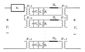 Figure 3: SEM-based equivalent circuit of Bow-Tie RFID Tag with N number of resonators
3.2. Transient Response of Bow-Tie Chipless RFID Tag
The Ei coupled to CNR’s by coupling coefficients Ri1, Ri2,….. Rin which depends on the direction and the polarization of incident electric filed, whereas Ri1, Ri2,….. Rin denotes the coupling coefficients corresponding to Es. The CNR of the model is presented by a parallel RLC circuit in series with delay line (TL) which designate the turn-on time of CNR, and Fe shows the early time response of the tag. Whereas, the input Vi and output voltages Vs are defined at the transmitting and receiving antennas ports, respectively.
Figure 4. shows the geometry of the Octagonal tag, when Ei strikes at the surface of the tag and Es electric field is scattered with polarization vectors âi and âs assuming the incident electric field as
 Figure 4: The geometry and the internal circuit modelling of the Bow-Tie RFID Tag Illuminated by an Incident Field Ei
a Dirac-delta function then the transfer function of the tag in the complex s-plane is defined as [15]
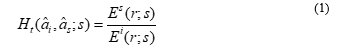 After some mathematical manipulation, the transfer function in terms of early-time response He(s) and late time response H1(s) with CNR’s can be written as [15]
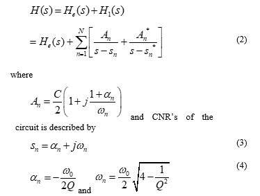 where
where
where Q represents quality factor which is kept below 0.5 and the RFID first resonator resonates at f1=ω/2π.
3.3. Evaluation of Surface Current Distribution (Jn) and the Coupling Coefficients (Rn).
The current distribution over the first resonator, the outermost octagonal ring is I1 and V1 is the induced voltage due to incident fields corresponding to the impedance Z1 of the resonator then the current distribution over the octagonal scatterers can be evaluated by discretizing the length of the ring into N number of segments [15] as
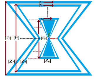 Figure 5: The induced voltages and currents distribution over the surface of the tag
![]() where corresponds to N×N matrix referred to as system impedance matrix, and are the response vector of N×1corressponding to the incident field, see Figure 5.
where corresponds to N×N matrix referred to as system impedance matrix, and are the response vector of N×1corressponding to the incident field, see Figure 5.
The CNR’s for the first scatterer is calculated from

where s0 is the initial guess of resonant frequency, by repeating this procedure more accurate values can be evaluated for the first scatterer. For Bow-Tie design, the first resonance was calculated at approximately 9.2 GHz.
The equation (5) is modified to get current distribution for the first resonator of octagonal chipless RFID tag as
![]() where Rn the residue of nth pole and Jn is the surface current distribution over the surface of the scatterer, which is evaluated in the next section. Also, The time-domain response can be obtained by applying inverse Laplace transform to (9).
where Rn the residue of nth pole and Jn is the surface current distribution over the surface of the scatterer, which is evaluated in the next section. Also, The time-domain response can be obtained by applying inverse Laplace transform to (9).
To study the mechanism of scattering by a 4-bit octagonal chipless RFID tag, the surrounding medium is supposed as a free space with permittivity ε0 and permittivity μ0, the scatterer is PEC and the thickness of the tag is very small hence considered to be zero. Consider an incident field Ei strikes and the induced current over the surface of the tag is (Jn) then the scattered field Es from the tag is either obtained from Electric Field Integral Equation (EFIE) or Magnetic Field Integral Equation (MFIE) [36]. The EFIE is used which is represented in Laplace form [37].
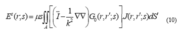 where A represents the surface area of the octagonal chipless RFID tag, , k represents the propagation constant k=s/c in the complex frequency domain and G0 defines the scalar Green’s function in the free space.
 The coupling coefficients are then evaluated by using the equations
This equation shows that the coupling coefficient depends upon Ei and natural modes at the resonant frequency.
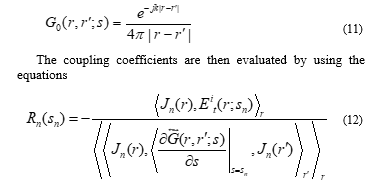
 Figure 6: The variation of the distances between consecutive Bow-Tie shaped rings
The evaluation of coupling coefficients (R1 to R4) was not easy in the case of chipless Bow-tie RFID. This is because the distance between the two consecutive bow-tie shaped rings is not constant and hence mutual coupling varies, see Figure 6. Therefore, coupling coefficients are evaluated for the values of the maximum and the minimum distances between two consecutive rings at corresponding resonance, see Table 1. The values of coupling coefficients between the first two consecutive rings are -0.010 and -0.021 calculated for the maximum and the minimum spacing of 1.2mm and 0.23mm, respectively for 9.2GHz frequency, see Table 1. Similarly, all values are calculated for corresponding resonant frequencies of 11.3, 14 and 16.9 GHz. The maximum value of Rn from the table is -0.021 which is a sufficiently low value that assures reliable reading of the coded information. To reduce the mutual coupling the average spacing between the resonators can be increased, therefore the size of the tag would be significantly increased.
Table 1: Coupling Coefficients for Corresponding Resonances
|
n |
Resonant Frequency F0n (GHz) |
Spacing Between Resonators Min to Max (mm)
|
Coupling Coefficients Minimum Rn |
Coupling Coefficients Maximum Rn |
|
| Dmin | Dmax | ||||
| 1 | 9.2 | 0.23 | 1.2 | -0.010 | -0.021 |
| 2 | 11.3 | 0.35 | 0.9 | -0.012 | -0.017 |
| 3 | 14 | 0.17 | 0.6 | -0.009 | -0.014 |
| 4 | 16.9 | 0.52 | 1.1 | -0.014 | -0.020 |
4. Flexibility and Bending Analysis
The Bow-Tie tag is designed on 13.44×11.56mm2 PET substrate of 70µm thickness with conductive gold rings varied in thickness [1].
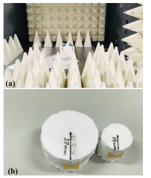 Figure 7: Chipless Bow-Tie RFID tags a) Experimental set-up in chamber b) Bending aspects of fabricated Chip-less RFID Tags at 27mm and 14mm
4.1. Experimental Setup and RCS Results
The chipless Bow-tie RFID tag is printed on a PET substrate by using Universal Laser Systems (ULS). The measurements of
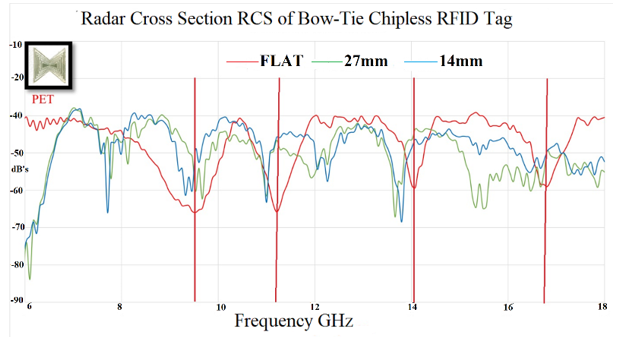 Figure 8: |RCS| measurements for the Flat, bending radius at 27mm and bending radius at 14mm
the RCS obtained by the reflections from the tag are analysed by Vector Network Analyser (VNA). For this purpose, Keysigth VNA series E5063A is used with two similar horn antennas operating at 4-18GHz frequencies. To conduct the measurement, the testing is performed in the FRANKONIA anechoic chamber, having a frequency range of 30 MHz to 40 GHz. The compact Bow-Tie RFID tag design is highly flexible and the bit codes are successfully obtained up to the bending radius of 14mm [38]. The Bow-Tie RFID tag undergoes bending for the following cases of curvatures, flat, 14mm and 27mm, see Figure 7 (b).
The Passive Bow-tie RFID tag is placed in the horizontal (H) position to perform the bending analysis for the following cases flat, 14mm and 27mm. All the testing was performed in the Frankonia anechoic chamber. One of the impacts of bending is the signal strength degradation of the backscattered waves and the significant shift in the resonant frequency. In other words |RCS| is lowered while tag undergoes bending. In this case, since the distance of the tag from the reader, is kept very small about 12cm from the transmitter, so a very small reduction in the signal strength is obtained at 0dBm power. However, the percentage shift in the resonant frequency is quite prominent especially at a higher level of bending at 14mm, see Figure 8.
Figure 8. depicts the impact of bending on the RCS obtained in the chamber. A shift of 4% from the resonant frequency is obtained, when a PET substrate-based chipless Bow-tie RFID tag undergoes bending curvature 27mm for the lower range of the frequencies 8-14 GHz, whereas, more than 10% shift is observed for higher range of frequency up to 18GHz. Hereafter, there is no noticeable reduction of the signal strength is observed because of the small distance of tag from the reader. Hence, the experimental results depict that the RCS obtained and encode in frequency signature, from the bent chip-less RFID tag fabricated on the flexible PET substrate.
5. Maximum Read Range Estimation
This section provides the maximum read range of Bow-Tie Chipless RFID tag. The complex RCS feature ( ) of octagonal chipless RFID designs can be obtained by the following equations which are described in [39].
![]() Where is associated with the measurement taken in the empty chamber, corresponds to reference value taken from define setup which could be any conductive surface, In this case, a copper square of 50mm x 50mm is taken. is associated with the simulation results for the same reference. The results achieved for all the tags show a good agreement between the measured and simulated designs.
Where is associated with the measurement taken in the empty chamber, corresponds to reference value taken from define setup which could be any conductive surface, In this case, a copper square of 50mm x 50mm is taken. is associated with the simulation results for the same reference. The results achieved for all the tags show a good agreement between the measured and simulated designs.
The radar equation is used [40] to evaluate the maximum read range of the RFID tag. For this, numerically calculated RCS are considered by using the equation is follows:
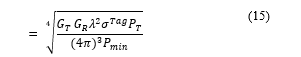 Where and are the gains of the transmitting and receiving horn antennas, is the power transmitted by VNA to measure RCS, λ is the wavelength. is the minimum power receive by receiving antenna and is the experimental values of RCS obtained from (14). For maximum read range calculations is taken for 1111bit codes, see Figure 8. flat case. The average RCS is obtained from a series of experiments [1] is around 0.02 m2. The maximum read range is evaluated for -10, -3 and 0dBm transmitted power from VNA and the maximum range observed is 1.80m and extendable to 2.15m for 3dBm power. Hence, a robust Bow-tie chipless RFID tag with transient analysis is successfully designed fabricated and tested, which is applicable for the IoT applications and the read range of the tag and bit capacity can be increased in future by using the asymmetrical property of the tag.
Table 2: Maximum Read Range Estimation
| Pmin(dB) |
GT (dBi) GR (dBi) |
λ2 (m) |
(m2 ) | PT (dB) | R (m) |
| -70 | 10 | 1.06 x 10⁻³ | 0.02 | -10 | 1.01 |
| -3 | 1.52 | ||||
| 0 | 1.80 | ||||
| 3 | 2.15 |
6. Conclusion
This paper is an extension of Novel Bow-Tie Chipless RFID tag which studies SEM-based circuit modelling of the bow-tie-shaped tag. The electromagnetic response of the tag is presented and coupling coefficients are obtained by transient analysis. The behaviour of the RFID tag is completely studied and experimentally verified for different patterns of bitstreams measured in terms of RCS. The coupling coefficients measured in this analysis evaluated for the values of the maximum and the minimum distances between two consecutive rings at corresponding resonance of 9.2, 11.3, 14 and 16.9 GHz. The maximum value of Rn from the table is -0.021 which is a adequately low value that would not impact the reliable coding of the information. Furthermore, the bending on Flexible Chip-less Bow-Tie RFID tag operating within the range of 8-18GHz are described up to the maximum bend of 14mm and the information stored on a bent chip-less RFID tag made of PET is successfully recovered. Finally, the maximum read range for the RFID tag is evaluated which is 1.8m for 0dBm power but extendable to 2.15m for higher powers. This range is maximum to our knowledge for such a high-frequency range of 8-18GHz.
Conflict of Interest
The authors declare no conflict of interest.
Acknowledgement
I would like to acknowledge the great contribution of my research colleague Panagiotis Ioannis Theoharis, for helping me in the measurements and the fabrications of the tags.
- N.V. Matveeva, “Computer Games to Fill the Gap in Learning Functional Lexis at Russian Colleges and Universities” Proceedings of 2019 International Conference “Quality Management, Transport and Information Security, Information Technologies” (IT&QM&IS), 639-643. 2019. http://doi.org/10.1109/ITQMIS.2019.8928440.
- R.R Puhan, L. Malla, S.K. Behera, “Current Ethical Issues in Teacher Education: A Critical Analysis on Pre-Service and In-service Emerging Teachers”. American Journal of Educational Research, 2(12A), 1-7, 2014. http://doi.org/10.12691/education-2-12A-1.
- M. Sultana, “Ethics in Teaching Profession” ABC Journal of Advanced Research, 3(1), 44-50. 2014. URL: http://oaji.net/articles/2015/814-1431431772.pdf
- O.S. Tsaregorodtseva, “Razvitiye pedagogicheskoi etiki uchitelya kak factor povysheniya effektivnosti obrazovatel’nogo protsessa v shole”. Ph.D Thesis, Murmansk, 2009. (In Russian).
- V.M. Grebennikova, V.V. Doroshenko “Ethics of Teaching in the Context of New Educational Paradigm”, Modern Problems of Science and Education , 1(1), 1056, 2015. (In Russian).
- I.M. Shadrina, “Model of Building the Moral Culture of a Student – Future Teacher”, The Volga district pedagogical bulletin, 6(3), 117-125, 2018. (In Russian).
- N.E. Skripova, “The professional ethics for teachers: perspective directions of the professional development system”, Professional development system scientific bases, no 2(23), pp. 28-35, 2015. (In Russian).
- E.V. Pyaterikova, “Pedagogical Foundations of Ethical Competence for Future Teachers”, Nizhny Novgorod State Linguistic University Bulletin. Issue 21. Intercultural communication and teaching foreign languages. Challenges in Education, pp. 181-188, 2013. (In Russian).
- M.V.Lamb & M. Wedell, “Cultural contrasts and commonalities in inspiring language teaching”, Language Teaching Research, 19.2, 207–224, 2015. http://dx.doi.org/10.1177/1362168814541716.
- E.A. Melyokhina, Ya.R. Bobohodzhaeva, “Motivation to Learning a Foreign Language: Pedagogical Aspect”, Teacher in Higher Education in XXI century, 1, 89-93, 2016. (In Russian)
- M. Lamb, “The motivational dimension of language teaching”, Language Teaching, 50.3, 301-346, 2017. http://doi.org/10.1017/S0261444817000088.
- N.V. Matveeva, “Professionally Oriented Vocabulary in English Classes is Truly Fascinating”, Secondary Vocational Education, 12, 10-15, 2018. (In Russian)
- J. Macmurray, “Learning to be Human”, Oxford Review of Education, 38, 2012 – Issue 6, 2012: Special issue: Learning to be human: the educational legacy of John Macmurray https://doi.org/10.1080/03054985.2012.745958
- C.A. Wolters, “Regulation of motivation: Evaluating an underemphasized aspect of self-regulated learning”, Educational Psychologist, 38(4), 189–205, 2003.
- K.A. Noels, “Learning Japanese, learning English: Promoting motivation through autonomy, competence and relatedness”, In M. Apple, D. Da Silva & T. Fellner (Eds.), Language Learning Motivation in Japan, 15–34, 2013. http://doi.org/10.21832/9781783090518-004
- A.Y. Lozovoy, E.K. Zashchitina, “Online Education: Pros and Cons”, Proceedings of 2019 International Conference “Quality Management, Transport and Information Security, Information Technologies” (IT&QM&IS), 631–633, 2019. http://doi.org/10.1109/ITQMIS.2019.8928455.
- A. Assor, H. Kaplan, and C. Roth, “Choice is good, but relevance is excellent: Autonomy-enhancing and suppressing teaching behaviors predict students’ engagement in schoolwork”, British Journal of Educational Psychology, 72, 261-278, 2002.
- H. Jang, J. Reeve, & E.L. Deci, “Engaging students in learning activities: It is not autonomy-support or structure but autonomy-support and structure”, Journal of Educational Psychology, 102, 588-600, 2010.
- S. Aydin, “Factors causing demotivation in EFL teaching process: A case study”, Qualitative Report, 17.51, 1–13, 2012.
- M. Bernaus, A. Wilson & R. C., “Gardner Teachers’ motivation, classroom strategy use, students’ motivation and second language achievement”, Porta Lingarum, 12, 25–36, 2009.
- J. Huang, T. Han, & K. Schnapp, “Do High-Stakes Test Really Address English Learners’ Learning Needs? – A Discussion of Issues, Concerns, and Implications”, International Journal of Learning and Development, 2(1), 499-508, 2012.
- V.V. Zolotarev, M.N. Zhukova, “Role Model Features in Educational Serious Games”, Proceedings of 2019 International Conference “Quality Management, Transport and Information Security, Information Technologies” (IT&QM&IS), 583–586. 2019. http://doi.org/10.1109/ITQMIS.2019.8928292