
Design and Implementation of a PLC Trainer Workstation
Volume 5, Issue 4, Page No 755-761, 2020
Author’s Name: Matthew Oluwole Arowoloa), Adefemi Adeyemi Adekunle, Martins Oluwaseun Opeyemi
View Affiliations
Department of Mechatronics Engineering, Federal University Oye – Ekiti, 371104, Nigeria
a)Author to whom correspondence should be addressed. E-mail: arowolo.oluwole@fuoye.edu.ng
Adv. Sci. Technol. Eng. Syst. J. 5(4), 755-761 (2020); ![]() DOI: 10.25046/aj050489
DOI: 10.25046/aj050489
Keywords: PLC, Ladder logic, PLC Workstation, Programming, Software

Export Citations
The Programmable Logic Controller (PLC) is an important component for industrial automatic engineering operation. Hence, the need to comprehend its basis of operation becomes an inevitable task. Some of the problems is industrial PLC is an expensive, pre-built hardware kit, acquisition of programming software and its requisite programming competence is a challenge. Thus, this paper present’s the design steps for a desktop PLC trainer workstation for industrial automatic engineering operation. Although researchers have proposed and reported several PLC trainers but they fail to discuss the hardware connection of the input/output components neither is the basic PLC automatic – operation nor PLC component symbols with description discussed. These are the areas discussed in this paper to train participant on PLC programming knowledge. The develop PLC workstation consist of push buttons and switches for input signals and for output signal buzzer, indicator lights and blower. The control aspect comprises the PLC, timer and relay. The PLC module is the MITSUBISHI FX 1S-30MR-001, the simulation software is the MITSUBISHI FXTRN-BEG-EL and the programming software is the MITSUBISHI GX Developer version 8. Authors presented two automatic control application scenarios to train participants and evaluate how the trainer is applicable to real-world situation. We conducted a survey after training to measure the impact of our approach for PLC programming knowledge for participants and result show enhanced knowledge in design step module and LL programming module significantly with our approach.
Received: 28 May 2020, Accepted: 05 August 2020, Published Online: 28 August 2020
1. Introduction
The PLC replaced the antique relay control logic in the late 1970s in the control of machines and processes [1]-[3]. Some of the benefits of the PLC over the relay control logic are flexibility, higher reliability, communication possibilities, faster response time, and easier troubleshooting [1]. Hence, it has become a vital component in the industry for engineering operation control. The PLC is a microprocessor-based controller; it receiver’s analogue and digital signal input from input component such as switches and sensors and apply instructions stored in it programmable memory to control outputs to output components such as motors, pneumatic devices and status indicator. It implement’s functions such as logic and sequence [1,4]. The rapid pace of technological development with new model and innovation of PLC technology and its flexibility has encouraged its application beyond industrial control spectrum. Therefore, the development of competence through training in the cabling, programming of PLC and its application become imperative for student and person with interest in the field of industrial automation. Nevertheless, some of the problems is that industrial PLC is an expensive, prebuilt hardware kit also, to acquire programming software and its requisite programming competence is a challenge [2].
The programming languages defined by IEC 6-1131 for PLC is the Ladder Logic (LL), Structure Text (ST), Function Block (FB) and Instruction List (IL) [3]. The PLC programming device can be a handheld device or the personal computer (PC). However, the PC is commonly used for PLC programming because it is readily available and portable. The LL is the most used programming language because it is simple to comprehend and implement [5]. Although researchers have proposed and reported several PLC trainers but they fail to discuss the hardware connection of the input/output components neither is the basic PLC – automatic operation nor PLC component symbols with description discussed. These are the areas discussed in this paper to train participant on PLC programming knowledge.
Authors in [2] described the development of an embedded PLC for teaching students. Authors combined LabVIEW software and the AVR Microcontroller with the VB modules to achieve the embedded PLC built bottle filling plant for it application. The programming language used for the embedded PLC is the FB. Although the embedded PLC setup is flexible, relatively easy and affordable to teach the basic principle for PLCs, they did not present or discuss FB program for the bottle filling application. Also, survey report of their application shows moderate performance in stability and reliability. In [6] the development of a PLC Trainer Kit Simulator Automation Lab at the Polytechnic of Sultan Abdul Halim Mu’adzam Shah (POLIMAS) was described. The training kit comprises the Omron PLC CPU unit with 12 inputs and 8 outputs control. Input and output devices are bank of switches and light indicators respectively. They used CX-Programmer for CP1E version 1.0 to program the PLC using ladder diagram and instruction list PLC programming languages. The fabrication of a multiple input/output (I/O) PLC module for educational purpose to enhance the learner’s theoretical comprehension and hands-on skill especially for programming, cabling, circuit design and problem solving is presented in [7]. Their module consists of I/O devices such as push buttons (normally open), DC motor (24V), DC relay (24V), DC solenoid piston cylinder (24V) and DC light (24V) capable of interfacing with PLC controller produced by Matsushita, Omron, Siemens. Survey report from the trainees show that 95.70 % attest to the enhancement in their theoretical comprehension and hands-on skill competence in their learning process. However, the programming aspect of the PLC is not discussed. Authors in[8] presented a PLC Based Electrical Machine Trainer Kit developed for Electrical Engineering Practices in the Department of Electrical Engineering Education at Faculty of Engineering, Universitas Negeri Yogyakarta. Their approach is research and development with reference to the ADDIE model from RobertMaribe Branch. The installed PLC is Zelio SR2.201FU and the console dimension is 44.1 cm 100 cm and 92.7 cm ×100 cm with a front tilt angle of 80 °. Authors examined the performance of trainer kit on 8 practical experiment; rotation control of DC motors; rotation control of three phase induction motor; rotation control of one phase induction motor; starting DC motor; starting 3 phase induction motor using auto-transformer; dynamic DC motor braking; DC motor braking by plugging; and braking 3-phase induction motor by DC injection. Result show the trainer kit has a good performance, indicated by the electrical components and the practical work description can function appropriately as planned. The development of an affordable and portable PLC trainer for industrial control process application is described in [9]. They used the Delta DVP14SS2 PLC, WPLSoft software and switches as inputs and pilot lamps as outputs. Instructors trained student on cabling and programming of PLC with hands-on training on Traffic light automation application. Authors carried out pre and post training evaluation for trainee and result show significant improvement of about 45.8% in the trainees’ capacity to wire and program a PLC for automation control. Authors in[10]presented a PLC educational training platform using the TM221CE16R and TM241CEC24R PLCs with TM3AM6/G analogue input/output module XX918A3C2M12 X-ray detector, XUB4APBNL2 photoelectric detector and XS8D1A1PBL5 inductive detector as sensors. They programmed HMISTU855 machine interface using the Vijeo Designer 6.2 Software. Authors presented a comparative study of the PLC programme using SoMachine Basic and SoMachine V4.3 software. A PLC training kit compact and portable for learning on industrial automation practice is presented in [11]. The hardware includes: PLC Omron CP1E-N20R, plug and play I/O interface, DC motor module, electro-pneumatic module integrated in a portable box with dimension 41 23 11.8 cm.
The objective of this paper is to present design steps for a desktop PLC trainer workstation for industrial automatic engineering operation with emphasis on hardware connection of the input/output components. We present basic PLC automatic operation such as latching and PLC component symbols with description. In order to train students and person’s with interest in the field of automatic control for industrial automation. The design and implementation comprise the cabling, programming of PLC using ladder logic with the PC, downloading and uploading the program to the PLC through USB cable and testing on the workstation.
2. Design Step
The materials for the development of the proposed PLC training workstation are: MITSUBISHI FX 1S-30MR-001 PLC, simulation software; MITSUBISHI FXTRN-BEG-EL and programming software; MITSUBISHI GX Developer version 8, Power Supply Unit, USB programming cable, switches, push buttons, blower, relay and buzzer.
2.1. MITSUBISHI FX 1S-30MR-001 PLC
Mitsubishi PLC is applied in this work to achieve the desired control specification written in LL. We used the MITSUBISHI GX Developer version 8 programming software to write the LL program. The PLC has 28 number of I/O (discrete, I = 14, O =14), 24 V DC input signal and power supply, with relay and transistor output type. Figure 1 shows the PLC diagram.
 Figure 1: Mitsubishi FX 1S-30MR-001 PLC
2.2. Power supply unit
The PLC operate on 24 V DV converted from a 220 V AC source voltage. The 24 V DC is distributed through the I/O peripherals as shown in Figure 2.
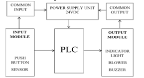 Figure 2: System architecture for the PLC trainer workstation
Table 1 presents other materials used in the setup.
Table 1: Hardware Components
| S/N | Item | Specification | Model |
| 1 | Buzzer | Active buzzer with predefined frequency (2300 ±300 Hz) | |
| 2 | Blower | Rated Voltage: 5V- 12V- 24V, Operation Voltage: 3.5-27.6V, Rated Current: 0.08-0.45A, Rated Speed:3000-5000RPM, Air Flow: 23.72-51.23CFM, Static Pressure:3.1-9.63H2O, Noise Level: 24.84-45.32dBA, Weight: 63g | |
| 3 | Relay | G2R-1-E Omron relays, Rated coil voltage: 24VDC / 110VAC. Rated switching current: 16A at 250VAC / 16A at 30VDC. | |
| 4 | Timer | Time Delay Relay Solid State Timer, ST3PA-B 0-10S Power ON Delay Timer Relay Knob Control Time Relay with Base AC 220V | |
| 5 | Push Buttons | Siemens Flush Push Button Buttons 3SB5000-OACO1 | |
| 6 | Indicator light | 16mm 12V Round Panel Mount LED Light CNGAD NXD-213 |
2.3. Means of Programming
The means of programming is an HP core i5 laptop computer with windows 10 operating system installed with MITSUBISHI GX Developer version 8 to create/edit the LL diagram, download/upload a control program into or from the PLC. The laptop and the PLC are interfaced using a USB communication cable.
2.4. Hardwired circuit
Figure 2 present’s the system architecture for the PLC trainer workstation. The hand wiring schematic of the I/O component and AC source is shown in Figure 3. Input components are connected to the PLC on the X block and output components are connected to the PLC on the Y block. The AC power source is connected to the neutral (N) and life (L) terminal on the PLC. The common terminal of the Y block of the PLC is inter-connected. Input component terminal is connected to the common and a X address on the X block of the PLC. Output component terminal is connected to 24 V DV and a Y address on the Y block of the PLC.
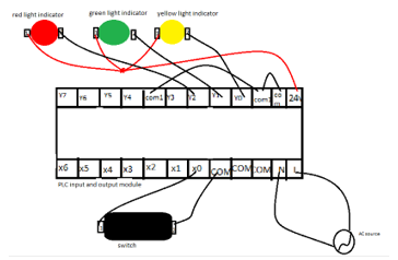 Figure 3: Hand wiring schematic of the I/O component
The hardware component and PLC are mounted on a plywood panel board with aluminium frame shown in Figure 4 with thedimension (120 60 5) cm.
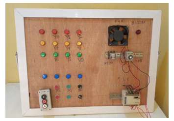 Figure 4: PLC Training workstation
2.5. Programming Language
The LL defined by IEC 6-1131 is the programming language used in this work. The LL programming structure is similar to ladder with horizontal rails and vertical rungs. In the LL structure; power flows from left horizontal rail to right horizontal rail through the connecting vertical rung. Circuit components are shown on the vertical rung in their normal condition. Every rung must specify a control operation with at least one input and output component on each rung. Input component is shown on the left and output component on the right of the rung. Same component can appear multiple time on a LL. I/O component are addressed as specified by the PLC manufacturer. The PLC reads the LL left to right, top to bottom with the last rung specified as END or RET. Table 2 below presents LL symbols with description.
Table 2: LL Symbols with description
| S/N | Symbol | Description |
| 1 | Input component, normally open contact | |
| 2 | Input component, normally closed contact | |
| 3 | Input component, rising edge detection (contact is energized when signal switch from 0 to 1) | |
| 4 | Input component, falling edge detection (contact is energized when signal switch from 1 to 0) | |
| 5 | output component | |
| 6 | instructed out component; SET means set output Y001 energized. And RST means reset output. |
The addresses used in Mitsubishi are; X, Y, M, T and C for input component, output component, internal relay, timer and counter. Internal rely number ranges from 000 – 999 and special function relay M8000 is energized by the run button of the PLC. Timer and counter have the K number that specifies the time in seconds and unit to be counted. However, conversion for timer K number to second is 0.1sec to 1 K number.
3. Methodology
Participants are taken through the step by step wring of the PLC trainer workstation and LL programming discussed above. Under lecturer supervision participant hardwired the PLC trainer work stationas shown in figure 3. To train participant on automatic control they are taken through LL programming for PLC with LL symbols with description explained above. Participant are trained on writing LL program for automatic control and are given assignment on latching procedure to develop their PLC programming skill. The participants are required to write two latching procedure with LL program using [PB1] (X20) for output ON, [PB2] (X21) for output OFF and signal lamp (Y20). Figure 5 and 6 are two random selected LL program by participant.
 Figure 5 Instructed Output Latching Procedure
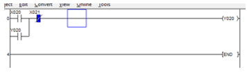 Figure 6 OR Logic with Precedence Latching Procedure
To show that the develop trainer workstation can be applied to train participants on real-world automatic control, two real-world scenarios are presented in table 3. Participants attempt the scenarios and the LL program is shown in figure 7 and 8.
Table 3: Participant Test Modules
| No | Scenario1 | Scenario 2 | |
| i. |
When push button X0 is pressed blower Y1 is switched ON and runs for 20 seconds
|
i. | When switch X2 is ON buzzer Y2 is ON for 5 seconds |
| ii. | After 20 seconds the blower goes OFF and the buzzer Y2 is ON for 10 seconds | ii. | After buzzer goes OFF LED light Y4 (green) is ON for 10 seconds |
| iii. | Step i and ii above is repeated | iii. | After 10 seconds Y4 goes OFF and Y5 (red) is ON for 5 seconds |
| iv. | The process i – iii is repeated |
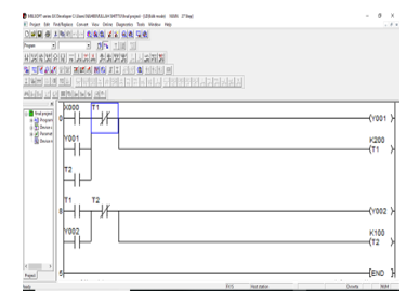 Figure 7: LL Scenario 1
 Figure 8: LL Scenario2
To measure the impact of the trainer on PLC knowledge of participants a survey was conducted after training. An observation sheet was given to participant for comment on the module of PLC technology tutored. This allowed participant to give their evaluation on each module tutored. To fill the observation sheet participant must partake in all the 3-module tutored and summary presented in section 4.
4. Results and discussion
The summary of the observation sheet filled by the 23 participant taking the course; Automation and Robotics (MTE502) in the Department of Mechatronicswhere PLC is one of its course content in the laboratory exercise is presented in table 4. The 3module tutored are reflected.
Table 4: Summary of observation sheet
| S/N | Topic | Point | |||||||
| 5 | 3 | 1 | 0 | ||||||
| Design step module | |||||||||
| 1 | Improved knowledge about PLC input and output components | 8 | 12 | 3 | |||||
| 2 | I comprehend PLC system architecture | 4 | 11 | 5 | 3 | ||||
| Design step module | |||||||||
| 3 | I comprehend the description of a PLC unit | 2 | 14 | 5 | 2 | ||||
| 4 | I comprehend PLC system hardwiring | 1 | 17 | 2 | 3 | ||||
| LL programming module | |||||||||
| 5 | I gained more knowledge about PLC input and output components symbol with description | 9 | 12 | 2 | |||||
| 6 | Improved PLC programming using LL | 6 | 11 | 4 | 2 | ||||
| Automatic control module | |||||||||
| 7 | Improved knowledge on automatic control concept such as latching and logic with PLC using LL | 2 | 11 | 7 | 3 | ||||
| 8 | I comprehend the use of timer and relay with LL on PLC | 1 | 8 | 6 | 8 | ||||
| 9 | I can independently write LL program for automatic control with PLC | 2 | 9 | 8 | 4 | ||||
Point: strongly agreed = 5; agreed = 3; disagreed = 1; strongly disagreed = 0
To categorise the participant in two categories; strongly agreed enhance knowledge ( ) and strongly disagreed enhance knowledge ( ) on PLC using the trainer. Table 5 present the percentage of and grade point on the topics.
Table 4, 5 and Figure 9 present the summary of the observation sheet for the 23 participants. This result show the participants agreed that the PLC trainer workstation enhance their knowledge on design step module and LL programming module significantly. However, about 50 % of participant did not show confidence writing LL program for automatic control independently and is evident on the automatic control module survey. This can be enhanced with further practice with Human Machine Interface (HMI) for real-time control visualization.
Table 5: Percentage of and grade point
| S/N | Topic | % Point | |
| Design step module | |||
| 1 | Improved knowledge about PLC input and output components | 86.96 | 13.04 |
| 2 | I comprehend PLC system architecture | 65.22 | 34.78 |
| 3 | I comprehend the description of a PLC unit | 69.57 | 30.43 |
| 4 | I comprehend PLC system hardwiring | 78.26 | 21.74 |
| Average point | 75.00 | 25.00 | |
| LL programming module | |||
| 5 | I gained more knowledge about PLC input and output components symbol with description | 91.30 | 8.69 |
| 6 | Improved PLC programming using LL | 73.91 | 26.09 |
| Average point | 82.61 | 17.39 | |
| Design step module | |||
| 7 | Improved knowledge on automatic control concept such as latching and logic with PLC using LL | 56.52 | 43.48 |
| 8 | I comprehend the use of timer and relay with LL on PLC | 39.13 | 60.87 |
| 9 | I can independently write LL program for automatic control with PLC | 47.83 | 52.17 |
| Average point | 47.83 | 52.17 | |
 Figure: 9 Percentage comparison of and grade point
5. Conclusion
This paper present’s the design steps for a desktopPLC trainer workstation for industrial automatic engineering operation. Although researchers have proposed and reported several PLC trainers but they fail to discuss the hardware connection of the input/output components neither is the basic PLC automatic operation nor PLC component symbols with description discussed. These are the areas discussed in this paper to train participant on PLC programming knowledge. A survey of the 23 participant taking the course; Automation and Robotics (MTE502) in the Department of Mechatronics where PLC is one of its course content presented show that 68.43 % of participant strongly agree to improvement in PLC operation knowledge. This percentage is superior tothe45.8 % presented in [9]. Hence, our approach; PLC hardware connection for input/output components, basic PLC automatic operation and PLC component symbols with description discussion with the participant improved their performance in the 3 modules evaluated. However, about 50 % of participant did not show confidence writing LL program for automatic control independently and is evident on the automatic control module survey. This can be enhanced with further practice and Human Machine Interface (HMI) for real-time control visualization.
Conflict of Interest
The authors declare no conflict of interest.
Acknowledgment
Authors like to acknowledge the staff and student of the department of Mechatronics Engineering, Federal University, Oye-Ekit for their support during this work.
- M. Barrett, “The Design of a Portable Programmable Logic Controller (PLC) Training System for Use Outside of the Automation Laboratory” in 2008 International Symposium for Engineering Education, Dublin City University, Ireland, 2008.
- K. Bhise, S. S. Amte, “Embedded PLC Trainer Kit with Industry Application” Int. J. Eng. Sci. Innovative Tech (IJESIT), 4(3), 1-9, 2015.
- C. D. Johnson, Process Control Instrumentation Technology (8th ed.), Upper Saddle River, New Jersey, Prentice Hall, 2006.
- W. Bolton, Programmable Logic Controllers, (4th ed.), UK, ELSEVIER, 2006.
- D. H. Gawali, V. K. Sharma, “FPGA Based Micro-PLC design Approach” Advances in Computing, Control, and Telecommunication Technologies” in 2009 International Conference on Communication, Computing and Electronics Systems, 2009.https://doi.org/10.1109/ACT.2009.167
- M. Mahadi, N. A. Mohd Amin, M. Ab-Rahim, M. S. Abdul Majid, “PLC Trainer Kit Simulator: An Improvement for Automation Study in Polimas” Appl. Mechanics and Mater., 786, 367-371, 2015.
https://doi.org/10.4028/www.scientific.net/AMM.786.367 - B. Ibrahim, A. A. Ahmad, T. Saharuddin, “Multiple Input/Outputs Programmable Logic Controller (PLC) Module for Educational Applications” in 2015 Innovation & Commercialization of Medical Electronic Technology Conference (ICMET), Shah Ala, Malaysia, 2015.https://doi.org/10.1109/ICMETC.2015.7449570
- S. Sukir, A. S. J. Wardhana, “Performance of A Programmable Logic Controller Based Electrical Machine Trainer Kit” J. Phys.: Conf. Ser., 1413 (2019) 012011, IOP Publishing, 2019.https://doi.org/10.1088/1742-6596/1413/1/012011
- R. Awingot, A. Albert, F. A. Oliver, “Development of a Programmable Logic Controller Training Platform for the Industrial Control of Processes” Am. Sci. Res. J. Eng., Tech. Sci. (ASRJETS), 186-196, 2016.
- C. Sărăcin, L. G. Deaconu, “Educational Platform Dedicated to the Study of Programmable Logic Controllers and the Human Machine Interface” in 2019 The 11th International Symposium on Advanced Topics in Electrical Engineering, Bucharest, Romania, 2019.
https://doi.org/10.1109/ATEE.2019.8725021 - E. S. Maarif, S. Suhartinah, “Compact Portable Industrial Automation Kit for Vocational School and Industrial Training” in 2017 International Symposium on Materials and Electrical Engineering (ISMEE), 2017.https://doi.org/10.1088/1757-899X/384/1/012011