Design of a Flapping Wings Butterfly Robot based on Aerodynamics Force

Adv. Sci. Technol. Eng. Syst. J. 5(4), 667–675 (2020);
 DOI: 10.25046/aj050480
Insect robots are always amazed by humans due to their ability to fly using a wing flapping mechanism. The butterfly robot was designed in this research based on aerodynamics and aeroelastic especially for designing a flapping mechanism due to its complexity. A butterfly wing structure was designed by considering aerodynamics forces based on assumptions. Aerodynamic equations were derived in order to obtain lift and thrust forces that acted on a small wing section. The wing was assumed to be in the Quasi-steady state when it was analyzed based on the thin airfoil theorem. Airflow was simulated in order to obtain air pressure and vertexes acting on the wing surface when it swings in the still air. By integrating the wing section’s lift force for a flapping cycle motion trajectory, the average lift force was obtained. The robot wing structure was designed based on the average lift. The real butterfly wing was used as the guideline for designing the robot wing. Each wing was fabricated from a laminar plastic sheet. Carbon fiber robs were used as an internal reinforced support structures for wing frames. The reinforced wing achieved the wing’s rigidity and was considered as a thin airfoil. The flapping mechanism was designed by using two separated servo motors because of its flexibility and performance. This mechanism enables the robot’s rotation without an extra actuator. The butterfly robot body was manufactured from the 3D printer using PLA material. The experiments were conducted to identify the robot performance. The designed butterfly robot can take off from the support platform and fly up to a certain height.
1. Introduction
Flying robots has the ability to fly up into the air and amazes human because of their behavior. There are two major types of flyable animals which are insects and birds. They use different flying mechanisms. The flyable robot uses several aerodynamic properties benefits for creating aerodynamics forces. The robot that mimics the insect is called micro air vehicles. This manuscript is an extension of work originally presented in the International Conference on Electronics, Information, and Communication 2020 (ICEIC2020) [1]. The flapping winged type robot has an advantage over a regular drone robot that uses rotating propellers. In general, flapping motion produces a larger lift force compared to a regular fixed wing at a specific angle of attack (AoA) which is important for designing a tiny flying robot with a high efficiency. Furthermore, a flapping wing robot model has the advantages over other flying robot models which are a vertical taking off from and landing to a surface, hovering with a specific height, and maneuvering in a complex environment. The autonomous flying robots were interested because it is complex to analyze, model and design robot mechanisms and hard to determine control algorithms because of the nonlinearity term. Delfly [2] Nanohumming bird [3], Purdue Hummingbird robot [4] and RoboBee [5] were popular developed flying robots that can taking off and hovering based on flapping wing mechanisms. Delfy and Nanohumming bird robot’s flapping mechanism were designed based on a crank mechanism that required one actuator to drive both wings while RoboBee and Purdue Hummingbird robot’s flapping mechanism used two separated actuators for wings. The crank flapping mechanism is easy to develop but both wings share the same angle and angular velocity trajectories yield the less degree of freedom than the two separated actuators mechanism. A crank mechanism flying robot requires an extra actuator to rotate a robot. Although these robots were successful to taking-off and hovering but the robots are small and cannot carry any large payload and the wing flapping speed is very high that consumes a lot of energy.
The aerodynamics analysis of the butterfly wing section was explained and derived at the beginning of this manuscript in order to reveal the aerodynamics of the wing. The wing aerodynamics equations are derived based on assumptions that wing was in the Quasi-steady state with thin airfoil properties. Then, the derived equations were used to design the butterfly robot’s wing. Navier-Stokes equations are used to obtain the numerical solution of the airflow against the wing. The flapping mechanism was designed based on two separate actuators mechanism which enables a rotation. The designed robot was based on a butterfly animal that has bigger wings and flaps its wings at a slower speed than other insects yield less energy consumption and more payload. Then, the designed robot can be used in the applications in Thailand such as the survey drone in the agriculture field and in the anti-terrorist application. Lastly, the butterfly wing structure, materials, flapping mechanism and the butterfly robot are designed. The robot parts were manufactured and constructed. The designed robot was experimented and the results were explained at the end of this manuscript. The overall robot design process is displayed in Figure 1.
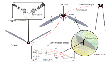 Figure 1: Overall robot design process.
2. Wing Aerodynamic Force Analysis
Aerodynamics of the butterfly wing can be analyzed by considering the small wing section along the wing span. A real butterfly wing consists of very thin membranes and a body wall made from thousands of scales and hairs, then, butterfly wing was considered as the thin airfoil. The butterfly robot model was modeled and aerodynamic forces that applied to the wing section are shown in Figure 2.
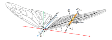 Figure 2: The butterfly robot model.
Due to the assumption that the wing’s aspect ratio is large, the air flow over each section can be cosidered as a chordwised flow. The wing is in the Quasi-steady state when parameters and time-verying components are considered as time invariant constants. The wing section is shown in Figure 3. The aerodynamics and aeroelastic forces are orthogonal to the wing section’s chord line and equal to (1). Aeroelastic happens in this calculation because the wing motion induces an added mass effect into the wing section.
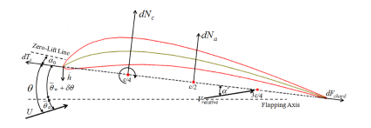 Figure 3: Wing Section
![]() where,
where,
is the circulation normal force.
is the add mass normal force.
A plunging velocity at the leading edge , the local pitch angle are created by a swing motion specific for each section. For simplicity, the wing is considered as the fixed structure and the non-span-wised bending wing. A plunging motion is a pure sinusoid function in this research and it equals to (2)
![]() where,
where,
is the maximum magnitude of a flapping motion.
is the flapping frequency.
The section aerodynamic force, , acts at the one-quarter of the chord length. A real butterfly wing that consists of a very thin membrane with the support structure was used as the designed reference for the butterfly wing. Then, the butterfly wing is modeled as the thin airfoil because a ratio of the wing thickness to the chord length is small. The normal-force was derived as (3).
![]() where,
where,
is the free stream velocity.
is the flow’s relative velocity at a 0.5 chord.
is the air density.
is the wing chord length.
is the flow’s relative angle of attack at the chord.
is the angle of the section’s zero-lift line.
is the angle of flapping axis respected to the free stream.
is a mean pitch of chord respected to the flapping axis.
Due to the properties of the aeroelasticity, the added mass of the wing section generates an apparent normal force when a wing is flapping. This normal force acts at the middle of the chord length of the wing section and equals to (4).
![]() where,
where,
is the flow’s relative velocity at half-chord.
is the relative AoA at location of chord.
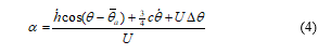
The relative angle of attack (AoA) was approximated by a diagram of velocities displayed in Figure 3 and equals to (4)
 where,
is the pitch angle change from a wing’s motion.
Clearly, the pitch angle was changed according to time, flapping frequency and the twisted angle constant per unit distance along the wing span. By assumption, the wing is an untwisted and not bended wing, thus, the flow’s relative AoA at the chord position was derived as (5)
![]() where,
where,
is the downwash velocity at the chord.
is the Jones’s coefficient.
The Jones’s coefficient [6] for the finite aspect ratio ( ) solution was derived based on the strip theory in case of the wing’s finite span unsteady vortex wake [7]. equals to the wingspan2 divided by the wing area. The dimensionless reduced frequency, , was introduced for an unsteady aerodynamics and aeroelasticity condition. Reduced frequency was related to the flapping frequency as (6).
![]() Jones’s coefficient consists of the real part and imaginary parts, thus, coefficient is a complex function. The alternative approximated formulation was proposed [8] as (7)
Jones’s coefficient consists of the real part and imaginary parts, thus, coefficient is a complex function. The alternative approximated formulation was proposed [8] as (7)
![]() The dimensionless constants and are depending on and . Scherer proposed the approximated equations of and as (8) and (9) respectively.
The dimensionless constants and are depending on and . Scherer proposed the approximated equations of and as (8) and (9) respectively.
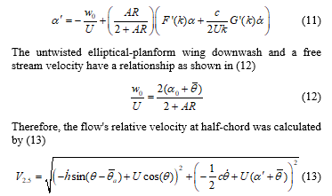
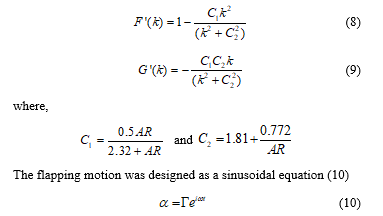 By putting (6) to (10) into (5), the flow’s relative AoA at the chord location can be approximated by (11)
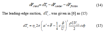
 The chordwise forces acts on the wing section. The total chordwise forces, , was the combination of 3 forces which are the leading-edge suction, camber force, and chordwise viscosity friction drag was explained as (14).
 where,
is the leading edge suction efficiency factor
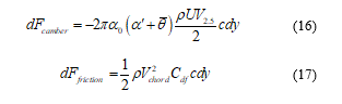
Two other chordwise forces were calculated by (16) and (17)
 where,
is the section normal flow speed.
is the skin friction drag coefficient.
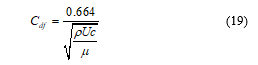
![]() The skin friction drag coefficient Cdf for a laminar flat plate skin was approximated as a function of the Reynolds number [9] which is calculated by (19) where is the air dynamic viscosity.
The skin friction drag coefficient Cdf for a laminar flat plate skin was approximated as a function of the Reynolds number [9] which is calculated by (19) where is the air dynamic viscosity.
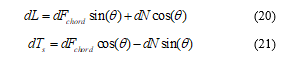
 The horizontal force and the vertical force at each strip were altered into the normal lift and parallel thrust forces equations of the free stream velocity as (20) and (21) respectively.
 Wing’s lift and thrust at any particular instant time can be calculated by integrating (20) and (21) along the wing span. The instant section’s dihedral angle in the swing motion is displayed in Figure 4 and it equals to . The average wing lift and thrust were calculated by integrating every instant wing’s lift and thrust function over one flapping period ( ), equals to (22) and (23).
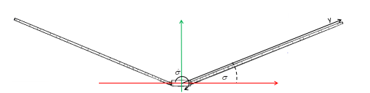 Figure 4: The section’s dihedral angle at that instant in the flapping cycle.
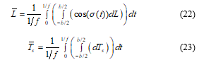 where,
is the flapping frequency.
The average lift and trust shown in (22) and (23) are the function of the flapping frequency. Therefore, wing swings with the high flapping frequency, it produces large lift force for lifting robot body up to the air. Unfortunately, when wing flaps with symmetry magnitude for the upward and downward swing, wing generated down force and lift force in the motion. Unlike the bird’s wing, the insect wing cannot be folded because the wing structure is fixed. To overcome this issue in this research, the nonsymmetric motion for the upward and downward swing is considered. The wing starts at position (a) and moves down to position (b) as shown in Figure 5. The wing has a high speed for the downward direction and a slow speed for the upward direction to generate the maximum possible lift force.
Butterfly robot will fly in the controlled wind-free indoor environment, then, the velocity of the air can be negligible. Thus, the wing motion can be considered as the laminar flat plate moves perpendicular to the air. In order to analyze the designed wing structure, the airflow against a wing is simulated. This flow is the non-reactive flow condition because the wing motion in this research was not generated from a fuel or heat which can alters the physical property of the air flow causing more shear layers in the flow. The governing Navier-Stokes (NS) equations were used as the basic flow equations. The conservation of air can be calculated from (24)
 where,
is material derivative.
is the velocity of air in x-, y- and z-axis.
is the divergence in x-, y- and z-axis.
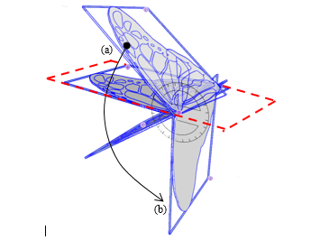 Figure 5: Butterfly wing motion
The Cauchy momentum equation of the air flow can be described as (25)
 where,
is a pressure.
is a viscous stress tensor.
is an external force vector due to the buoyancy.
For simplicity, in this research the fluid was considered as Newtonian fluid and the fluid was incompressible. Therefore, the viscous stress tensor can be estimated as (26)
![]() Navier-Stokes equations cannot be analytically solved due to the complexity [10]. The Semi-Implicit Method for Pressure Linked Equations Revised (SIMPLER) [11] method was selected in order to obtain the numerical solution of a flow. The first step in this method is to calculate the divergence-free condition pseudo-time stepping by considering (26) with the pressure-free condition and equals to (27)
Navier-Stokes equations cannot be analytically solved due to the complexity [10]. The Semi-Implicit Method for Pressure Linked Equations Revised (SIMPLER) [11] method was selected in order to obtain the numerical solution of a flow. The first step in this method is to calculate the divergence-free condition pseudo-time stepping by considering (26) with the pressure-free condition and equals to (27)
 where,
and are the estimated values of and
Equation (27) is needed to be discretized for numerical method, yield (28)
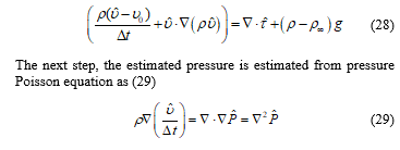 where,
is the estimated values of P
Then, value of is used in the discrete version of equation (25) to obtain the updated velocity value and used this value to update value to value via (29). Finally, the next step velocity is obtained by (30)
![]() There are several techniques to solve the numerical flow equations such as Euler, Lax-Wendroff, and 3rd – 4th orders Runge-Kutta method. In this research, the Runge-Kutta method was selected as the solver with proper boundary conditions such as flow inlet and outlet. For simplicity, the simulation is based on the Flowsquare+ flow simulator [12]. A designed wing STL mesh file was imported into the simulator, placed at the center of the airflow chamber and set perpendicularly to the x-axis. The number of grid points were 128, 64 and 64 for the x-axis, y-axis, and z-axis respectively. Air flowed in +x-direction with 5 m/s to make the simulation reaches the Quasi-steady state quickly. Dynamic viscosity was set at 1.8E-5 (kg/m/s) to simulate the atmospheric air at room temperature. The simulation results show in Figure 6 and Figure 7. Figure 6 shows that there are several vertexes happen at the back of the butterfly wing tip and the airflow simulation proves the assumption that when wing flap perpendicular to the air in the still air, it acks like a laminar flat plate. The pressure density is shown in Figure 7. From this result, the pressure condenses around the wing’s center of mass. This information will be used for the analysis of dynamics based on masses system via Euler-Lagrange equation of motion. It is clear that if one wing flaps, the reaction force is perpendicular to the wing surface and has components in both x- and y-axis. This phenomenon generates pros and cons for controlling the butterfly robot. If two wings have a symmetrical synchronized motion, then, wings generate only the left force to the robot body but if wings motion is not symmetric or asynchronized then the robot will be rotated. The diagram of wings motion is displayed in Figure 8. The averaged reaction force acting point is estimated from the pressure simulation result.
There are several techniques to solve the numerical flow equations such as Euler, Lax-Wendroff, and 3rd – 4th orders Runge-Kutta method. In this research, the Runge-Kutta method was selected as the solver with proper boundary conditions such as flow inlet and outlet. For simplicity, the simulation is based on the Flowsquare+ flow simulator [12]. A designed wing STL mesh file was imported into the simulator, placed at the center of the airflow chamber and set perpendicularly to the x-axis. The number of grid points were 128, 64 and 64 for the x-axis, y-axis, and z-axis respectively. Air flowed in +x-direction with 5 m/s to make the simulation reaches the Quasi-steady state quickly. Dynamic viscosity was set at 1.8E-5 (kg/m/s) to simulate the atmospheric air at room temperature. The simulation results show in Figure 6 and Figure 7. Figure 6 shows that there are several vertexes happen at the back of the butterfly wing tip and the airflow simulation proves the assumption that when wing flap perpendicular to the air in the still air, it acks like a laminar flat plate. The pressure density is shown in Figure 7. From this result, the pressure condenses around the wing’s center of mass. This information will be used for the analysis of dynamics based on masses system via Euler-Lagrange equation of motion. It is clear that if one wing flaps, the reaction force is perpendicular to the wing surface and has components in both x- and y-axis. This phenomenon generates pros and cons for controlling the butterfly robot. If two wings have a symmetrical synchronized motion, then, wings generate only the left force to the robot body but if wings motion is not symmetric or asynchronized then the robot will be rotated. The diagram of wings motion is displayed in Figure 8. The averaged reaction force acting point is estimated from the pressure simulation result.
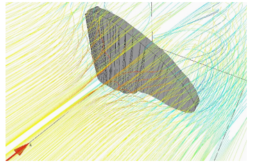 Figure 6: Air flow to a wing.
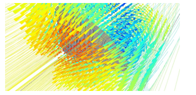 Figure 7: Pressure at a wing
3. Butterfly Robot Construction
In this section, the butterfly robot construction is explained. The first butterfly robot wing has been designed in such the way that it is 10 times larger than the real butterfly wing but keeps the wing physical properties such as a shape and the width to height proportion as shown in Figure 8. The first robot wing has a wingspan and area about 51 cm and 539 cm2 respectively. Due to the assumption from the second topic, the wing was made from a reinforced carbon fiber rods structure with a transparent laminar plastic sheet. This reinforced structure creates the wing rigidity and ensures thin airfoil properties of a flat plate skin shape. Due to the thin wing, the chord line is approximately overlap to the wing camber line. Butterfly robot has one left-wing and one right-wing, unlike a real butterfly that has two left-wings and two right-wings which generate the 3 degrees of freedoms. The designed butterfly robot creates a rotation about the flapping axis while the real butterfly creates a rotation around a single rotation point. There are two major flapping mechanisms which are one actuator and two actuators driven mechanisms. A crank-and-piston is the one actuator flapping mechanism that creates the same motion for both left and right-wings while two separated actuators mechanism can create different motions for the left-wing and the right-wing. In this research, in order to achieve the advantages of unsymmetrical aerodynamics from two wings, two servos driven mechanism was selected in order to create mismatch motions and forces between two wings. Servo motors were placed in the servos holder and attached to each wing by using a wing locker as shown in Figure 10. The complete butterfly robot is shown in Figure 11. The designed mechanism can enable robot rotation without an extra actuator such as a tail.
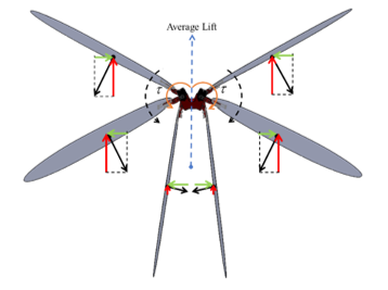 Figure 8: Two wings flapping downward motion.
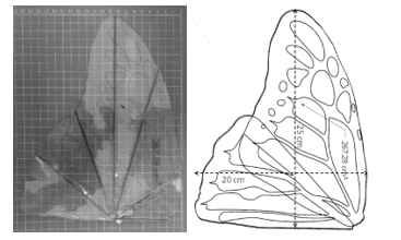 Figure 9: Prototype Butterfly Wings
The KST MS325 micro high-speed servo motors were used for the robot. The motor can generate 5.2 Kg.cm torque and achieve 60° per 0.07 second rotating speed when operated at 8.4 volts. Trust and lift forces were obtained by equations and simulations from the previous section. The completed butterfly robot dynamics was not analyzed in this manuscript because it requires masses system dynamics analysis via Euler-Lagrange or Newton-Euler methods. The completed butterfly robot mathematic model, then, will be explained in the future research. STM32 ARM Cortex-M3 is selected as the robot’s main controller operated at 72 MHz frequency via a PLL module. Servo motor and ARM controller are shown in Figure 12. A servo motor shaft position can be controlled by using the RC control signal. This control signal has a specific pulse train that has a frequency of 50 Hz, and a duty cycle varies between 5 to 10 percent of the period depends on the desired shaft location. The selected servo motor consists of a local control circuit based on a PID control algorithm, a h-bridge motor driver and the shaft position sensor. Thus, servo motor’s shaft can rotate to any desired position by using the RC control signal as long as a load torque doesn’t greater than a maximum servo torque. If the maximum torque is much greater than a load torque, the servo shaft can rotate with a constant angular velocity. Therefore, in this research, the control algorithm in the ARM controller is used for the trajectory and RC control signal generators. The servo shaft will start at the start position and then rotates to the end position with the desired speed. In this research, the swing down speed is greater than the swing up speed which will be explained in the experiments.
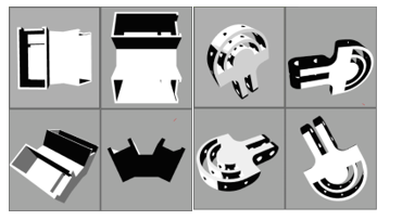 Figure 10: Servos holder (left) and Wing locker (right)
4. Experiments
The experiments on the designed butterfly robot were conducted. No power system was installed into the robot body in this research in order to reduce robot payload then the robot system was wired to the external power source. The butterfly robot was installed into a sliding rod with a support platform in order to make the robot move freely when the wings are flapped.
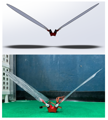 Figure 11: Butterfly robot model (top) and manufactured butterfly robot (bottom)
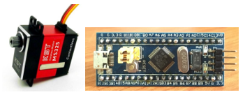 Figure 12: KST MS325 high speed servo (left) and ARM controller (right)
In the first experiment, the robot flapping mechanism was tested. The robot mechanism could flap the wings simultaneously as the desired motion but two problems occurred which were bended wing and robot rotation situation. The reinforced wings were bended due to servo torques and air pressure as shown in Figure 12. To understand this behavior each wing has to be model as a flexible robot arm which was not the aim of the wing design proposed in this research. Although, the wing was based on the real non-symmetry wing butterfly wing but the number of wings on each side was reduced from 4 to 2 wings, yield, the extra aerodynamics force and wake vertex rotate the robot body as shown in the experiment. Therefore, wings have to be further reinforced by another layer of a carbon fiber rods structure with duct tape to make a wing rigid as much as possible. The wing was redesigned to be a symmetry wing to make the air pressure condense around the center of the wing’s mass and reduce the rotation as shown in Figure 13. The modified wing was simulated in order to confirm the location of the air pressure. Then, the butterfly robot was tested again. The experiment result shows that two problems are solved as shown in Figure 14.
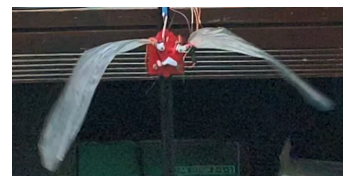 Figure 12: Bended wings situation
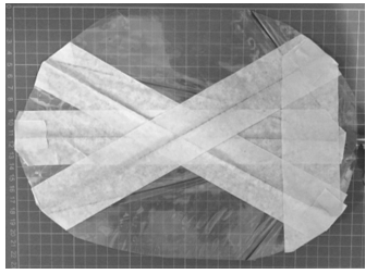 Figure 13: Redesigned and reinforced wing
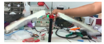 Figure 14: Unbended wings
Next, the butterfly robot was experimented. Servo motors were driven by the 50 Hz PWM signal with specified duty cycles depended on the wing locations. The driver circuit was installed to the robot power system since the ARM controller uses 3.3 volts logic while servo motors require 8.4 volts. In this experiment, the friction between the robot body and the sliding rod were neglected. The servo motor and wing lockers were printed by the 3D printer and the PLA plastic was selected as the printing material. Nuts and bolts were used to attach a wing locker to a servo horn. The total butterfly robot weight is 110 grams and the robot parameters are shown in table 1. The experiment was recorded by the Huawei P20 pro smartphone at 960 fps. In this research, the completed dynamics equation of the robot including the mass system was not considered. The coupling velocity effect and robot inertia also were neglected.
Table 1: Robot Parameters
| Part | weight | |
| 1 | Wing with wing locker | 25 g |
| 2 | KST servo motor with a plastic horn | 23 g |
| 3 | Servos holder | 9 g |
| 4 | Nuts and bolts | 5 g |
From the experiment, the butterfly robot can take-off from the support platform, fly up when wings swing down and fall back to the platform when wings swing up. It is clear that the robot wings can generate the average lift force is greater than 1.0791 N which is enough lift force to lift robot up from the support platform. The lift force can be simply estimated from the combination of the maximum torque generated from the servo motors acting at the center of the air pressure estimated from the simulation. The robot starts moving slowly from the platform then the speed is increasing and reaching the maximum acceleration when both wings are parallel to the ground and robot. Then, the robot starts moving slower until it stops at the maximum height as shown in Figure 15. The estimated lift force, if the coupling velocity effect and inertia is neglected, is about 5.4 N. At this point, the robot can reach the maximum body acceleration of 0.93 m/s. The robot can fly up to about 10 centimeters above the support platform in 1.02 seconds as shown in Figure 16. Although, in the experiment, the robot shows the success of take-off and fly up to certain height, but when the robot swings up wings, the robot drops down quickly because wing’s downforce combined with the robot weight as shown in Figure 17. This situation makes the robot drops to the platform faster when wings swing up than the robot reaches the maximum height when wings swing down. This problem has a severe impact if the butterfly carries payload such as battery and other electronic circuits. In order to overcome this problem, the wings motion is needed to be modified.
5. Conclusion and Future Work
A butterfly robot wing section’s aerodynamics and aeroelastic are analyzed, estimated and derived in order to obtain a wing behavior. Lift and thrust are important for this research because they are critical of designing a robot wing. After wing section’s lift and thrust forces were obtained, the average lift and thrust can be calculated by integrating all small wing section’s forces in particular time over one flapping motion period. Navier-Stokes equations are used to simulated the air pressure acts on the wing when swings in the still air.
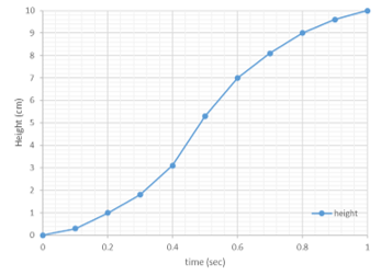 Figure 15: Height of the butterfly robot in the experiment.
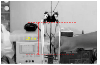 Figure 16: Maximum height.
The SIMPLER algorithm is used to obtain the numerical solution of Navier-Stockes equations. The real butterfly wing properties and dimension was used the reference for designing the desired robot wing. A laminar plastic sheet was used to mimic butterfly wing membranes properties while the reinforced fiber carbon rods was used to create wing wall structure like the scales and hairs in the butterfly wing. Thus, the designed wing was considered as a thin airfoil with laminar skin properties. A flapping mechanism was constructed from two servo motors to create flexible motions between two wings and enhance overall robot performance. The butterfly robot parts were designed and manufactured. In the first experiment, the designed wing was bended occurred from the servo torques and air pressure due to the wing material. Then, the wing was redesigned to be a symmetry wing and reinforced to reduce a bend. The experiment shows that the butterfly robot can take off from the platform and fly up to a certain height before it goes back down to the platform.
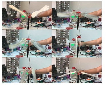 Figure 17: Experimental Result.
In this research, masses, inertias and the coupling velocity effect on the butterfly robot system were not considered. The standalone butterfly robot with payload will be designed and the completed butterfly robot dynamics will be derived using the Euler-Lagrange equation of motion. More experiments will be conducted in future work.
Conflict of Interest
The authors declare no conflict of interest.
- K. Sukvichai, K. Yajai, “Aerodynamics Force Analysis for Designing a Flapping Butterfly Robot Wing” in International Conference on Electronics, Information, and Communication 2020 (ICEIC2020), Barcelona, Spain, 2020. https://doi.org/10.1109/ICEIC49074.2020.9051389
- G. De Croon, K. De Clercq, R. Ruijsink, B. Remes, C. de Wagter, “Design, aerodynamics, and vision-based control of the delfly” International Journal of Micro Air Vehicles, 1 (2), 71–97, 2009. https://doi.org/10.1260/175682909789498288
- M. Keennon, K. Klingebiel, H. Won, “Development of the nano hummingbird: A tailless flapping wing micro air vehicle,” in 50th AIAA aerospace sciences meeting including the new horizons forum and aerospace exposition, Nashville, TN, USA, 2012. https://doi.org/10.2514/6.2012-588
- J. Zhang, F. Fei, Z. Tu, X. Deng, “Design optimization and system integration of robotic hummingbird,” in 2017 IEEE International Conference on Robotics and Automation (ICRA), Singapore, Singapore, 2017. https://doi.org/10.1109/ICRA.2017.7989639
- K. Y. Ma, P. Chirarattananon, S. B. Fuller, R. J. Wood, “Controlled flight of a biologically inspired, insect-scale robot” Science, 340(6132), 603–607, 2013. https://doi.org/10.1126/science.1231806
- R. T. Jones, The Unsteady Lift of a Wing of Finite Aspect Ratio, NACA Report No. 681, 1940
- T. Theodorsen, General theory of aerodynamic instability and the mechanism of flutter, NACA Rept. 496, 1935.
- J. O. Scherer, Experimental and Theoretical Investigation of Large Amplitude Oscillating Foil Propulsion Systems, Hydronautics Incorporated, Research in Hydrodynamics, Technical Report 662-1, Laurel, Maryland, USA, 1968.
- S. F. Hoerner, Fluid-Dynamic Drag: Theoretical, experimental and statistical information, Hoerner Fluid Dynamics; Second Edition Reprint edition , 1992.
- L. C. Fefferman, “Existence and Soothness of the Navier–Stokes equation”, Millennium Prize Problems—Navier–Stokes Equation, Clay Mathematics Institute, March 27, 2017, retrieved 2017-04-02, [Online] Available: http://www.claymath.org/sites/default/files/navierstokes.pdf [Accessed: 7- Jul- 2020]
- S. Hosseinzadeh1, R. Ostadhossein, H.R. Mirshahvalad, J. Seraj, “Using Simpler Algorithm for Cavity Flow Problem” Mechatronics and Applications: An International Journal (MECHATROJ), 1(1), 55–63, 2017. https://doi.org/10.2139/ssrn.3438116
- Flowsquare+, Available: https://fsp.norasci.com/ [Accessed: 7- Jul- 2020]
No related articles were found.