Modelling and Simulation of 3-DOF Lower Limb Rehabilitation Robot using Force Feed Forward Control
Volume 5, Issue 4, Page No 626-632, 2020
Author’s Name: Pham Van Bach Ngoc1,a), Le Thi Hong Gam2,3, Dam Hai Quan3,4, Bui Trung Thanh3, Nguyen Luong Thien1
View Affiliations
1Space Technology Institute, Vietnam Academy of Science and Technology, Ha Noi, 100000, Vietnam
2Faculty of Physics, Thai Nguyen University of Education, Thai Nguyen, 250000, Vietnam
3Mechanical Engineering, Hung Yen University of Technology and Education, Hung Yen, 160000, Vietnam
4Electronics Telecommunications, Thai Nguyen College of Economics and Finance, Thai Nguyen, 250000, Vietnam
a)Author to whom correspondence should be addressed. E-mail: pbngoc@imech.vast.vn
Adv. Sci. Technol. Eng. Syst. J. 5(4), 626-632 (2020); ![]() DOI: 10.25046/aj050474
DOI: 10.25046/aj050474
Keywords: Lower Limb Rehabilitation robot, Perceiving reality, Force control, 3-DOF, Feed forward control.

Export Citations
This research the authors design the intelligent control for 3-DOFs lower limb rehabilitation robot base on the complex dynamics equation. The Force Feed-Forward Method (FFM) is promote to control the of 3-DOFs lower limb rehabilitation robot including dynamics characteristics. The robot can sense the force of the therapist which exerted on the robot and patient’s leg, then produces necessary forces through joints at the hip, knee, and ankle. The force feedforward controller is used to compensate the force generated by the therapist to perform patient-active exercises. In this paper, firstly authors briefly introduce 3-DOFs lower limb rehabilitation robot, next the kinematics and dynamics equation of 3-DOFs lower limb rehabilitation robot established base on Lagrange-Euler method are presented, and then the control method is introduced. Last, the performance of the proposed control methods has been confirmed by numerical simulations of the robot in all three joints: hip, knee, and ankle.
Received: 13 June 2020, Accepted: 22 July 2020, Published Online: 25 August 2020
1. Introduction
The rehabilitation for patients after stroke using rehabilitation robot has three stages, early rehabilitation stage, intermediate training stage, and advanced training stage. In order to get a satisfying control effect, various control methods have been used for Robot which is suitable for each stage of the rehabilitation process. In the early rehabilitation stage, the position control strategy with the trajectory tracking control method is appropriate to continue repetitive passive exercises. After the early rehabilitation stage with continued repetitive passive exercises following the desired trajectory, the patient’s movement ability and muscle strength could be partial recovery. From this time, the fixed exercises can cause negative reactions, limiting creativity, proactive and active training of patients. Thus, the force control method aims to create the interaction between patient and robot is a very important requirement in this phase of training. In [1], the authors proposed a new method to control the force when the patient performs lower limb extensions. The aim of this control method is increasing real-time resistance to lower limb force asymmetry. The force-position hybrid control method in high rate is applied in Rutgers Ankle system [2] to resistive force on the foot of the patient to perform virtual reality-based exercises. In [3] authors use the combination of impedance controller and PD controller to control hip, knee, ankle joint of a 3-DOF rehabilitation robot. However, with the impedance controller, its parameters directly affect the effectiveness of the patient’s training. If parameters of the impedance controller are low, the patient’s foot motion may be out of range of physiological motion. Conversely, if parameters of the impedance controller are high, it can reduce the patient’s proactive training [4]. A force feedback system with sensors/observers and encoders can measure the angle of rotation of the joints and can transfer feedback forces to the controller to help the robot perceiving reality and supporting for patients [5]. Force feedback control has many advantages and has been studied worldwide for upper limb exoskeleton [6]. For the lower limb rehabilitation robot, several studies using a force feedback controller have been researched and developed. In [7], the exoskeleton has six flexible force sensors are placed in its shoe and two load cells are mounted between the end of the piston rod and the lower leg joint. Force feedback control is realized by comparing ground reaction force and applied force of the hydraulic cylinder. A force control strategy is developed in [8] to exert user-denied assistive force. The force controller involves two sets of PD plus feed-forward controllers corresponding to low- and high-force ranges, in which the interaction force between the subject and the robot (the feedback force) is calculated based on the Hooke’s law. In [9], the authors introduced a rehabilitation robot which uses a force-position hybrid fuzzy controller to limit movement in the desired direction, while maintaining a constant force along the moving direction. The position and direction of movement of the patient’s foot are collected, after which a resistance force is used to rehabilitation for stroke patients. The selection of impedance parameters is not rooting to make. These parameters need to be re-selected during the training process to suit the patient’s ability and progress [10]. Therefore, it is really necessary to have adaptive control strategies to improve the dynamic control performance of the rehabilitation robot. In [11], “robot-in-charge” and “patient-in-charge” control strategies were applied for LOPES, in which an impedance controller is used to improve the proactive training of the patient. This study’s result shows that the assistive force from the robot is effectively delivered to lower-limbs and the force feed-forward controller can be used to improve the force control performance of the lower limb rehabilitation robot. In [12], authors presented the structure of a novel force-position hybrid controller to encourage patient activeness to gait rehabilitation using driven gait orthotics. In this research, the proportional derivative (PD) close loop position controller and forced controller are applied. Impedance control strategy is a great approach for encouraging the patient’s active performing and real-time adjust the manipulator’s position and interactive force. In [13], the authors proposed a position-force controller, applied to gait rehabilitation robot, ALEX. With this controller, ALEX can guide patients to move in physiological trajectories.
This paper focus on develop a new control method Force Feed-forward for 3-DOFs lower limb rehabilitation robot for perceiving reality. The force feed-forward controller is designed for robot system can track the position, magnitude, and direction of the contact force between the patient’s lower limb and the robot. Moreover, it can produce necessary force through joints at the hip, knee, and ankle. To accomplish this task, we considered a problem, which consists of two steps. Firstly, the therapist exerts a force at links of the robot, the force is measured by force sensors placed at there. Meanwhile, the angular joint trajectories are determined by encoders located at joints. Secondly, a force feed forward controller is used to control DC motors located at joints to compensate the force generated by the therapist to perform patient-active exercises. Furthermore, force sensors also measured the force exerted by the patient’s lower limb as the input signal of the FFM controller. Finally, numerical simulation results of the robot system with FFM controller will indicate whether the controller has achieved the desired control performance. Moreover, the simulation result is used to estimate the maximum torque of a DC motor for the next design steps of robot control.
2. Mathematical model
2.1. Robot’s mechanism
The mechanical structure of the robot provides supports for rehabilitation training. It is a serial robot that has three main joints of the lower limb, including a joint at the hip, a joint at the knee, and a joint at the ankle with three links: base link, thigh, leg, and a foot platform. Movement of each joint is driven by a geared DC motor. The mechanism of Robot is shown in Fig. 1. The linkage diagram of 3 DOFs rehabilitation Robot is shown in Figure 2. A coordinate system is attached to each link of the Robot. The coordinate system is attached to the base link with its origin located at the hip joint and axis pointing to the right. This coordinate system coincides with the base coordinate system . Because all of the joints axes are parallel to each other, so all the twist angles and translational distances are zero. To perform force control for the robot using FFM control method, three DC motors are installed at joints with encoders are used to measure rotation angle, and force sensors are used to measure the force exerted by physiotherapists in training stages or force exerted by the user’s foot in practice stages.
2.2. Kinematic model
Figure 2 show the linkage diagram of 3-DOFs rehabilitation Robot, the Denavit-Hartenberg (D-H) parameters of Robot are given in Table 1, where the parameters are constant, the variables vary by rotation around the .
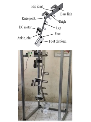 Figure 1: Mechanism of 3-DOF Rehabilitation Robot [1]
Table 1: D-H Parameters of 3-DOF Rehabilitation robot
| Joint | ||||
| 1 | 0 | 0 | ||
| 2 | 0 | 0 | ||
| 3 | 0 | 0 |
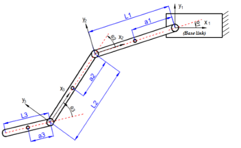 Figure 2: Linkage diagram of 3 DOF Rehabilitation Robot
The Denavit-Hartenberg transformation matrices are derived by substituting the D-H link parameters into equations (1) and (2), [14]:
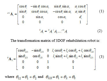 where and
From equation (3), we can get the direct kinematic model and inverse kinematic model of Robot.
2.3. Dynamic model
The dynamic model of 3DOF Robot is written in matrix form as [14]:
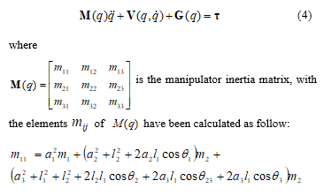
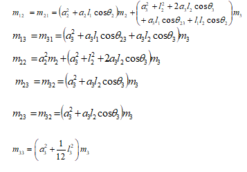 where the parameters , are the mass and the length of link , respectively;
is the velocity coupling vector, the elements of vector have been calculated as follow:
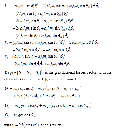
is vector of generalized Lagrange coordinates,
is the vector of generalized forces.
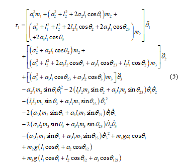
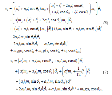
Substituting matrix , vector and vector into equation (4), the torques are calculated as follow:
 3. Design the force feed-forward controller
Rewrite general equation of motion of 3-DOF Rehabilitation Robot as:
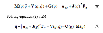 where is control torques vector, is Jacobian sub-matrix, which is used to transfer force value from the task space to the joint space, is force exerted vector.
In the intermediate training stage, the task of the controller is to produce a reasonable interaction between the patient and the Robot. To accomplish this task, in the same way, we built a FFM controller for an upper limb exoskeleton in our previous research [14], we considered a problem, which consists of two steps:
Step 1: In the beginning, the therapist moves Robot by rotating its joints following the desired loading motion. The force of the therapist is measured by force sensors placed there and it is generated to compensate for weight of the robot and the force of loading. At the same time, the angular joint trajectories are determined by encoders located at joints.
Step 2: When the robot becomes active, control torques the force, which is measured by force sensors, is used as the input of the force feedforward controller to compensate the force generated by the therapist to perform patient-active exercises. Moreover, force sensors also measured the force exerted by the patient’s lower limb and sent these forces to the input of the FFM controller. In this step, the force exerted by the therapist is desired to decrease to zero and the force exerted by the patient’s lower limb is considered as a disturbance. The target of the control is to cancel the disturbance.
From their problem, the feedforward control approach with the formula yield:
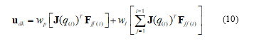 where joints angles are measured by encoders and force of the therapist or the patient’s lower limb are measured by force sensors and are constant.
The block diagram of the FFM controller shown in Figure 3.
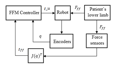 Fingure 3: Block diagram of the FFM controller
The FFM controller block is designed to perform two tasks: trajectory tracking and force control. There are two loops in the block diagram above. The inner loop is used to feedback data acquiring from encoders to implement trajectory tracking control. The outer loop is used to apply force control. The block is used to transfer force value from the task space to the joint space.
4. Numerical simulation of the force feed-forward controller
Based on the controller proposed in section III, the numerical simulation of robot kinematic, dynamic, and controller are conducted on the MATLAB/Simulink software to evaluate the performances of the proposed force controller. In the simulation program, valuable system parameters are listed in Table 2, where the parameters is the total mass of link, the motor, and the joint of stitch ; the length of link ; ; is the gear of motor.
Table 2: Simulation parameters of 3-dof rehabilitation robot
| Parameter | |||
| 3.2 | 3.1 | 0.25 | |
| 0.4 | 0.48 | 0.33 | |
| 0.2 | 0.24 | 0.165 | |
| 19 | 19 | 19 |
Step 1: In this step, based on the desired loading motion, variables , are given as follows:
![]()
where is time, are angular velocities of joints, in this simulation their values are chosen as and the gains .
The force is an unknown parameter and measures by force sensors. In reality, this force may include force exerted by the therapist, force exerted by the patient, and the weight of the patient’s foot. In this work is desired to decrease with time as expressed as:
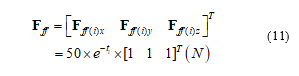 Simulation results are shown in figure 4 to figure 9, in case of applying force to foot platform link to rotate the ankle joint, the force exerted and the respective motion of the link are shown in figures following. In this simulation study, the motion of the foot platform is investigated at its center of gravity.
Fig.4 to Fig.6 shows that when the therapist applies training activity, the foot platform of the robot moves according to the trajectory in the XY plane. Fig.7 to Fig.9 shows that at the beginning of motion, the force exert by the therapist is maximum because of the foot platform is in the static state and start to move. This force decrease to zero when the platform moves to the end of the trajectory. In this step, the trajectory is sensed by the encoder, and the force exerted by the therapist is sensed by the force sensor.
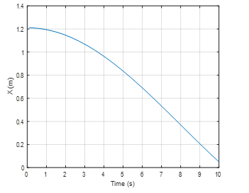 Fingure 4: Motion of the footplatform in X axis
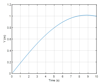 Fingure 5: Motion of the footplatform in Y axis
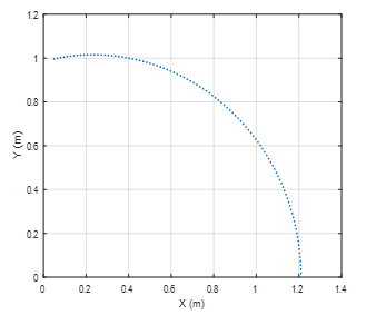 Fingure 6: Motion of the footplatform in XY plane
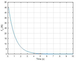 Fingure 7: Force in X direction
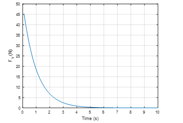 Fingure 8: Force in Y direction
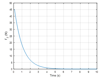 Fingure 9: Force in Z direction
There are initial conditions for the calculation of control torque in step 2.
Step 2: In this step, when the force decrease to zero, the force feedforward controller computed the control torques to compensate force. By using the equation (15), the control torques at the ankle joint in directions of the base coordinate system are shown in figures 10, 11 and 12, respectively.
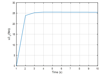 Fingure 10: Control torque in X direction
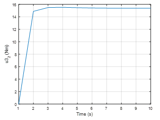 Fingure 11: Control torque in Y direction
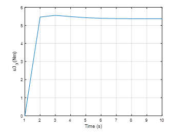 Fingure 12: Control torque in Z direction
The above results show that when the force decreases, the controller has calculated and created an increasing control torque to compensate for the reduced force. In the beginning, , the force exerted is maximum , the control torque is minimum, it is zero. In the period of 0 to 3 seconds, the force decreases, the control torque increases. When the the control torque is maximum with an approximate value of in the direction, equal to in the direction and equal to in the direction. The maximum value of control torque will be kept stable during the operation of the robot. During this process, if the patient’s lower limb actively exerts a force on the robot, this force is measured by the force sensors and sensed to the controller input. The force exerted by the patient’s lower limb is considered as a disturbance, which is canceled by the FFM controller. However, this feedforward control still has some disadvantages and need to be evaluated in a real model to adjust the parameters towards a more realistic control.
5. Conclusions
In this paper, an advanced method for force control of a 3-DOF lower limb rehabilitation robot for perceiving reality using Force Feed-forward Model was presented. The robot system can sense the force feedback from reality and apply torque through joints hip, knee, and ankle. When the therapist or patient exerts a force at the robot’s links, the exerted force is measured by force sensors placed at there and used for computing torque generated at the joints based on the configuration of the robot. When the exerted force decreases, the FFM controller was used to compute and compensate the force generated by the therapist to perform patient-active exercises. Numerical simulation results showed that the computed force control and corresponding loading motions. The results could be used to estimate the maximum moment of motors for the design steps of the robot control. In future work, we intend to present some experimental test results to compare with the numerical simulation results, which have just been presented in this paper.
Conflict of Interest
The authors declare no conflict of interest.
Acknowledgment
This work is funded by MOET project under grant number B2018-SKH-04
- A.M. Simon, R.G. Brent, D.P. Ferris, “Symmetry-based resistance as a novel means of lower limb rehabilitation,” Journal of Biomechanics, 40 1286–1292, 2007, doi:10.1016/j.jbiomech.2006.05.021.
- E.D. Judith, J. Latonio, C. Grigore and R. Boian, “Post-Stroke Rehabilitation with the Rutgers Ankle System: A Case Study,” Virtual and Augmented Reality, 10(4), 416-430, 2001, doi:10.1162/1054746011470262 .
- H.D. Trung, T.D. Vu. “A Simple Control Method for Exoskeleton for Rehabilitation,” SSRG International Journal of Electrical and Electronics Engineering (SSRG-IJEEE), 4(8), 7-12, 2017. doi:10.14445/23488379/IJEEE-V4I8P102.
- L.L. Cai, A.J. Fong, C.K. Otoshi, Y. Liang, J.W. Burdick, R.R. Roy, “Implications of assist-as-needed robotic step training after a complete spinal cord injury on intrinsic strategies of motor learning,” 26, J Neurosci, 2006, doi:10.1523/JNEUROSCI.2266-06.2006.
- C. Perry et al, “Upper arm power exoskeleton design,” IEEE/ASME Transactions on Mechatronics, 12(4), 408-417, 2007,
doi:10.1109/TMECH.2007.901934. - H. Lo and S. Xie, “Exoskeleton robots for upper-limb rehabilitation: State of the art and future prospects,” Med Eng Phys, 34, 261-268, 2012, doi:10.1016/j.medengphy.2011.10.004.
- S. Yusuf et al., “Force Feedback Control of Lower Extremity Exoskeleton Assisting of Load Carrying Human,” Applied Mechanics and Materials, 598, 546-550, 2014, doi:10.4028/www.scientific.net/AMM.598.546.
- G. Chen, P. Qi, Z. Guo, Y. Haoyong, “Mechanical design and evaluation of a compact portable knee–ankle–foot robot for gait rehabilitation,” Mechanism and Machine Theory, 51–64, 2016, doi:10.1016/j.mechmachtheory.2016.04.012.
- B. Koopman et al, “Selective control of gait subtasks in robotic gait training: foot clearance support in stroke survivors with a powered exoskeleton,” Journal of NeuroEngineering and Rehabilitation, 10, 2013, doi:10.1186/1743-0003-10-3.
- M.S. Ju et al., “A rehabilitation robot with force-position hybrid fuzzy controller: hybrid fuzzy control of rehabilitation robot,” IEEE Trans Neural Syst Rehabi Eng, 349–358, 2005, doi:10.1109/TNSRE.2005.847354.
- H. Valleryet al., “Reference trajectory generation for rehabilitation robots: complementary limb motion estimation,” IEEE Transaction on Neural Systems Rehabilitation Engineering, 17(1), 23–30, 2009, doi:10.1109/TNSRE.2008.2008278.
- M. Bernhardt et al., “Hybrid force-position control yields cooperative behaviour of the rehabilitation robot LOKOMAT,” Proceedings of the IEEE 9th international conference on rehabilitation robotics, 536–9, 2005, doi:10.1109/ICORR.2005.1501159.
- S.K. Banala, S.K. Agrawal, J.P. Scholz, “Active Leg Exoskeleton (ALEX) for gait rehabilitation of motor-impaired patients,” Proceedings of the IEEE 10th International Conference on Rehabilitation Robotics (ICORR), 401-407, 2007, doi:10.1109/ICORR.2007.4428456.
- T. Lung-Wen, The Mechanics of Serial and Parallel Manipulators, Wiley-Interscience Publication, 1999.
Citations by Dimensions
Citations by PlumX
Google Scholar
Scopus
Crossref Citations
No. of Downloads Per Month
No. of Downloads Per Country