Damage Accumulation Model for Cracked Pipes Subjected to Water Hammer

Adv. Sci. Technol. Eng. Syst. J. 5(4), 523–530 (2020);
 DOI: 10.25046/aj050462
During service, oil and gas pipelines may be exposed to cyclical loads during service, which may lead to a structural failure. Failure is due in most cases to cracks in the structure. Mechanics of the propagation of surface cracks pose a serious challenge and, therefore, models are required to help analyze it. In this study, a nonlinear model is proposed to estimate the accumulation of fatigue damage in the case of defected pipes subjected to a water hammer. The studied pipes are in the presence of a semi-elliptical longitudinal surface crack. This numerical model allows the load sequence to be considered when the structure is under variable amplitude loading. The validated model is used in a parametric analysis, the purpose of which is to determine the influence of the fluid transported and the defect parameters on the evolution of the accumulated damage. The results allow the conclusion of the parameters that have the most impact on the harmfulness of the crack defect as well as the most dangerous cracks in the case of a pipe subjected to water hammer.
1. Introduction
Oil and gas pipelines may be exposed to cyclic loads during service which could provoke failure. Failure of pipes could endanger human life, which is why manufacturers comply with very strict safety requirements. Nonetheless, the exploitation of welded structures still presents the risk of catastrophic failures. Failure is in most cases due to the existence of cracks at stress concentration zones such as inclusions, dents and weld defects [1].
Surface cracks, as well as inclusions, dents, corrosion damage, and cracks of the welding bead region, result in the most frequent defects in the welded structures. The propagation of surface cracks presents a substantial problem. Its mechanics need therefore to be studied after its initiation [2]-[4]. Possible crack propagation mechanisms of the welded structures, through the weld metal (WM), the base metal (BM) and the heat-affected-zone (HAZ), should be analyzed for safe operations [4]-[5].
Mechanical elements subjected to variable amplitude loading are susceptible to failure during operation because of fatigue. Load interaction takes place in this case [6]-[7]. When contrasted with the constant amplitude case, the applied sequence load could be responsible for accelerated or delayed crack growth [8]-[11]. Therefore it is necessary, in these conditions, to use an accurate and fast prediction method of fatigue life [12]-[13].
If sudden changes in pressure of the fluid occur in a pressurized system, then the defect of the pipe becomes even more dangerous [14]. When the flow velocity is changed sharply, the kinetic energy is forcibly converted into pressure energy that causes large and rapid changes in pressure inside the pipe. In the pipeline network, this pressure disturbance is propagated at high speed in a form of pressure wave [14]-[16].
The change in pressure caused by this effect, known as the water hammer, may lead to serious failures or leaks, particularly dangerous in the case of large transport systems [16]-[18]. The pipeline operators must characterize the level of risk associated with the threat once the defect has been identified, with the objective of making the right decision quickly [19]. This paper aims to propose a simple but effective nonlinear model to estimate the fatigue damage accumulation in longitudinal welded pipe structures subjected to water hammer wave pressures. This numeric model considers the effect of the loading sequence when the structure is under variable amplitude loading.
After validation of the model against results in the literature, an analysis is carried out to assess the effect of several parameters on the evolution of the fatigue damage accumulation. This study takes into account the location of a semi-elliptical longitudinal surface crack (base metal, weld metal and heat affected zone), its dimensions, its position (internal and external) and the transported fluid (water, light oil and heavy oil). This study will also shed light on the most harmful crack defects.
2. Fatigue failure
Fatigue is a process that, in the event of stresses or deformations varying over time, alters the local properties of a material. This may be magnified by surface irregularities, defects or structural discontinuities [20]. The major phases of structural fatigue failure are the formation of a crack called initiation, the steady propagation of crack followed by a rapid and unstable fracture of the structure [1], [3], [7].
In order to develop predictive capabilities, various theories have been advanced to characterize the fracture process, such as Linear Elastic Fracture Mechanics (LEFM) and Elastic-Plastic Fracture Mechanics (EPFM) [21]. LEFM is more appropriate for predicting material failure when the load response is elastic and the fracture response is brittle [22].
Fracture mechanics can be useful in predicting the life of components that are subject to time-dependent crack growth mechanisms. The cracking rate can be correlated with fracture mechanics parameters, such as the stress-intensity factor (SIF) and the critical crack size (aC). Failure can be estimated if the fracture toughness of the material (KIC) is known.
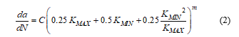
Paris et al. [23] initially suggested that the crack growth rate (da/dN) could be associated with the stress intensity factor range (ΔK) if the material is subjected to variable loading of constant amplitude (1). The material coefficients (C) and (m) are obtained experimentally.
![]() C, m: Paris law constants which depends on the material
C, m: Paris law constants which depends on the material
KMIN: Minimum stress intensity factor (MPa.m0.5)
KMAX: Maximum stress intensity factor (MPa.m0.5)
Several experiments have shown that the length of the crack varies exponentially as a function of the number of cycles [1], [4], [9]. From this, it can be concluded that crack growth is rather slow until the final phase of fatigue life, where a relatively short number of cycles could lead to rapid crack growth resulting in failure. The initial crack length appears to be a very significant parameter for fatigue life assessment.
Numerous crack growth models have been suggested to predict the fatigue life of the structures. These models relate (da/dN) to the amplitude of stress or the maximum stress that can be expressed by the stress intensity factor.
Paris’ Law is the simplest fatigue crack growth equation that gives the rate of fatigue crack growth [23]. A modified form which uses the effective stress to account for the crack closure [24-25] can be written as in (2).
 Crack closure is a fatigue loading phenomenon where, even if an external load is acting on the material, the contact is maintained between the opposite faces of the crack [7]. With an increase in load, a critical value of stress intensity factor (KOP) is achieved when the crack is “open” (Figure 1).
Previous work by the authors [25] outlines the process of calculating the SIF where the correction factors for the analytical model have been introduced (2). These factors are used to enhance the results obtained in the case of high internal pressure and help to take into account the position of the crack (internal or external).
This process will be used in this paper to propose a method for assessing damage caused by a longitudinal semi-elliptical crack present in a metallic pipe. This pipe is considered to be subject to variable amplitude loading (internal pressure) caused by the water hammer phenomenon.
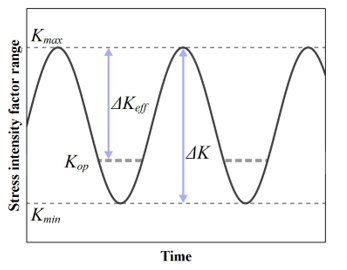 Figure 1: Crack closure effect
3. Damage accumulation model
Fatigue loading of pipeline structures varies by nature. Figure 2 shows a typical operating pressure spectrum for a pipeline. During fatigue loading, the pipeline material undergoes alterations resulting in damage [26]-[28]. It is therefore essential that models explicitly take into account the variability of fatigue loading.
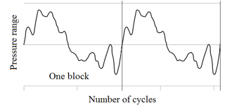 Figure 2: Typical operation pressure spectrum
The models used to describe fatigue-related damage accumulation can currently be classified into two categories: linear and non-linear approaches. Palmgren-Miner rule (3) is a linear damage accumulation approach that is widely used in engineering equipment because of its simplicity [29]. Damage (D) per stress level is estimated to be the ratio of the number of cycles (n) to the estimated lifetime of fatigue (N). Total damage is given by summing all estimated damage values. The summation should be equal to 1 or a given critical value as a failure criterion.
![]() It is well known that the Palmgren-Miner Rule does not take into account the load sequences, load conditions and load interaction effects [30]. Many methods of fatigue damage accumulation have been suggested to fix the downside of this rule, and a large number of these models are based on nonlinear accumulation laws [31]-[33]. Load sequences and interaction effects are, in general, very important issues in the fatigue damage accumulation.
It is well known that the Palmgren-Miner Rule does not take into account the load sequences, load conditions and load interaction effects [30]. Many methods of fatigue damage accumulation have been suggested to fix the downside of this rule, and a large number of these models are based on nonlinear accumulation laws [31]-[33]. Load sequences and interaction effects are, in general, very important issues in the fatigue damage accumulation.
The main purpose of this paper is to propose a nonlinear model for fatigue damage accumulation based on fracture mechanics parameters. In this numerical model, the effect of the load interaction is considered. This damage model is described in equation (4). The stress intensity factor (KI) and the crack depth (a) for a given stress level are estimated using a model developed by authors in [25]. This model allows the calculation of damage induced by a single pressure cycle and is defined as the maximum value between the ratio (a/t) and (KI/KIC), where (t) is the thickness of the pipe wall.
The damage accumulation values vary between a minimum value and 1 (or a specified critical value). The minimum value corresponds to the damage value calculated with the initial crack size. The value 1 signifies the rupture of the pipe.
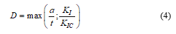 In the case where the value of 1 is caused by the ratio (a/t), it can be concluded that the propagation of the crack induces a leak in the structure. Otherwise, we will conclude that there has been a break (K/KIC ratio equal to 1).
The model (4) alone does not allow to estimate the damage induced by an entire pressure spectrum. This model is intended to be used in an algorithm described in Figure 3. This allows the load interaction effect to be taken into account when the pipe is subjected to static or variable loading.
The algorithm for calculating accumulated damage developed hereby is based on the work of Thun et al. [34]. They estimate the damage accumulation using an analytical model. In this paper, the approach is based on numerical calculation of the damage accumulation and is illustrated in Figure 3. In this Figure, the pressure peak (pi) is applied for (ni) cycles. This algorithm is developed using C language and permits to estimate the damage accumulation after the application of (Nb_Blocks) cycles. Each cycle comprises (k) pressure peaks. The pressure peaks correspond to the sudden variation of the internal pressure in the pipe due to the phenomenon of water hammer.
The first step of the algorithm consist on calculating the damage (D1) due to the first pressure peak (p1) and the corresponding number of cycles (n1) is estimated using the proposed damage model (4). This damage (D1) is used to compute (N2,equ) that induce the same damage but this time using the second pressure peak ((p2) in this case). This step converts the previous damage into equivalent cycles.
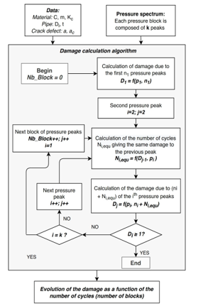 Figure 3: Damage accumulation algorithm
To calculate the damage (D2) after the second pressure peaks (p2) (and the previous ones), the number of cycles (N2) for the second stress level is added to (N2,equ). The damage model (4), taking the dimensions of the crack and the constant amplitude pressure p2 for (n2+N2,equ) cycles as parameters, is used to estimate D2.
The same steps apply for the following pressure peaks until reaching the last peak of the block. As long as the value of the calculated damage does not exceed the critical value (here 1), the algorithm continue by resuming to the first pressure peaks and incrementing the number of cycles by 1 (one block equal to one cycle). The value of the estimated damage takes the previous damages into consideration on the basis of this concept.
It should be noted that, this model takes as input the pressure spectrum due to water hammer. This can be achieved by solving a system of equations that describes the transient flow of fluid in the pipe using the Method of Characteristics (MOC) [14, 17, 18, 25]. A more detailed study is led by authors in [25]. Only the results needed to build the study will be presented in this paper.
4. Water hammer
The water hammer is one of the most significant examples of a transient flow in pressurized pipelines. The history of the study of this phenomenon dates back to the 19th century [35]. The first approaches to mathematical formulation resulted in the most common formula that relates the variation in maximum pressure (Δp) to the change in fluid velocity before and after a sudden valve shift (Δv) [35] as mentioned in (5). Where (ρ) is fluid density, and (c) is wave propagation celerity.
![]() The above method is a useful description of the phenomenon from a practical point of view. In view of its simplicity, equation (5) has made it possible for transient flow cases in elastic pipes, to estimate the maximal pressure range due to the water hammer. This has been seen to be satisfactory for many years. While this formulation is still common, more complex and accurate descriptions of the phenomenon have been developed.
The above method is a useful description of the phenomenon from a practical point of view. In view of its simplicity, equation (5) has made it possible for transient flow cases in elastic pipes, to estimate the maximal pressure range due to the water hammer. This has been seen to be satisfactory for many years. While this formulation is still common, more complex and accurate descriptions of the phenomenon have been developed.
The mathematical description of transient flow in pipelines is expressed by a set of two partial differential equations [14, 25, 35], i.e. the continuity equation (6), the momentum equation (7). It is applicable in the case of elastic pipe and describes the analytical pattern of the water hammer model for compressible fluid flow.
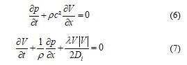 Where:
p: fluid pressure (MPa)
V: Instantaneous fluid velocity (m/s)
t: Time (s)
x: One-dimensional axis (m)
λ: Darcy-Weisbach friction coefficient
Di: Internal pipe diameter (m)
The method of characteristics (MOC), characterized by rapid convergence and high accuracy of estimation outcomes, can be used to easily resolve this partial differential equation system [36-37]. In the computation, the initial conditions used are p0=56.05MPa and V0=1.2m/s. The value of p0 corresponds to the nominal pressure and V0 corresponds to the fluid velocity at the inlet of the pipe.
The obtained curves, using the MOC, describe the pressure variation of the fluid within the pipe as time-based. Fatigue life can only be predicted through the proposed numerical approach using pressure variation against the number of cycles. In an earlier study [37], it is detailed about how to convert time-based pressure spectrum to pressure spectrum according to the number of cycles by applying filters.
In this way, the pressure spectrum caused by the water hammer phenomenon can be estimated when a valve is suddenly closed/opened. Thus, the effect of this dynamic load on crack defects in the metallic pipe is simulated and the time for calculation is greatly optimized.
Three separate fluids are included in this study, their characteristics are shown in Table 1. Figure 4 shows the pipe dimensions. The pipe is made from the material API X52 with a Young modulus of 200GPa and a Poisson ratio of 0.3. As the pressure considered in this study does not exceed the specified minimum yield strength (SMYS), a linear elastic behavior of the material is considered. The friction factor λ is 0.019.
Table 1: Characteristics of the studied fluids [25]
| Fluid | ρ (kg/m3) | C (m/s) |
| Water | 998,2 | 1366,03 |
| Light Oil | 813 | 1463,21 |
| Heavy Oil | 962 | 1105,13 |
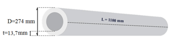 Figure 4: Pipe dimensions
Figure 5 indicates the outcome of that process for the three separate fluids when the valve opens and closes. The pressure drops to 26.85, 26.36 and 25.98 MPa during the sudden closing of the valves for water, light oil and heavy oil respectively.
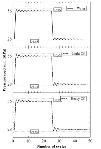 Figure 5: Filtered water hammer pressure waves for three different fluids (One block of pressure spectrum)
The maximum pressures reached are 3.73, 4.34 and 5.14% higher than the nominal pressure (56.05 MPa) of the fluid for water, light oil and heavy oil respectively. The simple equation (5) predicts increases in pressure due to the effect of water hammer of 2.43, 2.12 and 1.89% for water, light oil and heavy oil respectively.
This shows that taking more proper method to estimate pressure variation in case of water hammer when estimating the life of pipes will allow more reliable results. These pressures spectrums represent one block of variable amplitude pressure range. This can be used to assess the effect of water hammer in the case of different fluids on the integrity of the pipe structure.
The method used to calculate the pressure difference induced by water hammer provides results superior to those predicted by (5). Note that (5) does not provide any information on the cycles count until water hammer waves are attenuated. It is therefore important for industrialists to use a more accurate method, taking into account the effect of the water hammer. This is particularly important for the analysis of defects in highly pressurized pipeline structures.
5. Validation study
In order to validate the damage estimation approach proposed in this paper, we will compare the results obtained from our model with those published by Zoran [38, 39]. Pipe and fluids properties will be adapted for this purpose.
The proposed approach will be compared in the case of the two types of loading: constant (Figure 6) and variable (Figure 7) amplitude loading. In both cases, the pipe contains an internal semi-elliptical crack in longitudinal orientation. Initial crack size is 0.4 mm for all cases with a ratio (crack depth / crack width) equal to 0.4. In the case of constant amplitude loading, the evolution of the propagation of the crack is calculated for four internal pressures: 40, 50, 65 and 75MPa. The results are shown in Figure 6. One can see from the Figure 6 that the evolution of the number of cycles as a function of the crack depth obtained from the proposed model follows that of the literature.
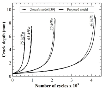 Figure 6: Crack propagation vs. number of cycle in the case of constant amplitude pressure spectrum
In the case of variable amplitude loading, Zoran [39] defined two types of loadings, one heavy and one medium. Five standardized pressure values (20, 35, 45, 60 and 70 MPa) are considered for each type of loading.
In Figure 7, the references EP70, EP60, EP45, EP35, and EP20 are kept the same from that of the literature. For example, in the codification EP70, 70 represents the equivalent pressure range of the pipe [39].
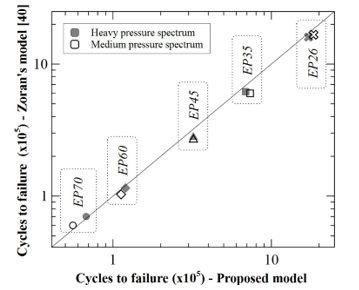 Figure 7: Crack propagation vs. number of cycle in the case of variable amplitude pressure spectrum
As shown in Figures 6 and 7, the deviance between the results obtained from the model developed and those of the literature remain acceptable. Which validated the proposed model.
6. Parametric study
In order to study the effect of the water hammer on the severity of the crack defect in the pipe, 54 cases will be investigated. In all cases, the initial crack depth is the same and equal to 3.25 mm. A semi-elliptical surface crack is the defect being studied.
The proposed algorithm (Figure 3) takes as input the pressure spectrum presented in Figure 5 to simulate a pipe transporting water, light oil and heavy oil. The crack dimensions (a/c) are 0.4, 0.6 and 0.8. The ratio (a/c) corresponds to the ratio crack depth to crack width.
The crack is considered to be located in the base metal, the welding metal and the heat-affected-zone. The parameters of the Paris Law (C and m) along with the critical stress intensity factor used for each zone are shown in Table 2. The process for obtaining the Paris Law and KIC parameters can be found in [40] and [41] respectively. The position of the crack (internal or external) is also being studied.
Table 2: Material properties
| Material | C[40] | m[40] | KIC [41] (MPa.m0.5) |
| Base metal | 3.3 e-09 | 2.74 | 53.36 |
| HAZ | 1.13 e-09 | 3.25 | 53.36 |
| Weld metal | 1.04 e-09 | 3.28 | 61.02 |
7. Results and discussion
Figures 8, 9 and 10, along with Table 3, present the results of the numerical damage estimation model developed and validated hereby. The curves show an exponential evolution of the damage until the rupture or leakage of the structure (when the damage accumulation is equal to unity). This is typical for the propagation of longitudinal cracks in the metal pipe under cyclic pressure.
In order to obtain readable curves, Figure 8 groups together the evolutions of the damage accumulated only for the internal surface cracks present in pipes transporting water. This curve will allow us to evaluate the effect of the crack dimension on the evolution of the damage accumulation. Figure 9 contains the results of the accumulated damage for cracks of dimension (a/c) of 0.4 present in pipes transporting water. This will allow us to evaluate the effect of the crack position (internal or external) on the evolution of the damage. Figure 10 regroups the evolutions of the accumulated damage for the internal surface cracks of dimensions a/c of 0.4. This will allow us to evaluate the effect of the fluid transported by the pipeline on the evolution of the damage of the crack defect. Table 3 presents the number of cycles to fatigue for all of the studied cases.
All the curves start with a damage value of 0.237, which corresponds to the initial crack depth (3.25mm) divided by the thickness of the pipe (13.7mm). This shows that for all the cases studied in this paper and for the first peak of the pressure spectrum, we obtain a value of (a/t) greater than (K/KIC).
In the following, the lower value of the crack dimension is used as a reference for the calculation of the deviations (the results for a/c equal to 0.8 to calculate the deviation for the cracks a/c equal to 0.6 and likewise for a/c equal to 0.6 and 0.4).
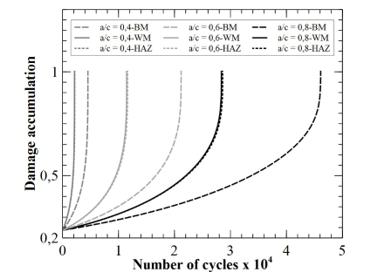 Figure 8: Effect of crack dimensions on the damage accumulation for water and internal cracks
It can be noted from reading the Figure 8 that, for the cracks located in the base material, a drop of -54% in term of fatigue life if crack dimension a / c evolves from 0.8 value to 0.6. From a/c = 0.6 to 0.4, a drop of -78.6% is observed. For the cracks located in the weld material, one notices a drop in fatigue life of -59.7% and -81.5% for respectively the crack with a/c dimension of 0.6 and 0.4. In the case of crack located in the heat affected zone, one notices a fall of -59.4% and -81.3% for respectively the crack with a/c dimension of 0.6 and 0.4. These values of deviations are very close to those observed in the case of a crack located in the welding material.
From these values of deviations, one can clearly see the important effect of the dimension of the crack and more precisely the ratio (a/c) on the fatigue lifetime. In fact, the lower the (a/c) ratio, the more harmful the crack.
From Figure 9, and if we take this time as reference of deviations the values obtained for the internal surface cracks, we observe a difference of + 26.8%, + 31.5% and + 39.4% compared to external surface cracks for defects located in the base material, in the weld material and in the heat-affected area, respectively. This confirms the fact that internal surface cracks are more harmful than external cracks (with same dimensions), regardless of the type of load or the material in which it is located.
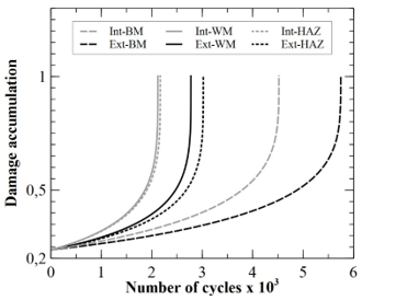 Figure 9: Effect of the position of the crack on the damage accumulation for crack with a/c of 0.4 and water
From a simple reading of Figure 10, we can notice that the evolution of the accumulated damage in the case of a cracked pipe transporting light oil is very close to that obtained for the pipe transporting heavy oil.
Let us take as reference of calculation of the deviations the results obtained in the case of crack present in a pipe transporting water. There is a difference of almost -6.9%, -8.15% and -8.1% in terms of fatigue life between the values obtained for the pipe transporting water and the pipes transporting oil (light or heavy) for cracks located in the base material, the weld material and in the heat-affected area, respectively.
This shows that the transported fluid has an effect on the evolution of the damage and therefore on the propagation of the crack. Admittedly, the effect of the fluid is not as pronounced as the other parameters studied. But if one seeks to obtain a precise evaluation of the damage induced by a defect on the structure, this parameter should not be neglected.
Let us consider the case of an internal crack of dimension (a/c) of 0.4 present in a pipe transporting heavy oil. From Figures 8, 9 and 10 as well as Table 3, the crack defect in the weld material has a deviation of -54.5% in terms of fatigue life compared to a crack in the base material. By taking the same reference, the crack located in the heat affected zone presents a deviation of -53.39%.
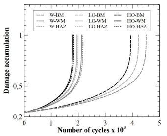 Figure 10: Effect of transported fluid on the damage accumulation for internal crack with dimension of 0.4
It is concluded that the crack is much more harmful when it is located in the weld material or the HAZ than when it is located in the base material. The most harmful crack remains that located in the welding material.
Table 3: Number of cycles to fatigue for all the studied cases
| Number of cycles to fatigue (cycles) | |||||||
| Base Metal | Weld Metal | HAZ | |||||
| a/c | Int. | Ext. | Int. | Ext. | Int. | Ext. | |
| Water | 0,4 | 4531 | 5744 | 2118 | 2785 | 2168 | 3023 |
| 0,6 | 21194 | 28211 | 11447 | 15846 | 11618 | 17009 | |
| 0,8 | 46117 | 64454 | 28382 | 41250 | 28600 | 43965 | |
| Light Oil | 0,4 | 4218 | 5453 | 1944 | 2607 | 1991 | 2831 |
| 0,6 | 18790 | 25506 | 10006 | 14127 | 10161 | 15170 | |
| 0,8 | 38939 | 55498 | 23628 | 35024 | 23822 | 37344 | |
| Heavy Oil | 0,4 | 3931 | 5093 | 1787 | 2409 | 1832 | 2618 |
| 0,6 | 16677 | 22688 | 8760 | 12432 | 8904 | 13360 | |
| 0,8 | 32914 | 47016 | 19701 | 29354 | 19881 | 31322 | |
Int.: Internal cracks. Ext.: External cracks
8. Conclusion
A nonlinear model was proposed to estimate the accumulation of fatigue damage in cracked pipes subjected to water hammer. This model allows for the load sequence to be taken into consideration when the structure is subjected to variable amplitude loading, but can also be used in the case of constant amplitude loading.
The model uses the pressure spectrum calculated using the method of characteristics as input. It is based on an algorithm that allows the load sequence to be taken into account. This algorithm uses a mathematical model of the stress intensity factor that incorporates correction factors. One factor is used to improve the accuracy of the results in the case of high stress, and the other allows the crack location (internal or external) to be taken into account.
After validation of the model against results from the literature, it is used in a parametric study. The objective of this study is to evaluate the effect of certain parameters on the evolution of accumulated damage with the number of fatigue cycles. These parameters are the fluid transported by the pipe (water, light oil and heavy oil), the position (external and internal), the dimension (expressed by the ratio depth of the crack to the width of the defect) and the location of a semi-elliptical crack (base metal, weld metal and heat affected zone). These are the parameters that have the greatest impact on the harmfulness of the crack defect.
On the basis of the results achieved, the significant effect of the crack dimension and, more precisely, the ratio (a/c) on accumulation damage can be clearly seen. In fact, the lower the ratio (a/c), the more harmful the crack is. Internal surface cracks are found to be more harmful than external cracks, regardless of the type of load or material in which they are located. When located in the welding material or in the heat-affected zone, the surface crack is far more harmful than when located in the base material. The most harmful crack is the one in the welding metal.
The effect of the transported fluid is not as pronounced as the other parameters studied, but this parameter should not be neglected if the objective is to obtain a precise assessment of the damage caused by a structural defect.
This model will be used in further studies to analyze the effect of other types of crack defects on the integrity of a pipe structure subjected to a water hammer or even a high internal pressure.
- L. Zahiri, Z. Mighouar, H. Khatib, K. Mansouri, B. Salhi, “Fatigue life analysis of dented pipes subjected to internal pressure” International Review of Mechanical Engineering, 11(8), 587–596, 2017. https://doi.org/10.15866/ireme.v11i8.12089
- M. A. N. Beltrão, E. M. Castrodeza, F. L Bastian, “Fatigue crack propagation in API 5L X-70 pipeline steel longitudinal welded joints under constant and variable amplitudes” Fatigue & Fracture of Engineering Materials & Structures, 34(5), 321–328, 2011. https://doi.org/10.1111/j.1460-2695.2010.01521.x
- K. Pawan, M. Mamookho, S. Srijan, D. Aniket, “Prediction of the Propagation of Fatigue Cracks in Part-Through Cracked Pipes with CASCA and FRANC2D” Transactions of the Indian Institute of Metals, 2020. https://doi.org/10.1007/s12666-020-01886-z
- S. A. Barter, L. Molent, P. White, B. Dixon, “ Recent Australian full-scale F/A-18 fatigue tests” Structural Integrity and Life, 9(2), 89–112, 2009.
- M. Manjgo, A. Sedmak, B. Grujić, “Fracture and fatigue behaviour of NIOMOL 490K welded joint” Structural Integrity and Life, 8(3), 149–158, 2008.
- B. K. C. Yuen, F. Taheri, “Proposed modifications to the Wheeler retardation model for multiple overloading fatigue life prediction” International Journal of Fatigue, 28(12), 1803–1819, 2006. https://doi.org/10.1016/j.ijfatigue.2005.12.007
- K. D. Singh, K. H. Khor, I. Sinclair, “Finite element and analytical modeling of crack closure due to repeated overloads” Acta Materialia, 56(4), 835–851, 2008. https://doi.org/10.1016/j.actamat.2007.10.046
- M. A. Meggiolaro, J. T. P. de Castro, “On the dominant role of crack closure on fatigue crack growth modeling” International Journal of Fatigue, 25(9-11), 843–854, 2003. https://doi.org/10.1016/S0142-1123(03)00132-4
- H. Dirik, T. Yalçinkaya, “Fatigue Crack Growth under Variable Amplitude Loading through XFEM” Procedia Structural Integrity, 2, 3073–3080, 2016. https://doi.org/10.1016/j.prostr.2016.06.384
- K. Kurmoiartseva, P. Trusov, “Multilevel description of damage accumulation in titanium and titanium alloys” in AIP Conference Proceedings, 2053, 030032, 2018. https://doi.org/10.1063/1.5084393
- L. Muys, J. Zhang, N. Micone, W. De Waele, S. Hertelé, “Cycle-by-cycle simulation of variable amplitude fatigue crack propagation” International Journal Sustainable Construction & Design, 8(1), 2017. https://doi.org/10.21825/scad.v8i1.6808
- A. Vojdani, G. Farrahi, “Reliability assessment of cracked pipes subjected to creep-fatigue loading” Theoretical and Applied Fracture Mechanics, 104, 1–12, 2019. https://doi.org/10.1016/j.tafmec.2019.102333
- J. R. Mohanty, B. B. Verma, P. K. Ray, “Prediction of fatigue crack growth and residual life using an exponential model. Part II: mode-I overload induced retardation” International Journal of Fatigue, 31(3), 425–432, 2009. https://doi.org/10.1016/j.ijfatigue.2008.07.018
- A. Kodura, P. Stefanek, K. Weinerowska-Bords, “An Experimental and Numerical Analysis of Water Hammer Phenomenon in Slurries” Journal of Fluids Engineering, 139(12), 1–9, 2017. https://doi.org/10.1115/1.4037678
- C. Cristoffanini, M. Karkare, M. Aceituno, “Transient Simulation of Long Distance Tailings and Concentrate Pipelines for Operation Training” in SME Annual Meeting/Exhibit, Salt Lake City, UT, 210–214, 2014.
- M. Kandil, A. M. Kamal, T. El-Sayed, “Effect pipes material on water hammer” International Journal of Pressure Vessels and Piping, 179, 2019. https://doi.org/10.1016/j.ijpvp.2019.103996
- T. Wang, J. Jiang, G. Lan, “Research on Accumulator for Water Hammer Protection of Long-Distance Slurry Transportation Pipelines” in Sixth International Symposium on Fluid Machinery and Fluid Engineering (ISFMFE), Wuhan, China,1–6, 2014.
- W. Wan, W. Huang, “Water hammer simulation of a series pipe system using the MacCormack time marching scheme” Acta Mechanica, 229, 3143–3160, 2018. https://doi.org/10.1007/s00707-018-2179-2
- T. Vilkys, V. Rudzinskas, O. Prentkovskis, J. Tretjakovas, N. Visniakov, P. Maruschak, “Evaluation of Failure Pressure for Gas Pipelines with Combined Defects” Metals, 8(5), 346, 2018. https://doi.org/10.3390/met8050346
- A. Okab, K. Alkhazraji, A. Gatta, “Influence of Pressure and Thermal Parameters on Stresses Analysis of Pressurized and Cracked Pipes” Oriental Journal of Chemistry, 35(6), 1640–1646, 2019. https://doi.org/10.13005/ojc/350604
- H. F. B. de Oliveira Dias, Failure Assessment on Effects of Pressure Cycle Induced Fatigue on Natural Gas Pipelines, Instituto Superior Técnico, 2014.
- A. A. Griffith, “The Phenomena of Rupture and Flow in Solids” Philosophical Transactions of the Royal Society of London, 221(582–593), 163–198, 1921. https://doi.org/10.1098/rsta.1921.0006
- P. C. Paris, F. A. Erdogan, “Critical Analysis of Crack Propagation Laws” Journal of Basic Engineering, 85(4), 528–533, 1963. https://doi.org/10.1115/1.3656901
- W. Elber, “Fatigue crack closure under cyclic tension” Engineering Fracture Mechanics, 2, 37–45, 1970. https://doi.org/10.1016/0013-7944(70)90028-7
- Z. Mighouar, L. Zahiri, H. Khatib, K. Mansouri, Z. El Majid, “Effect of Water Hammer on Pipes Containing a Crack Defect” International Journal of Mechanical & Mechatronics Engineering, 18(3), 25–31, 2018.
- A. Benin, S. Nazarova, A. Uzdin, “Designing Scenarios of Damage Accumulation” in International Scientific Conference Energy Management of Municipal Facilities and Sustainable Energy Technologies, 600–610, 2019. https://doi.org/10.1007/978-3-030-19868-8_57
- J. M. Torrenti, G. Pijaudier-Cabot, J. M. Reynouard, Mechanical Behaviour of Concrete, John Wiley and Sons, Inc., 185–223, 2013. https://doi.org/10.1002/9781118557587
- A. Belegundu, S. Nayak, J. Loverich, M. Grissom, “Vibration-Based Damage Accumulation Modeling” in 28th Conference on Mechanical Vibration and Noise, Charlotte, North Carolina, USA, 2016. https://doi.org/10.1115/DETC2016-59106
- M. A. Miner, “Cumulative damage in fatigue” Journal of Applied Mechanics, 12(3), 159–164, 1945.
- S. P. Zhu, H. Z. Huang, Z. L. Wang, “Fatigue life estimation considering damaging and strengthening of low amplitude loads under different load sequences using fuzzy sets approach” International Journal of Damage Mechanics, 20(6), 876–899, 2011. https://doi.org/10.1177/1056789510397077
- B. Isojeh, M. El-Zeghayar, F. Vecchio, “Concrete Damage under Fatigue Loading in Uniaxial Compression” ACI Materials Journal, 114, 225–235, 2017. https://doi.org/10.14359/51689477
- H. Gao, H. Huang, S. Zhu, Y. Li, R. Yuan, “A Modified Nonlinear Damage Accumulation Model for Fatigue Life Prediction Considering Load Interaction Effects” The Scientific World Journal, 2014. https://doi.org/10.1155/2014/164378
- S. R. Maitra, K. S. Reddy, L. S. Ramachandra, “Stress Intensity Factor Based Damage Prediction Model for Plain Concrete under Cyclic Loading” Journal of Materials in Civil Engineering, 30(7), 2018. https://doi.org/10.1061/(ASCE)MT.1943-5533.0002289
- H. Thun, U. Ohlsson, L. Elfgren, “A deformation Criterion for Fatigue of Concrete in Tension” Structural Concrete, 12(3), 187–197, 2011. https://doi.org/10.1002/suco.201100013
- B. E. Wylie, V. L. Streeter, L. Suo, Fluid Transients in Systems, Englewood Hills, Prentice Hall, NJ, 1993.
- M. Dallali, M.A. Guidara, M.A. Bouaziz, C. Schmitt, E. Haj-Taieb, Z. Azari, “Accuracy and security analysis of transient flows in relatively long pipelines” Engineering Failure Analysis, 51, 69–82, 2015. https://doi.org/10.1016/j.engfailanal.2015.03.001
- Z. Mighouar, L. Zahiri, H. Khatib, K. Mansouri, “Numerical Modeling Of Water Hammer Pressure Waves In Steel Pipes” in 1st International Conference on Innovative Research in Applied Science, Engineering and Technology (IRASET), Meknes, Morocco, 2020. https://doi.org/10.1109/IRASET48871.2020.9092171
- D. P. Zoran, “Fatigue Crack Growth Prediction For Pipes With Known Initial Crack” Trends in the Development of Machinery and Associated Technology, 461–464, 2013.
- D. P. Zoran, “Assessment Of Fatigue Crack Growth In Pipes Subjected To Variable Loading” Trends in the Development of Machinery and Associated Technology, 109–112, 2014.
- L. Zahiri, Z. Mighouar, H. Khatib, K. Mansouri, B. Salhi, “Fatigue Behavior Of Longitudinal Welded Pipes Subjected To Cyclic Internal Pressure, Containing Welding Defects” International Journal of Mechanical Engineering & Technology, 9(3), 560–569, 2018.
- A. Belalia, A Rahmani, G. B. Lenkey, G. Pluvinage, Z. Azari, “Dynamic characterization of API 5L X52 pipeline steel” Key Engineering Materials, 498, 15–30, 2012. https://doi.org/10.4028/www.scientific.net/KEM.498.15