Remote Control of Garden Plantation Water Pumps using Arduino and GSM Mobile

Adv. Sci. Technol. Eng. Syst. J. 5(4), 499–504 (2020);
 DOI: 10.25046/aj050459
A remotely mobile phone controlled electronic system for supplying water to garden plantations in a greenhouse or similar environment was designed and experimentally implemented. The system monitors the garden environmental conditions such as soil moisture, temperature, humidity and sunlight and a remote user can send commands from his mobile phone such as to switch ON/OFF water pumps, supply water for the plants for certain duration and acquire the environmental status information of the plantation. The water pumps are controlled by the Arduino microcontroller that is the core part of the electronic system. The user has the ability to monitor the environmental conditions on his mobile phone. Such systems can facilitate monitoring, give flexibility of controlling, save time and human labour and increase productivity as a result of automation and remote controlling.
1. Introduction
In the agricultural sector, the traditional irrigation techniques like watering cans, drip and sprinkler irrigations require farmers to be physically present in their farm lands to regularly supply water to their crops, which is a manually controlled irrigation method that results in wastage of human power as well as time. To circumvent labour presence at the farm site, in [1] Dual Tone Multi-Frequency (DTMF) based remotely controlled electronic system was proposed to control the switching states of agricultural water pumps located in remote farm areas. On the other hand, nowadays water shortage is becoming one of the biggest problems in the world from domestic home use as well as in agricultural and industrial sectors. Many different methods are developed for conservation of water. As water is one of the scarce natural resources, it is important to properly use and manage our usage in different sectors and hence there is a need to design systems that are used to monitor and control our water usage including in homes, agriculture and industrial sectors [2], [3]. It is known that agriculture is one of the fields where water is required in tremendous quantity and there are many techniques to save or to control wastage of water from agriculture. With the development of technology in water saving irrigation and automation, automatic irrigation is going to be more popular in the farms. In [4] an automatic control system is designed and implemented for garden plantations based on soil moisture, temperature and light sensors. The system monitors and controls the soil moisture, temperature and light intensity based on the three sensors and the Arduino module that automatically controls a water pump, a fan and a lighting fixture based on the sensor information in the greenhouse. It controls the water pump automatically by the Arduino and the built electronic system.
Automation of irrigation systems based on soil moisture sensors (SMS) was also implemented in [5] to optimize water usage efficiency by maintaining soil moisture at optimum levels. It was found that a significant percentage of water savings can be achieved based on the quality of the installed sensors in the farm land. An Automatic irrigation system based on Arduino microcontroller and a sensor sensing the dampness of the soil was also proposed in [6]. An Arduino based automated irrigation system based on soil moisture sensor was also proposed in [7]. In this system, the microcontroller is interfaced with the HC-05 Bluetooth module that can be connected to Android phone for controlling the water pumps in the farm. The drawback of this control is the limited range of the Bluetooth communication that can be from a distance of 10 m to 100 m from the transmitter [8]. In plant watering system that was proposed in [9], the soil moisture sensor checks the moisture level in the soil and if moisture level is low then the Arduino informs the user by sending message to the user cell phone then the user sends a command that switches on the water pump to provide water to the plants. However, this system is based on a PIC16F628 microcontroller that is different from Arduino and used two metal plate sensors for moisture sensing instead of standard commercially available sensors that limits the accuracy. A microcontroller based irrigation system was also proposed in [10] based on 8051 Microcontroller. However, a system based on Arduino simplifies the process of working with microcontrollers and it is inexpensive and widely used everywhere in recent days [11], [12].
The purpose of the work in this paper is to further improve the work done in [4] so that there is an ability to remotely control the water pumps depending on the farm environmental conditions received from the Arduino. The designed electronic system monitors the soil water level (moisture level) of the garden plantation and supplies water through the water pumps that are controlled by the Arduino microcontroller. The system is to be controlled by sending commands remotely from a mobile phone of the owner of the garden plantation or the farms. In addition, the system also needs to monitor the garden environmental conditions (moisture, temperature, light, humidity) and inform the user so that he can take the necessary actions. Such Global System for Mobile (GSM) based automatic irrigation system increases the productivity of farms and eliminates the cost of human labour used in manual irrigation methods. It provides convenience in accessing the system from anywhere at any time.
2. Methods and Materials
The designed system and the various components and standards used for this project are described in this section
2.1. System Design and Components
The designed system as shown in Figure 1 is implemented to provide the necessary supplies for a farm or a greenhouse. The system is designed to monitor and control the sensor elements through the Arduino microcontroller and providing the status of the land to the user through the GSM module. The sensors are connected to the Arduino to provide the microcontroller with the soil moisture, humidity and temperature and light status of the plantation. The microcontroller stores the sensors data information and then sends them to the user upon request. It also receives commands from the user through the GSM module and then supplies the land with water, light and air conditioning by switching ON/OFF the water pumps, the light and the fans respectively depending on the required needs of the plants.
The standards of the project are commercially available components brought together to form the project and make it a complete one. The design aspect is to integrate all the design components in a way to achieve our target and the target tasks are achieved through programming the Arduino microcontroller that is interacting with the various input and output components. Some of the main components of the system are listed below.
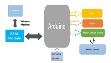 Figure 1: System Block Diagram
2.1.1. Arduino Uno
Arduino is an open source microcontroller used for hardware and software integration. Arduino can be interfaced with sensor elements and control them in the real world. Arduino has a set of digital and analogue input/output pins that can be interfaced to distinctive developed boards (shields) and different sensor circuits [12]. Serial communication interfaces including Universal Serial Bus (USB) are required for loading programs from Personal Computer (PC) to the Arduino. The Arduino board as shown in Figure 2 provides an integrated development environment (IDE) for programming the microcontroller to process various types of projects. The Arduino IDE provides a simplified integrated platform which can run on regular PCs and allows users to write programs for Arduino using C or C++ language.
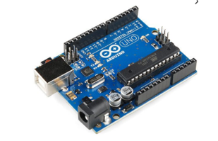 Figure 2: Arduino UNO Board
2.1.2. GSM GPRS Quad Band Board SIM900 Shield for Arduino
GSM is a second generation (2G) digital cellular networks used by mobile phones. A GSM modem is a device that modulates and demodulates signals for communications. The modem used in this project is SIMCOM SIM900 [13], which is s a quad-band GSM/General Packet Radio Service (GPRS) modem as it can operate at four frequencies (850 MHz, 900 MHz, 1800 MHz and 1900 MHz). GSM provides a wide range of things to remotely control from anywhere with your fingertips. SIM900 GSM module can be used to send and receive SMS by connecting it to a PC or Arduino when a Subscriber Identification Module (SIM) card is inserted. The GSM modem can send ATtention (AT) commands to send or receive Short Message Service (SMS) from PC via a COM (serial or USB) port. The SIM900 GSM module used in this project as shown in Figure 3 consists of a Transistor-Transistor Logic (TTL) and an RS232 interface. The TTL interface allows you to interface directly with a microcontroller while the RS232 interface allows to communication with PC.
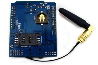 Figure 3: GSM/GPRS Quad Band Board
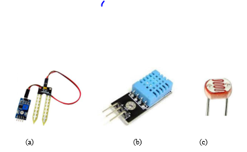 Figure 4: Plant Environmental Condition Sensors: (a) Soil moisture sensor, (b) The Arduino DHT11, (c) LDR
2.1.3. Plant Environmental Condition Sensors
The proposed system is intended to control and monitor four different parameters (soil moisture, temperature, humidity and light status) of a certain garden or greenhouse planation that are vital for the healthy growth of plants. Calculating the soil moisture using soil moisture sensors in the fields is important to help the farmers improve irrigation system efficiently. The quality of the crop production can be increased by management of soil moisture during critical stages of plant growth. Volumetric water content is calculated indirectly by soil moisture sensor using different parameters of the soil like dielectric constant, electrical resistance and neutrons interaction. Controlling and monitoring of the temperature around the plants is essential for maintaining their healthy growth. The system turns on the fans for cooling the plants if the temperature and/or humidity increases above a certain preset value. The threshold (preset) temperature and/or humidity is chosen depending on the requirements of the plants so that they are not affected by any excess heat which may affect their metabolism and healthy growth. Similarly, the system has a light sensor that detects the level of lighting in the plant surroundings. The sensor is a light dependent resistor (LDR) used for in light/dark sensor circuits. Normally, the resistance of an LDR is very high, can be in the order of Mega ohms (MW), but when it is illuminated with light, its resistance drops dramatically allowing more current to pass through it. Figure 4 shows the soil moisture sensor, the temperature/ humidity composite sensor (DHT11 sensor) and the LDR light sensor components used for this project. The system is flexible in that the preset moisture level, temperature, humidity or light levels could be modified if needed by the user depending on the requirements. By changing the Arduino code, any desired level could be programmed by the user.
2.1.4. Arduino Compatible L298N Stepper Motor Driver
This 2x2A DC Motor drive for Arduino allows driving two channel DC motors. It uses a L298N chip, which deliveries output current up to 2A for each channel. The speed control is achieved through conventional Pulse Width Modulation (PWM) which can be obtained from Arduino’s PWM output Pin 5 and 6. The enable/disable function of the motor control is signaled by Arduino Digital Pins 4 and 7. The Motor shield can be powered directly from Arduino or from external power source. It is strongly encouraged to use external power supply to power the motor shield. The Arduino Motor Shield as shown in Figure 5 is based on the L298, which is a dual full-bridge driver designed to drive inductive loads such as relays, solenoids, DC and stepping motors. In this project, this component is being used because it lets to drive the water pump motors connected to the Arduino board to control the speed and direction of each one independently.
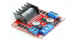 Figure 5: Arduino Compatible L298N motor drivers
2.2. Complete overall circuit
The system contains the following components: the microcontroller which is the Arduino Uno, GSM Module, the temperature and humidity sensor which is the DHT11, soil moisture sensors, a L298N motor driver, a 5V relay, water pumps, fans, LEDs, light sensor and rechargeable batteries as shown in the overall circuit in Figure 6. The micro controller used is the Arduino Uno based on Atmega328P, it has 14 electronic input/output pins, powered by a battery and connected to the GSM Module, sensors and hardware devices compatible with each sensors. All the components are tightly fixed on a wooden base and surrounded with wood and partly glass from the sides to allow light in the day time so that the plants get the amount of light it needs in the day time as seen in the prototype in [4]. When it is dark the LDR will give the readings to the Arduino Uno then the Arduino sends this information to the user through the GSM Module. Then the user will send back a message to the GSM that turns ON the lights. There are also four holes on the surrounding wood to fix the four fans. The fans will work when the user finds that the plants need cooling depending on the environmental conditions.
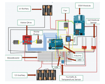 Figure 6: Complete Circuit Connections
3. Software Implementation
The Arduino Uno was programmed for preset values of moisture, temperature, humidity and light environmental conditions that can be simply changed in the program (Arduino software). For the testing purposes, when temperature is equal to or above 27 degrees and the humidity is above 70 %, the user will send a command message to turn on the fans and will stop it, if temperature is less than 27 degrees and the humidity is less than 70 %. These temperature and humidity threshold values can be easily changed in the Arduino code as per the user’s interest. The DH11 composite humidity-temperature sensor will be responsible to give the reading to the system. The water pumps work with the user’s permission. The speed of the water pump that supplies water to the land depends on the moisture level of the land. For the experiment, the moisture levels are divided into four levels that are high (65 % ≤ moisture level ≤ 100 %), medium (50 % ≤ moisture level < 65 %), medium-low (25 % ≤ moisture level < 50 %) and very low (0 % ≤ moisture level < 25 %). This threshold values can be easily changed in the program. When the soil moisture is high the water pump is OFF. When the soil moisture is medium the speed of the water pump is medium. When the soil moisture is medium-low the water pump is in medium-low speed. However, when the soil moisture is very low the water pump speed is high so that it pumps high quantity of water to the plants.
For simplicity, we call the text message sent by the user to be “switching states”. This switching states provide information about the status of the two motor pumps, the lighting bulb (LED for the experiment) and the fan status. The set of the switching states consists of MOTOR1ON, MOTOR1OFF, MOTOR2ON, MOTOR2OFF, FANON, FANOFF, LIGHTON and LIGHTOFF. The user sends one of the mentioned switching states to turn ON/OFF, the motor pumps, the fan or the light in the farm. The other text message sent by the user is the STATUS message to get the environmental condition (moisture level, temperature, humidity and lighting conditions) of the farm or the greenhouse so that the user is aware of the status on the site and then sends the necessary commands to control the water pumps, the light and the fans accordingly. The overall working of the program that is uploaded to the Arduino can be described in a flow-chart as shown in Figure 7.
After declaration of the variables and initializations, in the main program loop, the Arduino checks if the message is sent from a specific user before executing the SMS command from the sender. This will make the system secure so that only a specific user can control the system.
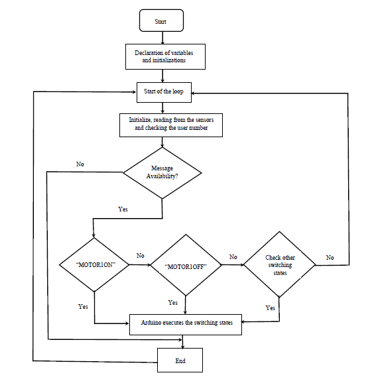 Figure 7: Flow chart of the Arduino program
A sample of the Arduino program (Algorithm 1) to switch on the motor for water pump 1 with high speed is given below. As per the implemented Arduino code, a moisture level between 0% and 25% is considered relatively dry and thus the water pump will run at high speed. A similar code is constructed to check the other three different moisture levels and the water pump will run with a speed corresponding to the proper range.
| Algorithm 1: Arduino code to switch on the motor for water pump 1. |
| output_value1 = map(output_value1,1023,0,0,100); // Get the reading value of moisture sensor 1 and map the value in the range [0 100] where 100 means the maximum wet condition
if(SIM900.find(“+971xxxxxxxxx”)>=0){ // Check whether the message is sent from a specific mobile user if(SIM900.available()>0) // Display any text that the GSM shield sends out to the serial monitor { textMessage = SIM900.readString(); //Get the character from the cellular serial port Serial.print(textMessage); //Print the incoming character to the terminal if(textMessage.indexOf(“MOTOR1ON”)>=0){ // Turn on motor 1 and save current state if(output_value1<25) //if the moisture level is less than 25%, run the water pump at high speed { digitalWrite(in1, LOW); digitalWrite(in2, HIGH); analogWrite(enA, 255); message = “Motor 1 is at high speed”; } } sendmsg(message); // send the message “ Motor 1 is at high speed” to the user }} |
The message “Motor 1 is at high speed” will be sent to the farmer or the user to let him/her know that the water pump is switched on and it is running at high speed due to very low moisture level and the high need of water for the plants. The sample of the Arduino code (Algorithm 2) for this subroutine for sending the message is given below.
| Algorithm 2: Arduino code for sending message to the user confirming that Motor 1 is at high speed. |
| void sendmsg(String message)
{ SIM900.println(“AT+CMGF=1”); //Set the GSM Module in Text Mode delay(100); SIM900.println(“AT+CMGS=\”+971xxxxxxxxx\””); // The farmer or user mobile number to whom the message to be sent delay(100); SIM900.println(message); // The SMS text to be sent to the user delay(100); SIM900.println((char)26); // ASCII code of CTRL+Z delay(100); SIM900.println(); delay(1000); } |
In a similar way, the subroutines corresponding to the rest of the switching states (MOTOR1OFF, MOTOR2ON, MOTOR2OFF, FANON, FANOFF, LIGHTON and LIGHTOFF) SMS command messages are incorporated in the overall program. The corresponding confirmation that provides switching status information (ON or OFF) will also be sent to the farmer or the user regarding the status of the water pumps, the fan and the light bulb. The user has also the option to obtain the environmental condition of the farm or the green house by sending the command “STATUS”. When the Arduino gets this message through the GSM module, the microcontroller collects all the sensors information (light intensity, temperature, humidity and moisture levels in the two sensors) and sends this information as environmental STATUS to the user. The sample of the Arduino code (Algorithm 3) for this subroutine is given below.
| Algorithm 3: Arduino code used for sending STATUS information to the user. |
| Void sendSMS(){ // AT command to set SIM900 to SMS mode
SIM900.println(“AT+CMGF=1”); //Set the GSM Module in Text Mode delay(100); SIM900.println(“AT+CMGS=\”+971xxxxxxxxx\””); //The user mobile number that gets the STATUS information delay(100); SIM900.print(“Light intensity = “); // Send the SMS SIM900.print(val); SIM900.println(“%”); delay(100); SIM900.print(“Temperature = “); SIM900.println(t); delay(100); SIM900.print(“Humidity = “); SIM900.println(h); delay(100); SIM900.print(“Moisture sensor 1 : “); SIM900.print(output_value1); SIM900.println(“%”); delay(100); SIM900.print(“Moisture sensor 2 : “); SIM900.print(output_value2); SIM900.println(“%”); delay(100); SIM900.println((char)26); // ASCII code of CTRL+Z delay(100); SIM900.println(); // Give module time to send SMS delay(1000); } |
4. Experimental Test, Results & Discussions
As discussed in the above sections, an automatic Arduino and GSM based control system for garden plantations or a greenhouse was designed, built and tested in the laboratory and it was found that the system works properly. Figure 8 shows a screenshot sample results of communication between the mobile user and the designed Arduino based system to show how remote controlling is achieved. As shown Figure 8 (a), the owner of the greenhouse sent the message “STATUS” to the system and the owner received the whole status of the greenhouse. This message is helpful because it lets the owner to decide what has to be switched ON or OFF. There are two moisture sensors in this project. Since the moisture sensor 2 has a 0 % moisture, the owner of the green house has decided to switch ON Motor 2. As a result, Motor 2 pumps the water at high speed since the soil level of sensor 2 is 0 %. Similarly, this goes for soil moisture sensor 1. Since the soil moisture level is at 61%, Motor 1 pumps the water at low speed depending on the level of the soil. Depending on the status received, the user can turn ON or OFF the lights, the fans when needed as shown in Figure 8 (b).
- Getting the STATUS information and controlling the water pumps.
- Controlling the LIGHT and the FAN in the green house
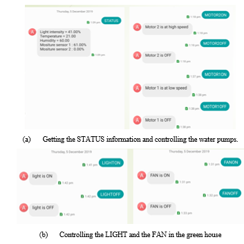 Figure 8. Sample communication between the mobile user and the designed Arduino & GSM based system
5. Conclusions
An Arduino and GSM based electronic system was designed and implemented for monitoring and controlling the level of soil water, temperature, humidity and light intensity for the plants in a garden plantations or greenhouse system. These environmental factors affect the proper and healthy growth of plants. The system is designed and implemented with the Arduino being the core microcontroller interfaced with the GSM module and the sensors providing input information to the Arduino. The system was tested in Laboratory and found working properly. The system can be easily implemented with low-cost budget to make it affordable for everyone as Arduino is a cheap microcontroller with open source software availability. This system can be integrated in the agricultural sector as GSM based irrigation system since mobile phone devices are nowadays used almost everywhere in the world. It can help the farmers to easily remotely control the site and thus save human labour by eliminating the physical presence of persons on the agricultural site. Moreover, it is beneficial to properly manage, conserve water and get increased productivity in agriculture and in the end adding value to the economic growth of a country. By implementing this system not only agricultural farms but also parks, gardens, golf courses can be irrigated. The system benefits the environment positively as it saves water the scare natural resource available for human kind.
Acknowledgment
The authors appreciate the support for the research provided by the American University of Ras Al Khaimah (AURAK).
- B.N. Getu et al., “Remote Controlling of an Agricultural Pump System Based on the Dual Tone Multi-Frequency (DTMF) Technique,” Journal of Engineering Science and Technology, 10 (10), 1261 – 1274, 2015.
http://jestec.taylors.edu.my/Vol%2010%20Issue%2010%20October%202015/Volume%20(10)%20Issue%20(10)%201261-1274.pdf. - B.N. Getu et al., “Automatic water level sensor and controller system” International Conference on Electronic Devices Systems and Applications (ICEDSA), 1-4, 2016. DOI: 10.1109/ICEDSA.2016.7818550.
- B.N. Getu et al., “Automatic Control of Agricultural Pumps Based on Soil Moisture Sensing. Proceedings of the IEEE AFRICON 2015 Conference, 667-671, 2015. DOI: 10.1109/AFRCON.2015.7332052.
- B.N. Getu et al., “Design of Automatic Control System for Garden Plantations Based on Soil Moisture, Temperature and Light Sensing” Journal of Engineering and Applied Sciences, 12 (18), 4782-4786, 2017. DOI: 10.36478/jeasci.2017.4782.4786.
- B.C. Lailhacar, M.D. Dukes, G.L. Miller, “Sensor-Based Control of Irrigation in Bermuda grass” ASAE Annual International Meeting, Tampa, Florida, 1-14, 2005. https://abe.ufl.edu/faculty/mdukes/pdf/publications/SMS/ASAE_05-2180.pdf.
- M. Nagarajapandian, “Automatic Irrigation System On Sensing Soil Moisture Content” International Journal of innovative research in electrical, electronics, instrumentation and control engineering, 3(1), 96-98, 2015. DOI 10.17148/IJIREEICE.2015.3120.
- S. Rakshak, R.W. Deshpande, “Automated Irrigation System Based on Arduino Controller Using Sensors” International Journal of Innovative Research in Computer and Communication Engineering, 5 (7), 13394-13400, 2017. DOI: 10.15680/IJIRCCE.2017. 0507084.
- K.V.S. Sairam, N. Gunasekaran S.R. Redd, “Bluetooth in wireless communication” IEEE Communications Magazine, 40 (6), 90-96, 2002. DOI: 10.1109/MCOM.2002.1007414.
- J. Uddin et al., “Automated Irrigation System Using Solar Power”. 7th International conference on electrical and computer engineering, 228-231, 2012. DOI: 10.1109/ICECE.2012.6471527.
- M. Ojha et al. “Microcontroller Based Plant Irrigation” International Journal of Advanced Technology in Engineering and Science, 3 (10), 71-79, 2015. http://ijates.com/images/short_pdf/1446208511_P71-79.pdf.
- L. Louis, “Working Principle of Arduino and using it as a tool for Study and Research” International Journal of Control, Automation, Communication and Systems (IJCACS), 1(2), 21-29, 2016. DOI: 10.5121/ijcacs.2016.1203
- Arduino Board, 2019: https://www.arduino.cc/en/main/arduinoBoardUno.
- SIM900, 2019. https://simcom.ee/modules/gsm-gprs/sim900/.