Smart Transmission Line Maintenance and Inspection using Mobile Robots
 , Surat Kwanmuang 2, Paisarn Muneesawang 3, Jatuporn Promjan 1, Kanyuta Poochinapan 4, 5
Adv. Sci. Technol. Eng. Syst. J. 5(3), 493–500 (2020);
 DOI: 10.25046/aj050361
The paper presents sharing several of experiences and practices on smart robotic application for overhead transmission line maintenance and inspection. First, the pilot-line pulling robot is an invention used to pull a pilot line which is an important step for additional high voltage conductor installation. The puller robot can traverse the overhead ground wire, OHGW, and pulls a lead line via a set of cradle blocks at intervals, carrying the line above the ground. The robotic puller passes over barriers below the power line, such as the road with traffic, power distribution lines, river, or vegetation making tasks achieved conveniently, safely, and rapidly without impact on nearby communities. The robot was further utilized to pull a lead line/conductor crossing over the electrical substation without interrupting energy and pull a lead line for the improvement of transmission line ground clearances. The developed pilot-line pulling robot has been accredited as the corporate best practice; the standards for innovation, operation, and maintenance are archived for works at all EGAT transmission line operation & maintenance units nationally. Moreover, EGAT was now jointly investigating with universities on a new robotic device for aerial transmission line inspection. The target of the research is to create a mobile robot prototype for inspection of overhead power lines. The inspection robot shall crawl along the ground wire and transpose autonomously across installed equipment on the ground wire, such as vibration dampers, suspension clamps, compression dead ends, etc. In addition, the inspection robot is able to take photos and videos during a transmission line inspection in both offline and online features. Using the robot, transmission line inspection’s labor cost can be reduced, and the new method helps improve patrol and inspection efficiency, comparing to the conventional manpower method. Trough utilization of the new maintenance and inspection robots, utilities can minimize transmission line operation & maintenance budget.
1. Introduction
Electricity Generating Authority of Thailand (EGAT) is Thailand’s leading state enterprise about electric energy under the supervision of the department of energy that has its main business in generation, transmission, and energy sales to other power distribution utilities. In order to promote the development of the national economic and industrial field in conjunction with the “Power for Thai Happiness” corporate agenda, the electricity utility’s mission is to preserve the efficiency of the transmission network for the entire country. In the view of electrical providers, the primary purpose of high voltage transmission systems is the provision of services. EGAT also has a long tradition of developments in the service and management of the energy supply sector utilizing the robotic technology, as demonstrated in Figure 1. Northern Region Operation Division developted an Optical Ground Wire (OPGW) inspection with the robot for examining a damage spot on OPGW’s strands in 2008 [1]. The OPGW inspection robot was upgraded to a better version, 2 years later, such that phase conductors can be inspected also. In 2014, Electrical Maintenance Division and a domestic university co- invented a robot prototype used to inspect boiler water-wall tubes [2]. Utilizing magnetic adhesion, the NDT inspection robot can examine the thickness and the external properties of boiler water-wall tubes. Furthermore, Electrical Maintenance Division funded the national technology center on the same year a project on a tiny robot prototype with 2-cm size or less for internal generator examination [3]. Similar to other robots on the same sector, owing to their smaller form, the robot may analyze inside the generator a distance of less than 3.5 cm. This saves generator testing period and expensive oversea testing robots. In addition, EGAT funded the national metal and materials technology center an R&D work in 2013 about a robotic system development for welding [4]. Main findings include a welding device with applications for welding process monitoring and torch motion creation for overlay welding of parts used in power plants. Afterwards, in 2017, another development for robotic welding system to be used in the repair phase for high-value power plant components was performed [5]. Recently developed [6], new transmission line maintenance and inspection robots are proposed in this paper.
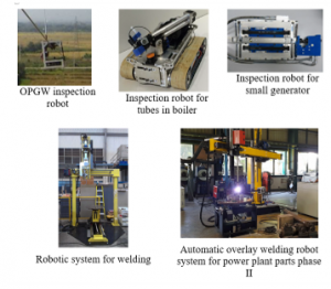
Figure 1: Examples of EGAT innovation on robots [1-5]
A summarized literature review is performed on transmission line maintenance and inspection robotics developed by many researchers. LineScout is a mobile robot developed by the Hydro-Quebec Research Institute to perform live line inspection and maintenance [7-15]. Expliner is an inspection robot developed by the HiBot Corporation, Kansai Electric Power Corporation, and Tokyo Institute of Technology for commercialization [16-17]. Also, TI is an inspection robot developed, evaluated, and demonstrated by Electric Power Research Institute under EHV condition [18]. Moreover, various robot prototypes focusing on 220-500 kV transmission lines are developed by Chinese academy of sciences and many Chinese universities [19-22]. Three types of high voltage transmission line robots are developed by Wuhan University for single and bundled conductors [23-30].
According to presented relevant works, many robots were designed with some limitations for actual field working, e.g. their weight and dimension, specific configuration of conductors, limitation for some tower junction, difficulty for actual field works, and etc. Therefore, two transmission line maintenance and inspection robots with light weight, small size, and ease of use are designed and developed in order to be a new realistic solution for power utilities expecting more efficient O&M system.
The paper sections are arranged as the following. We present in section 2 a developed transmission line maintenance robot. We firstly summarizes problems and constraints of the existing pilot-line pulling method for additional stringing of conductor projects. Then, the development of the new maintenance robot and actual success implementations in transmission lines are presented. The next part, section 3, deals with a novel inspection robot for transmission lines. The background, design, Lab test, and field test of the inspection robot are presented. Working results of both developed robots are discussed in the next section. Evaluation and future improvement are finally concluded in section 5.
2. Transmission Line Maintenance Robot
According to the corporate social responsibility policy, transmission system division desires to improve a better approach for stringing additional power lines while communities suffer no public impacts. Thus, the team of inventors decides to evolve a research project on an advanced approach of pilot-line pulling for the power line installation that conventionally requires manpower and land/water vehicles to pull out a pilot line dragged over the field beneath the power line above, shown as Figure 2-3. The consequence is that it damages farmlands beneath the power line and causes an effect on communities, Figure 3.
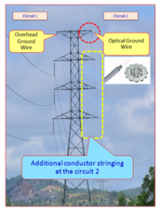
Figure 2: Conductor stringing for the circuit no. 2 to be executed on the blank crossarms of towers
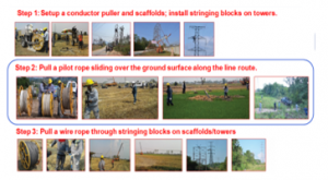
Figure 3: Conventional steps for pilot-line pulling
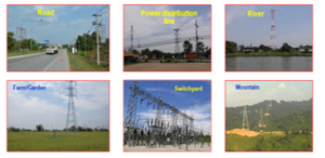
Figure 4: Constraints and challenges on pilot-line pulling
Constraints and challenges for pulling the pilot line with the existing working approach are concluded as the following:
- Interrupted traffic and vegetation damages to landowner (damage compensation to be paid)
- A great amount of workers needed co-working on different places
- Risks of injury by incidents during line pulling operations over the roads, railways, communication lines, power distribution lines, and etc.
- Scaffolds needed above the street and electric distribution line
- Electricity de-energization required when crossing over high voltage switchyards
Therefore, the researchers utilize the robotic technology to diagnose and evolve the new creative approach for better pilot-line pulling operation above all obstructions with the robot developed as a tool to pull out a pilot line through a number of cradle blocks. The complete description of the specially designed puller robot together with a series of cradle blocks is shown in Figure 5. Whilst pulling, the running line is carried on the OHGW at structures and lifts at the height more than 13 m. over the ground, in Figure 6. Thereby, communities suffer no more problems from our jobs, and damage compensation for properties does not need to be paid anymore. Moreover, construction workers can work on stringing a lead line above the highway, river, and live power line with safety, efficiency, and reliability. Additionally, the robot has been utilized further for a lead-line pulling over the live substation in the absence of service outage and also a lead-line pulling for the ground-clearance upgrading of an overhead power line.
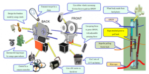
Figure 5: The composition of robot for line pulling work
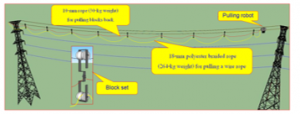
Figure 6: The complete description of the new pilot-line pulling method
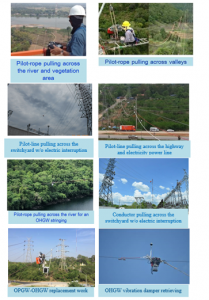
Figure 7: Actual implementations of the transmission line maintenance robot
With success implementation, EGAT has innovated a special robot for pilot-line pulling over all obstructions, and it passed the pulling-force test with 60-kilogram load and 35-degree inclination. The consequences have proved the accomplishment.
3. Transmission Line Inspection Robot
3.1. Background
Throughout the world, inspection of transmission lines usually consumes workforces to achieve the routine tasks by ground patrolling along the transmission line paths. Minimization of man-hour is necessary in order to improve capability while the precision of data is still needed to be conserved. For this reason, partially/completely utilizing robotic technology into the standard line- inspection working method is of great essential. Existing means of routine power line inspection in the past have been dealing with both helicopters and UAVs to minimize cost of manpower. However, the former demands costly capital and operation budget whilst the latter suffers with many constraints, such as short battery lifetime, relevant laws, dependability in operation, and so forth. Therefore, application of an innovative inspection robot rolling along an OHGW can play a significant role in smart transmission line inspection improvement for electric utilities.
The maintenance robot in the earlier section that travels along an OHGW can be practically upgraded to an inspection robot. Nevertheless, the service robot is unable to cross through sequences of obstacles, e.g. vibration dampers, suspension clamps, compression dead ends, and other hardware. That is, the robot has ability to travel just one single span between towers only. To significantly improve inspection efficiency, a new autonomous robot negotiating and crossing successive obstacles automatically must be developed.
Crossing through each tower top is the key challenge for the robotic transmission line inspection. When the robot encounters a tower, personnel needs to climb to each tower and then manually transpose the robot to another side of span. It will be very much more efficient to use if the inspection robot can automatically navigate through tower tops. Nevertheless, autonomous crossing of obstacles repetitively requires huge efforts on advanced technology because equipment installed on the transmission structures have a lot of variety. Regarding mentioned constraints, the research team has designed an approach by developing a new mobile robot which can travel through a series of obstacles and earth wire crossarms with automatic navigation as well as feature of gathering high-quality visual information, e.g., damaged equipment and right-of-way vegetation data [31].
The aim of this research project is to create a novel transmission line section robot that can roll along an OHGW with autonomous crossing of obstacles. This working approach improves more efficiency than the existing approaches, such as ground patrols or helicopters. Photo and VDO via both offline and online (real time) modes can be recorded by the robot; it is a new mean to improve more accurate inspection than the conventional mean. In addition, for an outage event, the robot can be sent out quickly to search for an outage cause in mountainous regions, minimizing the customer’s service interruption.
3.2. Conceptual design of transmission line inspection robot
We designed an overhead power line inspection robot to work with autonomous feature and use a communication network for teleoperation. Figure 8 presents the conceptual design of the inspection robot. One can observe that the control portion is divided into 3 key portions systematically connected inside: moving control, communication control, and remote control parts. Those three units link altogether operations for the entire system and link with operators through an App on a handheld equipment in the field that will track data of the robot transmitted via the cloud network system, which is illustrated in Figure 8.
- Robot motion-control part
Robot movement is controlled by a microprocessor inside, which is the core duty for moving towards a desired location precisely. The inner subsystem includes a system of battery power supply which will energize power to all parts and a feedback-control part that can work with a communication-control part closely for sensing the state of the robot such that the microprocessor can make a judgement to receiving information to command motion of each movement.
- Communication control part
This part includes an embedded microprocessor which has a role about communicating to each equipment, e.g. sensors which transmit feedback information to the movement part that identify the movement state or a camera that record images during the robot roll along each path.
- Tele-monitoring control part
The robot has a communication unit with a network for transmitting states back to the cloud system via a mobile cellular system for a tele-monitoring control part. M2M (machine to machine), which is a protocol commonly for the IoT world, is used as a format of Data streaming. It can work with reliability although the restriction of system bandwidth, i.e. sending data in the field to the cloud system via the App for observing.
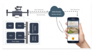
Figure 8: The conceptual design of the transmission line inspection robot
3.3. Purposed design
Figure 9 illustrates a design concept of an efficient robotic prototype for transmission line inspection with governing mechanism to transpose through obstacles on transmission lines. The model is designed and simulated using a special computer software. The robot consists of 6 linear actuators with the
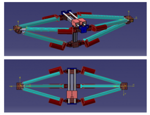
Figure 9: Design concept of the inspection robot
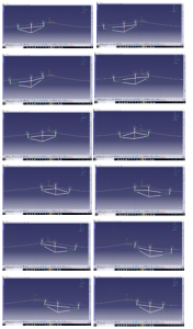
Figure 10: Transposition steps of the robot
maximum extension of 20 cm. They are used to control the front or back wheel towards the desired position. By connect 3 linear actuators together to from a parallel mechanism, the resulted actuator has very high stiffness and compact while the end-effector is still able to reach in required envelop. Moreover, there are 3 wheels for the driving of the robot. Each of wheel is installed with a driving motor which is a 200W BLDC hub motor installed inside the driving wheel set.
3.4. Motion of the robot and obstacles mitigation
The robot can shift its center of gravity to the front and rear by extending its arm to the desired direction. This enables the robot to lift the other arm out of the OHGW without losing stability.
The motion process is that the robot usually run along the OHGW and can transpose through obstacles, e.g. equipment and hardware on the structure with steps as the following:
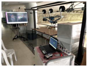
Figure 11: Laboratory test for the prototype with the line model
3.5. Kinematic model
The robot front and back arms are symmetric and identical. Each arm has three linear actuators arranged in the form of a tripod. The motion of the end effector can be described using coordinate system in the Figure 12.
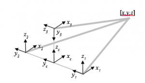
Figure 12: Coordinate system for each actuator and arm’s center and also the end-effector position.
The inverse kinematic model of each actuator is an actuator length ( ) as a function of the end-effector position in arm’s center frame ( ). There is a restriction in designing the end joint of the actuator which results in offsets between y and z rotation axis ( ). Since all actuators are identical, we can derive the model for all actuator in each actuator’s coordinate frame in the following:
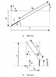
Figure 13: a) Side view and b) Top view of the mechanical model of a single linear actuator assembly
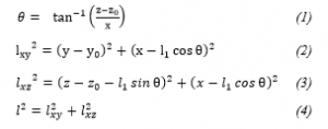
To verify the derived model, we commanded the end-effector to move in the form of geometric paths. We then recorded the movement using long-exposure snapshot which enables us to see the actual path taken. As a result, we found that the maximum available speed of the end-effector is 2 cm/sec. The speed beyond this number would result in linear actuator saturation and distortion in end-effector path.
3.6. Electronics
The control system for operation of robotic arms is for the front arm and the back arm. Each side consists of 3 linear actuators with DC motors and optical quadrature encoder to measure the position of the extended core. For the control system of motion, motors are grouped with 2 motors of each set. They are controlled via a Teensy 3.2 microcontroller which is a STM32 microcontroller with 96 MHz speed and with 2 quadrature encoder counters.
Operation and control board for the control system consists of Teensy 3.2 microcontroller and 2 motor driver boards VNH5019 assembled onto the circuit board, as shown in the Figure 15.
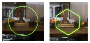
Figure 14: Actual path of the end-effector when tracing a 20mm radius circle at the speed of 2cm/s (left) and 4cm/s (right)
Figure 15: Operation and control board for the system
The control is commanded through the USB port to command the motor positon control program with PID control that is processed by microcontroller. The diagram for the operation of the motor control set is presented in the Figure 16.
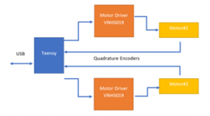
Figure 16: The diagram for the operation of the motor control set
All 3 motor control set are assembled altogether to control all 6 motors, and USB signal lines are connected through 4-port USB hub.
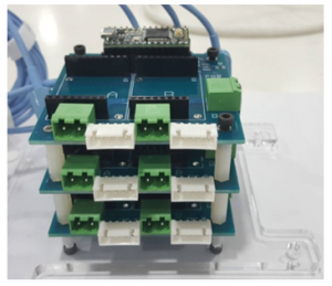
Figure 17: All motor control set are assembled altogether
Moreover, there is the fourth controller board. This board is used to control 3 BLDC motors. It is also equipped with inertial measurement module and load cells analog to digital converter to measure weight on each wheel for center of gravity calculation.
3.7. Software and control system
The main processor for this robot is an Industrial PC with Intel Core I5 processor running Ubuntu 18.04 as the operating system.
Operation and control program for the motion of the robot is constructed on the basis of Robotics Operating System (ROS) with the control structure in the Figure 18 below.
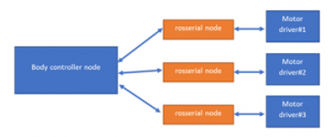
Figure 18: Operation and control program for the robot motion control
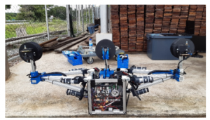
Figure 19: The developed inspection robot during set-up before the field test
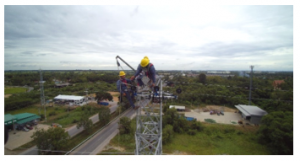
Figure 20: Actual field test on a 115 kV transmission line
4. Results
The invented pilot-line pulling robot was utilized to line pulling operations at many 115-kV transmission lines for different of maintenance jobs during 2016-2019. The results showed its capability on pulling the lead line/conductor along the OHGW effectively and was accredited for real workings with no more harm to landowner and can operate with safety and reliability. Examined results after achieving the tasks have proved about the robot’s performance on a pilot line pulling over the field with success. The robot can cut the personnel cost up to 34 less people and save the payment for damage’s properties. Fora direct output, the development of the robotic pilot-line pulling on the power line above the field can be achieved with no public concerns. For an indirect output, the electrical transmission network is safer and more dependable. Figure 7 demonstrates real implementation for inventive robot utilizations that pass the street, river, farmland, mountains, live switchyard, and electric power line. Also, the novel pilot line pulling robot was accredited as best practice by EGAT. The standards for invention, working, and maintenance were archived as references for transmission line operation and maintenance units nationally.
The inspection robot for transmission lines was specially designed for inspecting overhead power lines, running via the OHGW. Autonomous feature is a key challenge for developing the robot. Movement test was performed well on the simulated tower top for suspension type in the laboratory. After that, an actual field test was performed on July 2019 on suspension type and tension type towers of the real 115-kV power line. The observed results showed that the prototype of robot can run and transpose through actual obstacles like tested in the laboratory.
5. Conclusions
There is already evidence of different types of advanced robots designed and built by EGAT for the maintenance and inspection of high voltage transmission lines. The smart approach of work presently proposes the essential implementation of deploying innovative robots for approaches towards the smarter energy utility industry. The developed robots were successfully utilized to the actual transmission line in Thailand, causing tasks achieved with safety and reliability and without customer’s service interruption. In addition, it helps improve effectiveness by saving manpower and be an effective approach rectifying inspection precision while comparing to the convention one, such as ground patrolling. By utilization with the smart robots, power companies will save on routine line maintenance and inspection expenditure. Future development with highly advanced technology could be performed on the next generation of robot that can automatically climb the tower by itself.
Conflict of Interest
The authors declare no conflict of interest.
Acknowledgment
The researches were supported by the Electricity Generating Authority of Thailand and the Center of Excellence in Mathematics, the Commission on Higher Education, Thailand.
- EGAT Northern Region Operation Division, “The optical ground wire inspector robot: phra-siva vehicle,” Conference of Electric Power Supply Industry, 2008.
- FIBO, “A prototype of inspection robot for water wall tubes in boiler,” EGAT Final Research Report, 2014.
- NECTEC, “Development of a robot with thickness less than 2 centimeters for generator inspection,” EGAT Final Research Report, 2014.
- MTEC, “Development of robotic system for welding,” EGAT Final Research Report, 2013.
- MTEC, “Automatic overlay welding robot system for power plant parts phase II,” EGAT Final Research Report, 2017.
- T. Disyadej, J. Promjan, K. Poochinapan, T. Mouktonglang, S. Grzybowski and P. Muneesawang, “High Voltage Power Line Maintenance & Inspection by Using Smart Robotics,” 2019 IEEE Power & Energy Society Innovative Smart Grid Technologies Conference (ISGT), Washington, DC, USA, 2019, pp. 1-4, doi: 10.1109/ISGT.2019.8791584.
- S. Montambault and N. Pouliot, “LineScout Technology: Development of an Inspection Robot Capable of Clearing Obstacles While Operating on a Live Line,” ESMO 2006 – 2006 IEEE 11th International Conference on Transmission & Distribution Construction, Operation and Live-Line Maintenance, Albuquerque, NM, 2006, pp. , doi: 10.1109/TDCLLM.2006.340744.
- N. Pouliot and S. Montambault, “LineScout Technology: From inspection to robotic maintenance on live transmission power lines,” 2009 IEEE International Conference on Robotics and Automation, Kobe, 2009, pp. 1034-1040, doi: 10.1109/ROBOT.2009.5152291.
- N. Pouliot, P. Latulippe and S. Montambault, “Reliable and intuitive teleoperation of LineScout: a mobile robot for live transmission line maintenance,” 2009 IEEE/RSJ International Conference on Intelligent Robots and Systems, St. Louis, MO, 2009, pp. 1703-1710, doi: 10.1109/IROS.2009.5354819.
- S. Montambault, N. Pouliot, J. Toth and B. Spalteholz, “Reporting on a large ocean inlet crossing live transmission line inspection performed by linescout technology,” 2010 IEEE International Conference on Robotics and Automation, Anchorage, AK, 2010, pp. 1102-1103, doi: 10.1109/ROBOT.2010.5509190.
- S. Montambault and N. Pouliot, “Field experience with LineScout Technology for live-line robotic inspection and maintenance of overhead transmission networks,” 2010 1st International Conference on Applied Robotics for the Power Industry, Montreal, QC, 2010, pp. 1-2, doi: 10.1109/CARPI.2010.5624454.
- J. Toth, N. Pouliot and S. Montambault, “Field experiences using LineScout Technology on large BC transmission crossings,” 2010 1st International Conference on Applied Robotics for the Power Industry, Montreal, QC, 2010, pp. 1-6, doi: 10.1109/CARPI.2010.5624413.
- N. Pouliot, D. Mussard and S. Montambault, “Localization and archiving of inspection data collected on power lines using LineScout Technology,” 2012 2nd International Conference on Applied Robotics for the Power Industry (CARPI), Zurich, 2012, pp. 197-202, doi: 10.1109/CARPI.2012.6473341.
- S. Montambault, N. Pouliot and M. Lepage, “On the latest field deployments of LineScout Technology on live transmission networks,” 2012 2nd International Conference on Applied Robotics for the Power Industry (CARPI), Zurich, 2012, pp. 126-127, doi: 10.1109/CARPI.2012.6473342.
- S. Montambault and N. Pouliot, “About the future of power line robotics,” 2010 1st International Conference on Applied Robotics for the Power Industry, Montreal, QC, 2010, pp. 1-6, doi: 10.1109/CARPI.2010.5624466.
- P. Debenest et al., “Expliner – Robot for inspection of transmission lines,” 2008 IEEE International Conference on Robotics and Automation, Pasadena, CA, 2008, pp. 3978-3984, doi: 10.1109/ROBOT.2008.4543822.
- P. Debenest and M. Guarnieri, “Expliner — From prototype towards a practical robot for inspection of high-voltage lines,” 2010 1st International Conference on Applied Robotics for the Power Industry, Montreal, QC, 2010, pp. 1-6, doi: 10.1109/CARPI.2010.5624434.
- A. Phillips, E. Engdahl, D. McGuire, M. Major and G. Bartlett, “Autonomous overhead transmission line inspection robot (TI) development and demonstration,” 2012 2nd International Conference on Applied Robotics for the Power Industry (CARPI), Zurich, 2012, pp. 94-95, doi: 10.1109/CARPI.2012.6473343.
- Tang Li, Fang Lijin and Wang Hongguang, “Obstacle-navigation control for a mobile robot suspended on overhead ground wires,” ICARCV 2004 8th Control, Automation, Robotics and Vision Conference, 2004., Kunming, China, 2004, pp. 2082-2087 Vol. 3, doi: 10.1109/ICARCV.2004.1469485.
- Tang Li, Fang Lijin and Wang Hongguang, “Development of an inspection robot control system for 500KV extra-high voltage power transmission lines,” SICE 2004 Annual Conference, Sapporo, 2004, pp. 1819-1824 vol. 2.
- Tang Li, Fu Shuangfei, Fang Lijin and Wang Hongguang, “Obstacle-navigation strategy of a wire-suspend robot for power transmission lines,” 2004 IEEE International Conference on Robotics and Biomimetics, Shenyang, 2004, pp. 82-87, doi: 10.1109/ROBIO.2004.1521756.
- W. Hongguang, J. Yong, L. Aihua, F. Lijin and L. Lie, “Research of power transmission line maintenance robots in SIACAS,” 2010 1st International Conference on Applied Robotics for the Power Industry, Montreal, QC, 2010, pp. 1-7, doi: 10.1109/CARPI.2010.5624428.
- X. Xiao, G. Wu and S. Li, “Dynamic Coupling Simulation of a Power Transmission Line Inspection Robot with its Flexible Moving Path when Overcoming Obstacles,” 2007 IEEE International Conference on Automation Science and Engineering, Scottsdale, AZ, 2007, pp. 326-331, doi: 10.1109/COASE.2007.4341691.
- G. Wu, X. Xiao and Y. Lai, “A Wheel-Claw Hybrid Manipulator and its Grasping Stability for the Mobile Robot Rolling/Crawling Along Flexible Cable,” 2007 International Workshop on Robotic and Sensors Environments, Ottawa, Ont., 2007, pp. 1-6, doi: 10.1109/ROSE.2007.4373964.
- J. Guo et al., “Database Environment of an Inspection Robot for Power Transmission Lines,” 2009 Asia-Pacific Power and Energy Engineering Conference, Wuhan, 2009, pp. 1-4, doi: 10.1109/APPEEC.2009.4918249.
- G. Wu et al., “Design and Application of Inspection System in a Self-Governing Mobile Robot System for High Voltage Transmission Line Inspection,” 2009 Asia-Pacific Power and Energy Engineering Conference, Wuhan, 2009, pp. 1-4, doi: 10.1109/APPEEC.2009.4918256.
- Gongping Wu, Tuo Zheng, Hua Xiao and Cheng Li, “Navigation, location and non-collision obstacles overcoming for high-voltage power transmission-line inspection robot,” 2009 International Conference on Mechatronics and Automation, Changchun, 2009, pp. 2014-2020, doi: 10.1109/ICMA.2009.5245998.
- C. Hu, G. Wu, H. Cao and X. Xiao, “Obstacle Recognition and Localization Based on the Monocular Vision for Double Split Transmission Lines Inspection Robot,” 2009 2nd International Congress on Image and Signal Processing, Tianjin, 2009, pp. 1-5, doi: 10.1109/CISP.2009.5303695.
- Gongping Wu, Tuo Zheng, Zhenglie Huang, Huan Liu and Cheng Li, “Navigation strategy for local autonomous obstacles-overcoming based on magnetic density detection for inspection robot of single split high voltage transmission line,” 2010 8th World Congress on Intelligent Control and Automation, Jinan, 2010, pp. 6555-6561, doi: 10.1109/WCICA.2010.5554409.
- X. Xu, G. Wu, Y. He, X. Xiao, M. Liu and Q. Liu, “Navigation and control for a novel ground line inspection robot,” 2010 IEEE International Conference on Mechatronics and Automation, Xi’an, 2010, pp. 1228-1232, doi: 10.1109/ICMA.2010.5589954.
- Naresuan University, “Development of mobile robot for inspection of high voltage transmission line,” EGAT Research Proposal, 2018.