
Design and Optimization of Dual-Band Branch-Line Coupler with Stepped-Impedance-Stub for 5G Applications
Volume 5, Issue 3, Page No 355-360, 2020
Author’s Name: Ayyoub El Berbri1,a), Adil Saadi1, Seddik Bri2
View Affiliations
1Control, Pilotage and Supervision of Systems, National Graduate School of Arts and Crafts, Moulay Ismail University, Meknes, Morocco
2Materials and Instrumentation, High School of Technology, Moulay Ismail University, Meknes, Morocco
a)Author to whom correspondence should be addressed. E-mail: ayyoub.elberbri@gmail.com
Adv. Sci. Technol. Eng. Syst. J. 5(3), 355-360 (2020); ![]() DOI: 10.25046/aj050346
DOI: 10.25046/aj050346
Keywords: Optimization, Tuning, Dual-Band, Branch-Line Coupler, 5G

Export Citations
This paper presents a design optimization of a dual-band branch-line coupler with stepped-impedance-stub lines. This coupler operates over 5G NR frequency bands n5 and n2, developed by 3GPP for the 5G (fifth generation) mobile network, and these two bands are centered at 0.85 GHz and 1.9 GHz respectively. To achieve the design specifications an adjusted Tuning Space Mapping method is used. This method of optimization moves the hardship of optimization from high-fidelity electromagnetic models to low-fidelity tuning models. The simulated and measured results of this enhanced coupler show good dual-band performance at the two bands.
Received: 21 January 2020, Accepted: 23 May 2020, Published Online: 11 June 2020
1. Introduction
The request for mobile communication is more than ever. For this reason, many researchers have focused on the development of a new generation of communication. 5G NR is a new radio access technology developed by 3GPP for the 5G mobile network. We designed the coupler to function in the two bands n5 and n2 from the 3GPP TS 38.101 [1].
Branch-line couplers (BLC) offer a π/2 power splitting and phase difference, which is suitable in different microwave circuits like power combined amplifiers, phase shifters, data modulators, and balanced mixers [2]. There are different dual-band BLC design that exists in the literature [3-9]. In this work, we use stepped-impedance-stub branches lines (SISBL) for dual-band operation. [10].
This work presents the design of a dual-band BLC with SISBL, designed for 5G NR frequency bands downlink [n2= (0.869 –0.894 GHz) / (n5= (1.930–1.990 GHz)], this bands developed by 3GPP for the 5G (fifth generation) mobile network and centered at 0.85 GHz and 1.9 GHz respectively [1].5G NR, like most modern techniques, demands height accuracy. In many situations like ours, due to microwave structure complexity of SISBL dual-band BLC, the theoretical model only gives the initial design that requires optimization so he can meet the design specifications. In our case, for the optimization, we use an adjusted Tuning Space Mapping, the adjustment is made in the tuning model using our engineering expertise and knowledge of the design problem. The advantage is to reduce time-consuming. The enhanced characteristics of this Dual-Band BLC with SISBL are presented.
The simulated results of this enhanced dual-band BLC show good dual-band performances at n5/n2. The performance of its fabricated prototype has also been validated experimentally.
2. Dual-Band BLC with SISBL
Figure 1.a presents the SISBL containing a signal path (Z3, θ3) tapped with (Z1, θ1) and (Z2, θ2) [10]. By multiplying the ABCD matrices of each cascade component, the ABCD matrix of the SISBL is reached. Since the dual-band branch line behaves as a π/2 line at center frequencies of the two bands (fp and fs), the ABCD matrix is formulated as (1).
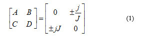
Where J the characteristic admittance of the π/2 line
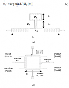
Figure 1. a: Dual-band SISBL; b: The dual-band BLC with SISBL.
The circuit dimensions of the SISBL Figure 1.b can be determined by solving the following equations (1)-(4). Where (θ1, θ2, θ3) the electrical lengths of the lines (1,2,3) respectively, and (Z1, Z2, Z3) the impedances of the lines (1,2,3).
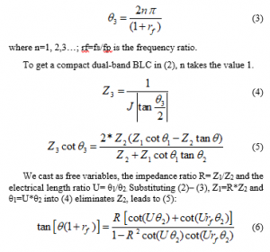
Equation (4) has only θ2 for variable since the constants U, R and rf can be pre-chosen. θ2 is found using the graph of each side of the equation (4).
Figure 2 presents the variation of the impedances Z1 and Z2 versus frequency ration rf when R and U are both 0.2. That figure shows that both Z1 and Z2 increase as rf increases. Since only an impedance of 20–120 Ω can be realized using microstrip, the range of rf is limited to 1.9<rf<2.5.
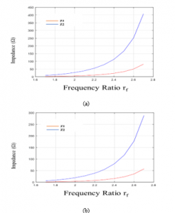
Figure 2: Variation of Z1 and Z2 versus rf. (a) Dual-band 50 Ω branch line. (b). Dual-band 50/√2 Ω branch line
3. Tuning Space Mapping
The utilize of electromagnetic software for design optimization can be problematic, because EM simulations are rigorous. By shifting the optimization load onto a coarse model, for example, a circuit equivalent, space mapping (SM) reduces the computational rate of EM simulation. Over an iterative optimization and updating of the low fidelity models, SM achieves efficient optimization. [11].
Tuning space mapping such as SM belongs to a family of surrogate-based optimization techniques [12-23]. However, the role of the surrogate model is replaced by a so-called tuning model. By introducing tuning components (circuit-theory base components) into the fine model structure, the tuning model is built up. The original optimization problem is as follow [15]:
Where Rf ∈ Rm is the response vector, U is an objective function, x is the vector of design parameters, and is the optimal solution.
At i-th iteration, a tuning model is constructed based on the fine model data. The alignment process to eliminate the gap between the tuning model response and the response of the fine model at i, it is formulated as:
4. Results and Discussion
We chose (U, R) = (0.2,0.2), the dimensions of this dual-band BLC have been computed with the use of (2)-(5). Figure 3 illustrates the intersecting points of each side of the equation (4).
The length electric from Figure 3 is θ2=72.68°. The other circuit dimensions (Z1, θ1, Z2, Z3, θ3) of both the 50Ω and 50Ω/√2 branches of the coupler are computed from equations (2), (3) and (4).
The design parameters are x = [L0 L11 L21 L31 L12 L22 L32] T mm. The fine model, as shown in Figure 4, is simulated using a substrate of εr = 4, height H =1.4 mm and loss tangent= 0.0004.
Figure 6 shows that S11 and S14 for the second band are below -10dB from 1.76 GHz to 1.88GHz, this is not the entire [1.930 GHz–1.990 GHz] band. And in the same range, the phase difference between output ports (2 and 3) is not 90 °± 10°. For better performance, optimization is needed.
To build the tuning model, we first simulate the fine model with the co-calibrated ports Figure 5, the corresponding S44P data file is charged into a 44-port S-parameter file component in the tuning model. After that, an appropriate circuit component is attached to the corresponding ports on the S-parameter component; the tuning parameters are xt = [Lt0 Lt11 Lt21 Lt31 Lt12 Lt22 Lt32] Tmm.
The tuning parameters obtained after optimized the tuning model are xt.1 (0) = [0.632 -0.73 -2.583 0.343 -2.945 -1.291 -3.884] Tmm. With the use of a direct calibration the optimal values of the tuning parameters are converted to the adjustments of the design parameters in a direct manner. After the first iteration, the new design x (1) = [50.9392 6.75824 38.7104 61.2757 4.45566 38.9794 51.5329] T mm has already satisfied the design specifications Figure 7.
Figure 7 shows that the simulated S11 and S14 are less than -11dB, within the frequency range of 0.82-0.92 GHz (first band), and within 1.88-2 GHz (second band). Within a similar frequency range, the coupling coefficient is 3 ± 1 dB, the transmission coefficient is 3 ± 1 dB, and the phase difference between output ports (2 and 3) is 90 °± 10°. TABLE I summarized the performances of this dual-band BLC.
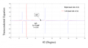
Figure 3: Solutions to (4) for θ2 of SISBL
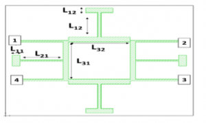
Figure 4: The fine model.
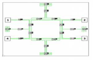
Figure 5: The fine model divided
Figure 8 shows the photograph of the prototype of the enhanced dual-band BLC fabricated using an LPKF machine. As we can see, its structure is relatively simple as it can be fabricated on a single layer printed circuit board with a simple ground plane.
The measurements of the fabricated prototype are done using 1-Port USB Vector Network Analyzer. Figure 9 plots the simulated and measured (S11), it shows that there is a good match between simulated and measured S11 of this enhanced dual-band BLC.
TABLE I summarized, the results of the simulation for the initial and the optimized dual-band BLC performance, also the measurements of the fabricated prototype. The optimized dual-band BLC shows better performances for both 5G NR bands, which the initial does not do.
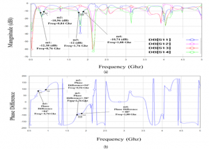
Figure 6. The Initial fine model response; a:S-paramertres b: phase difference between Port2 and 3
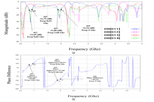
Figure 7: The Optimized fine model response; a:S-paramertres b: phase difference between Port2 and 3.
Table 1: The simulated and measured results
| Parameter |
Initial First band |
Initial Second band |
Optimized First band |
Optimized Second band |
Measured First band |
Measured Second band |
| S11 (dB) | <-10 dB | <-10 dB | <-10dB | <-10dB | <-10dB | <-10dB |
| S12 (dB) | 3 ± 1 dB | 3 ± 1 dB | 3 ± 1 dB | 3 ± 1 dB | – | – |
| S13 (dB) | 3 ± 1 dB | 3 ± 1 dB | 3 ± 1 dB | 3 ± 1 dB | – | – |
| S14 (dB) | <-10 dB | <-10 dB | <-10dB | <-10dB | <-10dB | <-10dB |
|
Phase difference |
90° ± 10° | 90° ± 10° | 90° ± 10° | 90° ± 10° | – | – |
|
Operating frequency (GHz) |
0.76-0.84 | 1.76-1.88 | 0.8-0.92 | 1.88-2 | 0.8-0.94 | 1.84-2.04 |
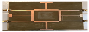
Figure 8: Photograph of the fabricated prototype
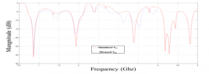
Figure 9: simulated and measured S11
5. Conclusion
A dual-band BLC with SISBL for 5G NR applications has been designed. The coupler performance is further improved through optimization of his physical dimensions, using an adjusted Tuning Space Mapping to work for more complex microwave circuits such as our design. The simulated and measured results show that S11 are less than -11dB, within the frequency range of 0.82-0.92 GHz (first band), and within 1.88-2 GHz (second band). The method used permits rapid optimization with accurate results obtained after only one iteration.
- 3GPP specification series: 38series.url: https://www.3gpp.org/DynaReport/ 38-series.htm (visited on 20/17/2020)
- D. M. Pozar, Microwave Engineering, 4th ed. New York: Wiley, 2012.
- M.-J. Park and B. Lee, “Dual-band, cross coupled branch line coupler” IEEE Microw. Wireless Compon. Lett., 15(10), 655–657, 2005. https://doi.org/10.1109/LMWC.2005.856683
- I.-H. Lin, M. DeVincentis, C. Caloz, and T. Itoh, “Arbitrary dual-band components using composite right/left-handed transmission lines” IEEE Trans. Microw. Theory Tech., 52(4), 1142–1149, 2004. https://doi.org/10.1109/TMTT.2004.825747
- J.-X. Niu and X.-L. Zhou, “A novel dual-band branch line coupler based on strip-shaped complementary split ring resonators” Microw. Opt. Technol. Lett., vol. 49(11), 2859–2862, 2007. https://doi.org/10.1002/mop.22873
- K.-K. M. Cheng and F.-L. Wong, “A novel approach to the design and implementation of dual-band compact planar 90 branch-line coupler” IEEE Trans. Microw. Theory Tech., 52(11), 2458–2463, https://doi.org/10.1109/TMTT.2004.837151
- C. Collado, A. Grau, and F. D. Flaviis, “Dual-band planar quadrature hybrid with enhanced bandwidth response” IEEE Trans. Microw. Theory Tech., 54(1), 180–188, 2006. https://doi.org/10.1109/TMTT.2005.860306
- K.-K. M. Cheng and F.-L. Wong, “Dual-band rat-race coupler design using tri-section branch-line” Electron. Lett., 43(6), 41–42, Mar. 2007. https://doi.org/10.1049/el:20070018
- C.-L. Hsu, J.-T. Kuo, and C.-W. Chang, “Miniaturized dual-band hybrid couplers with arbitrary power division ratios” IEEE Trans. Microw. Theory Tech., 57(1), 49–156, 2009. https://doi.org/10.1109/ TMTT. 2008.2009036
- K.-S Chin, K.-M. Lin, Y.-H. Wei, T.-H. Tseng, Y.-J. Yang “Compact Dual-Band Branch-Line and Rat-Race Couplers with Stepped-Impedance-Stub Lines “IEEE Transactions on Microwave Theory and Techniques, 58(5), 2010. https://doi.org/10.1109/ TMTT.2010.2046064
- J. Meng, S. Koziel, J.W. Bandler, M.H. Bakr, and Q.S. Cheng, “Tuning space mapping: a novel technique for engineering optimization” in 2008 IEEE MTT-S International Microwave Symposium Digest, Atlanta, GA, USA, 2008. https://doi.org/10.1109/MWSYM.2008.4633001
- D. Echeverria, P.W. Hemker, “Space mapping and defect correction,”The International Mathematical Journal Computational Methods in Applied Mathematics, 5(2), 107–136, 2008. https://doi.org/10.1007/978-3-540-78841-6_8
- M.A. Ismail, D. Smith, A. Panariello, Y Wang, and M. Yu, “EM-based design of large-scale dielectric-resonator filters and multiplexers by space mapping” IEEE Trans. Microwave Theory Tech., 52(1), 386–392, 2004. https://doi.org/10.1109/TMTT.2003.820900
- T.W. Simpson, J. Peplinski, P.N. Koch, and J.K. Allen, “Metamodels for computer-based engineering design: survey and recommendations” ENG. COMPUT., 17(2), 129–150, 2001. https://doi.org/10.1007/PL00007198
- J.W. Bandler, R.M. Biernacki, S.H. Chen, P.A. Grobelny, and R.H. Hemmers, “Space mapping technique for electromagnetic optimization” IEEE T. MICROW. THEORY., 42(12), 2536–2544, 1994. https://doi.org/10.1109/22.339794
- N.V. Queipo, R.T. Haftka, W. Shyy, T. Goel, R. Vaidynathan, and P.K. Tucker, “Surrogate-based analysis and optimization,” PROG. AEROSP. SCI., 41(1), 1–28,2005.https://doi.org/10.1016/j.paerosci.2005.02.001
- S. Koziel, J.W. Bandler, A.S. Mohamed, and K. Madsen, “Enhanced surrogate models for statistical design exploiting space mapping technology” in IEEE MTT-S International Microwave Symposium Digest, Long Beach, CA, USA, 2005. https://doi.org/10.1109/MWSYM.2005.1517012
- S. Koziel, J.W. Bandler, and K. Madsen, “Theoretical justification of spacemapping-based modeling utilizing a data base and on-demand parameter extraction” IEEE T. MICROW. THEORY., 54(12), 4316–4322, 2006. https://doi.org/10.1109/TMTT.2006.884648
- S. Koziel and J.W. Bandler, “Microwave device modeling using spacemapping and radial basis functions” in 2007 IEEE/MTT-S International Microwave Symposium, Honolulu, HI, 2007. https://doi.org/10.1109/MWSYM.2007.380079
- V.K. Devabhaktuni, B. Chattaraj, M.C.E. Yagoub, and Q.-J. Zhang, “Advanced microwave modeling framework exploiting automatic model generation, knowledge neural networks, and space mapping” IEEE T. MICROW. THEORY., 51(7), 1822–1833, 2003. https://doi.org/10.1109/MWSYM.2002.1011836
- A. SAADI, S. BRI,” Non-Linear Optimization of Small Size Microwave Directional Coupler Design Using Implicit Space” Int. J. Microw. Appl., Volume 2(4), 2013. http://warse.org/pdfs/2013/ijma022420 13.pdf
- F. Feng; C. Zhang; W. Na; J. Zhang; W. Zhang; Q.-J; Zhang, “Adaptive Feature Zero Assisted Surrogate-Based EM Optimization for Microwave Filter Design” IEEE MICROW. WIREL. CO., 29(1), 2-4, 2019. https://doi.org/10.1109/LMWC.2018.2884643
- B. Liu, V. Grout, A. Nikolaeva, “Efficient Global Optimization of Actuator Based on a Surrogate Model Assisted Hybrid Algorithm” IEEE T. IND. EL. CON. IN., 65(7), 5712-5721, 2018. https://doi.org/10.1109/TIE.2017.2782203