ANN Based MRAC-PID Controller Implementation for a Furuta Pendulum System Stabilization
 , German Baltazar-Reyes, Israel Macias, Adriana Vargas-Martinez, Jorge de Jesus Lozoya-Santos, Ricardo Ramirez-Mendoza, Ruben Morales-Menendez, Arturo Molina
Adv. Sci. Technol. Eng. Syst. J. 5(3), 324–333 (2020);
 DOI: 10.25046/aj050342
Nowadays, process automation and smart systems have gained increasing importance in a wide variety of sectors, and robotics have a fundamental role in it. Therefore, it has attracted greater research interests; among them, Underactuated Mechanical Systems (UMS) have been the subject of many studies, due to their application capabilities in different disciplines. Nevertheless, control of UMS is remarkably more difficult compared to other mechanical systems, owing to their non-linearities caused by the presence of fewer independent control actuators with respect to the degrees of freedom of the mechanism (which characterizes the UMS). Among them, the Furuta Pendulum has been frequently listed as an ideal showcase for different controller models, controlled often through non-lineal controllers like Sliding-Mode and Model Reference Adaptive controllers (SMC and MRAC respectively). In the case of SMC the chattering is the price to be paid, meanwhile issues regarding the coupling between control and the adaptation loops are the main drawbacks for MRAC approaches; coupled with the obvious complexity of implementation of both controllers. Hence, recovering the best features of the MRAC, an Artificial Neural Network (ANN) is implemented in this work, in order to take advantage of their classification capabilities for non-linear systems, their low computational cost and therefore, their suitability for simple implementations. The proposal in this work, shows an improved behavior for the stabilization of the system in the upright position, compared to a typical MRAC-PID structure, managing to keep the pendulum in the desired position with reduced oscillations. This work, is oriented to the real implementation of the embedded controller system for the Furuta pendulum, through a Microcontroller Unit (MCU). Results in this work, shows an average 58.39% improvement regarding the error through time and the effort from the controller.
1. Introduction
In recent decades, robotics have gained increasing importance in endless applications for different disciplines (as explained in [1]); such as, robotic manipulators for industrial automation, precision robots to perform surgeries, automation of assembly lines, among others. Thus, robotics have attracted greater interest multidisciplinary researchers.
Moreover, according to [2], it is defined in robotics that an Underactuated Mechanical System (UMS), is a scheme with more Degrees of Freedom (DOF) compared to its control actuators. Additionally, [3] explains that the control of UMS’s is a very active research topic, due to their broad applications in Robotics, Aerospace, and Marine Vehicles.
low number of required actuators that makes UMS’s ideal for applications where energy efficiency is sought. Additionally, UMS’s are systems that allow to decrease the size of the manipulators, and even simplify the amount of elements of a more complex system. The above, resulting also in cost reduction with an increased process efficiency, which is the key element that attracts the most interest for its development in the industry.
The non-linearities caused by the relation between the actuators and the DOF to be controlled, makes the complexity of these systems attractive as testbeds, for the research of different control structures. Among them, this work is focused in the rotatory pendulum, also known as the Furuta Pendulum (in honor of its inventor K.
Furuta [4]), which is a highly non-linear system that is unstable at the desired upright position, as described in [3].
Hence, different solutions have been proposed addressing the swinging-up and the upright issues of the Furuta Pendulum, which are the main control objectives to fulfill in order to achieve the desired position. In the case of the stabilization issue, [5] proposes a Linear Quadratic Regulator (LQR) approach, showing a better settling time with low overshoots, regarding a Sliding-Mode Controller (SMC). Nevertheless, solutions that require linearized equations are more effective when the non-linear components of the system, are small regarding the linear predominant behavior; therefore, in high non-linear systems like the Furuta Pendulum, the control structure may be highly sensitive to parametric variations, compromising the behavior of the controller when additional friction coefficients, unexpected center of mass changes in the real, or even the uncertainty of the linearized model, are presented.
Therefore, many other approaches based on nonlinear controllers are still being studied, as shown in [6] and [7] applications, where the implementation of the SMC and an Integral Sliding Mode Controller (ISMC) for pendulum stabilization are presented respectively, showing that the (ISMC) has the best response regarding perturbations rejection. Nevertheless, the chattering continues to be a limitation regarding to practical limitations of actuators, as explained in [8].
On the other hand, [9] presents a Model Reference Adaptive Controller (MRAC) implementation, discussing the implementation of the technique compared again to an LQR approach. In this particular case, it is shown that the LQR controller had an improved behavior regarding the settling time of the MRAC controller through the MIT rule, nevertheless perturbation rejection tests where not clearly analyzed.
Additionally, other studies such as [10], validates that the adaptive features of the MRAC can create a more robust system, features that are also translated to all the MRAC derivations. The previous premise can be clearly validated by the work presented in [11], where an MRAC combined with a Proportional Integrative Derivative (MRAC-PID) is implemented in a real Furuta pendulum testbed, achieving through the simulated and the experimental responses the validation of the method, for the upright stabilization issue of the pendulum.
Henceforth, it is important to highlight that this paper is an extension of the [11] work, originally presented in the ICMEAE 2019 (6th International Conference on Mechatronics, Electronics and Automatation Engineering) and ICCRE 2019 (4th International Conference on Control and Robotics Engineering); where the design, modelling and a first control approach for the Furuta Pendulum was presented.
Nevertheless, the [11] implementation had its main drawback, in the great amount of processing resources consumed from the Microcontroller Unit (MCU), which in some instances compromised the correct and precise sampling rate of the data, which leaded to unexpected noise in the error signal and therefore to practical issues in the implementation. Therefore, this proposal takes the obtained results from the MRAC-PID approach, improving the behavior of the system through the implementation of an ANN based controller.
Controllers based on ANN are able to provide robust, nonfluctuating performances in the presence of parametric uncertainty and extraneous disturbances, as explained in [12] where an ANN was simulated in order to validate its capabilities for UMS. However, the methodology was only simulated, and therefore there was none experimental validation of the performance of the control theory.
On the other hand, the main objective of designed ANN in this work, is to emulate the behavior of the MRAC-PID controller implemented in [11], extending the operating margins and maintaining the stability gained by the original MRAC-PID, but with lower computational effort; which is indeed, a common characteristic of the implementation of ANN’s (as discussed in [13] and [10]).
In this particular proposal, the ANN is not trained through a model oriented approach as in [12]; in this work, the model of the Furuta pendulum was taken for the MRAC-PID controller calibration and implementation, and the ANN was trained through the acquired data from the experimental testbed, expecting to achieve a correct emulation of the controller’s behavior, but improving its performance by increasing response speed of the controller through the reduction of the required embedded processing effort.
Then, the results in this work where acquired through the embedded implementation in the real experimental testbed. It is critical for this work to highlight that, the ANN is trained through the input/output data acquired from the stabilization MRAC-PID controller implemented in [11], in order to achieve the improved behavior of the controller with less computational effort.
Therefore, the control effort is validated through the evaluation of the control signal through time, where the duty cycle sent to the driver of the actuator can be evaluated for the task. Meanwhile, the performance is evaluated by the evolution of the error through time. Together, both signals allow evaluating the performance of the system and, the actuator stress required to achieve the control objective.
Hence, this work presents in Section 2 the control objectives of the Furuta Pendulum with greater details, meanwhile the experimental testbed is presented in Section 3; Section 4 discusses the structure of the MRAC-PID control topology, leading to the ANN concepts discussed in Section 5. Finally, Section 6 presents the results of this work and Section 7 presents the final conclusion.
2. Furuta Pendulum
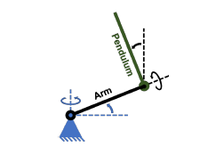
Figure 1: Basic Furuta Pendulum diagram.
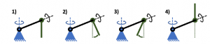
Figure 2: Swinging-up sequence for the Pendulum.
As explained in [14], the rotatory inverted pendulum (also known as the Furuta Pendulum), is a rotatory system composed by an homogeneous pendulum attached to a perpendicular arm, which rotates in a horizontal plane. Fig. 1 shows the basic configuration of the pendulum, where the blue triangle represents the fixed point in which the arm is attached, therefore the first DOF of the system is in the arm, that can only rotate around the vertical axis, in the horizontal plane.
Moreover, also from Fig. 1 can be seen that the pendulum is coupled to the arm by means of a bearing, which allows it to rotate around the arm axis and therefore, it is there where the next degree of freedom of the system is found. Henceforth, attending to the UMS classification in which the Furuta Pendulum is located in, the only actuator of the system is attached in the fixed point at the beginning of the arm.
1.1 Control Objectives
As implied from the structure of the Furuta Pendulum, it is clear that it is a system that is unstable without a controller (as also explored in [15]). Thus, the control objectives of a Furuta Pendulum can be divided into two main issues, as addressed in [11], where they have been extensively studied both individually and together.
On the one hand, the initial state of the Furuta pendulum is just as shown in the first diagram of Fig. 2, where the pendulum is in its resting position. The control objective there, is located in the natural equilibrium point; in this scenario, a controller needs to be applied in order to destabilize the system by applying torque to the arm through the actuator, traduced into a swing-up routine, by then, arising the pendulum into the working range of the main stabilization controller.
The swing-up routine can be summarized by the second and third diagrams of Fig. 2, finally leading to the stage of the fourth diagram, where the pendulum switches to the controller in charge of maintaining the upright position. The swinging-up routine can be made through energy control, as explored by Furuta itself in [4]. Other proposed solutions for the task is the predictive controller
([16]), and even solved through feedforward approaches such as presented in [17].
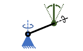
Figure 3: Representation of the stabilization objective.
On the other hand, the second control objective lies in the stabilization of the pendulum, in order to maintain it in an upright position by correcting any disturbance, only through the applied torque of the arm. Fig. 3, shows the basic outline of the control objective, where the green doted lines represent the operating range that delimits the control actions, knowing that most of the state of the art recommends it to be maximum ±15o from the upright position.
Therefore, summarizing the control objectives, out of the stabilization range the swing-up controller is activated, in order to take the pendulum into the area in which the stabilization controller takes the wheel, achieving then the expected upright position.
In addition, the study of controllers in charge of maintaining the pendulum in the upright position, have served for inspiration of many applications, such as the stability of walking humanoid robots among others. Hence, this work proposal is focused in a solution regarding the stabilization control objective, where ANN based controller seeks to achieve an effective solution for its microcontroller implementation.
2.2 System Modelling
As explained in [11], the mathematical model of the system can be delivered by the segmentation of the mechanical system, through its kinetic and potential energy (as discussed in [4]. Therefore, the energies relation from which the mathematical model of the pendulum emerges, is given by (1).
![]()
where L is the Lagrange relation obtained by combining both energy equations, Karm and kp are the kinetic energy equations of the arm and the pendulum respectively, meanwhile Varm and Vp are their potential energy equations. After the kinetic and potential energies analysis, as explained in [18] and also validated by [11], the expansion of (1) leads to second order differential equations; the first one, is the differential equation of the motion of the pendulum in terms of the angle generated between the horizontal plane and the pendulum’s arm (θarm). Meanwhile, the second one is the differential equation obtained from the motion of the system, in terms of the pendulum and the angle between the vertical axis and the pendulum itself (θp).
The simplified expression that describes the behavior of (θarm), is given by (2). Where α and β are products of a change of variable, since α is the expansion given by (3), and β is developed through
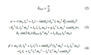
On the other hand, the behavior of (θp) is given by (5). Where another change of variable was made in order to simplify the expression, as explored in (2). Therefore in this case, γ is given by the expression given by (6), meanwhile λ is traduced as (7).
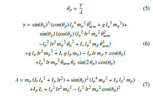
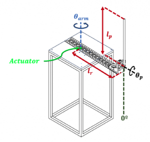
Figure 4: Representation of the stabilization objective.
In terms of the testbed analyzed in this paper, the variables from
(2) and (5) are sketched in the diagram shown in Fig. 4, where an isometric view of the designed 3D model of the pendulum is used, design that will be explained in more detail later in this document.
Nevertheless, all the variables of the equations presented in this section and analyzed in Fig. 4, are summarized in Table 1. Additionally, Table 1 shows the parameters of the each variable in the implemented experimental testbed, which is explained in Section 3.
Table 1: Furuta Pendulum Variables
| Variable | Description | Value |
| mr | Arm mass | 0.35 [kg] |
| mp | Pendulum mass | 0.12 [kg] |
| lr | Arm length | 0.15 [m] |
| lp | Pendulum length | 0.25 [m] |
| Ir | Arm moment of inertia | 0.02 [kgm2] |
| Ip | Pendulum moment of inertia | 0.001 [kgm2] |
| τ | Nominal Torque | 0.09 [Nm] |
| θarm | Arm angle | – [rad] |
| θp | Pendulum angle | – [rad] |
It is important to highlight that in this application, the arm length lr is measured as the distance from the center of the actuator shaft to the location of the pendulum. On the other hand, the length of the pendulum is taken as the length of the pendulum bar, from the point where it is attached to the system. Nevertheless, the center of mass of the pendulum is found as the half of the pendulum’s length.
3. Experimental Testbed
The designed testbed, was inspired by the one implemented in the short version of this work ([11]), where basically the mechanical design is described in Fig. 5.
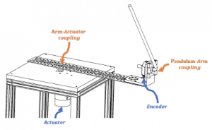
Figure 5: Schematic of the component assembly for the testbed.
The selected actuator, was the Pololu 12V, 19:1 Gear Motor w/ 64 CPR Encoder, which is a DC motor with a gearbox, that already has a two phase encoder for speed measurements that also has a
5A stall Current, same that is activated and controlled thorough a MD30C 30A DC Motor Driver.
Additionally, the control signal of the system, the signals processing and data acquisition, are made by the FRDM-K64F development board, which has an MK64FN1M0VLL12 microcontroller that works at 120MHz, with 1024KB of Flash memory, 256KB SRAM memory, and also allows an easier implementation of the equations through its integrated Floating Point Unit (as explored in [11]).
It is important to highlight that the original version of this work ([11]), was programmed using FreeRTOS (Free Real-Time Operating System), in order to work with a better sample time response from the microcontroller and a faster control output signal. Nevertheless, several changes were made in order to improve the sampling rate and therefore the error post-processing. The main changes, lie in the implementation of a Periodic Interrupt Timer (PIT), which generates highly precise interrupts at regular intervals with minimal processor intervention, therefore allowing to exploit more resources for the controller implementation.
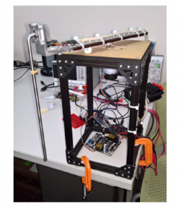
Figure 6: Experimental testbed designed and implemented.
On the other hand, for the pendulum’s data acquisition, a modular-incremental encoder was used to acquire the data using the PIT, in order to determine the speed and the position signals of the pendulum. The encoder Cui-AMT113Q (also highlighted in Fig. 5) was selected for the task, since it is a quadrature encoder with two phases configured with 1024 counts per revolution.
Therefore with the selected hardware, the measurement of θp has a resolution of 0.35o, which allows monitoring the pendulum’s position with a correct error estimation for the controller implementation.
Finally, Fig. 6 shows the experimental testbed implemented
for the controller evaluation, where the implemented hardware was taken as shown in Fig 5. It can be noted in Fig. 6 in black, the frame that structurally supports the system is observed, with a wooden surface where the motor is attached. Consequently, as mentioned above the arm is directly coupled to the motor shaft, and finally in the arm the bearing that holds the pendulum is attached together with the encoder.
4. MRAC-PID controller
As highlighted all along this work, the main objective addressed in this work is to maintain a steady-state around the upright position of the pendulum. Therefore, as analyzed and validated in [11], the position of the pendulum can be controlled through a Model Reference Adaptive Controller (MRAC) with a Proportional Integrative Derivative (PID) Controller. Thus, the structure of the controller implemented in [11], was inspired by the topology shown in [19].
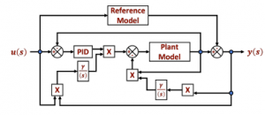
Figure 7: Blocks diagram of the MRAC-PID structure.
Then, Fig. 7 shows the general structure of the implemented controller, where the PID block from the diagram is taken as the classic PID parallel topology, which is represented by Fig. 8.
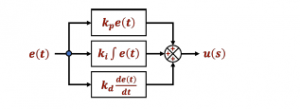
Figure 8: Blocks diagram of the Parallel PID structure.
Henceforth, the PID structure of the controller described by Fig.
8, can be expressed as shown by (8).
where kp, ki and kd are the proportional, integral and derivative gains respectively, and e(t) is the error signal. On the other hand, the reference model described in the blocks diagram from Fig. 7, is taken as a general second order transfer function, which is implemented through the expression defined in (9).
![]()
where, ζ is the dampening ratio of the reference system, which can be delivered through (10).
![]()
where in this case, Mp is taken as the maximum allowed overshoot of the system. Additionally from (9), ωn is the natural frequency of the reference model, which can be defined by
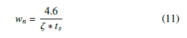
where ts represents the settling time. Moreover, for this application, the settling time is taken as ts = 0.001, with a maximum overshoot Mp = 0.02, where the learning rate for the MRAC is γ = 0.25.
Nevertheless, according to the validation shown in [11], the proposed MRAC-PID controller can be implemented in embedded systems, by using the equations developed in [19], where the constants allow real-time tuning of the controller that learns from the actual behavior of the error. Therefore, the initially implemented equations in the embedded system are:
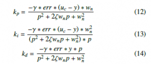
where, err is the normalized error of the system, uc the output of the system, y the reference model output, and p is the slope defined
Consequently, in order to validate the behavior of the controller from which the ANN is going to learn from, Fig. 9 shows the the pendulum using the proposed control topology, which as validated before in [11], it is clear the capabilities of the MRAC-PID to maintain the pendulum in a steady-state in the upright position.
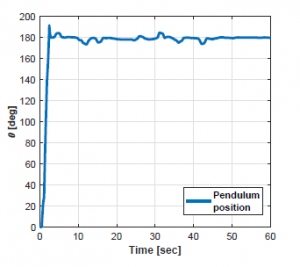
Figure 9: Validation through pendulum’s position against time.
Basically, the Fig. 9 was delivered after sampling a minute of the pendulum’s behavior, using a 50[mSec] sampling rate. In every performed test for this work, the pendulum starts at a 0o initial point (as shown in Fig. 4), and the reference is in the upright position at 180o. Subsequently, with the control objective already fulfilled, the next stage of this work is to take a step into the design based on ANN.
5. Artificial Neural Networks
Artificial Neural Networks (ANN) were first introduced by McCulloch and Pitts in [20] as a propositional logic model that intended to imitate biological neurons. The main objective of their proposal was to use models of artificial neurons, in order to evaluate any logical computation based on AND, OR, and NOT assignments.
Nevertheless, the interconnection of multiple neuron models as seen in Fig. 10, enables to assign different weights at each connection, which allows a better prediction of the training model through the implementation of backpropagation models between them.
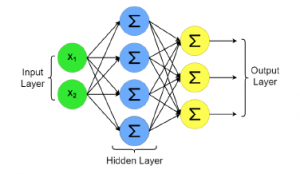
Figure 10: Multiple-layer neuron model
Therefore, knowing that it is possible to use multi-layer neural networks for regression purposes, it can be designed an ANN according to the input-output relationship of the control system (as explained in [21]). Moreover, in the case of a Multiple Input-Single Output (MISO) model, the input layer of the network will assign one neuron to each input, while the final layer will include only one single neuron for the output.
Therefore, regarding the layers of the network, it is commonly used a Rectified Linear Unit (ReLU) function for the hidden layers, which can be described by the expression shown in (15).
![]()
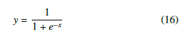
Meanwhile, any linear equation can be used to guarantee positive values; although the selection of the function could vary depending on the nature of the system, for this implementation a Sigmoid given by (16)), was selection for the activation task.
For the regression, the network loss function seeks to minimize the error from the ANN, and can be performed (as explored in [22, 23, 24]) through the mean-squared error (MSE) as given by (17).
![]()
where the estimation of f(x) can be expressed as the product of the input values with the networks weights, as seen in (18).
![]()
Where the optimization objective, is to find the best values for the network weights w, that together with the neurons, brings the behavior of the ANN closer to what is expected; which as explained in [25], can be expressed as shown by (19).
![]()
Subsequently, after presenting the basic elements for the ANN to be designed for the controller of the Furuta Pendulum, the network training will be presented below, based on the data acquired from the experimental testbed.
5.1 MRAC-PID through ANN
The original MRAC-PID controller from [11], implemented in the experimental testbed shown in Fig. 6, was used to generate the dataset of the error measurements obtained during the settling process of the pendulum.
Hence, a total of 11,330 values of the pendulum’s angle error were acquired, which are used as input values for the ANN. Simultaneously, the data from the motor’s duty cycle through time was also acquired, since the duty cycle for the actuator represents the response of the controller (control signal) against the error signal. Thus, output of the network is taken as the control signal for the ANN.
Moreover, the relation between these two variables and their behavior is shown in Fig. 11, where it can be observed that the ideal behavior of the model would be to reduce the duty cycle of the motor when the pendulum is located at 180o.
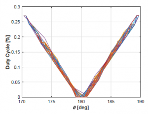
Figure 11: Acquired training data.
Both values (error and duty cycle) were normalized and separated into training, validation, and testing sets, with the 70%, 15%, and 15% relation of the data respectively. The ANN was initialized as described in Table 2, with a MSE loss function and an Adam optimizer with α = 0.0001 inspired by [26].
Table 2: ANN architecture
| Layer | Activation func. | Neurons |
| Input | ReLU | 6 |
| Output | Sigmoid | 1 |
Consequently, the network was trained using 100 epochs with a
128 batch size. After the network was trained, the weight matrix was used to evaluate arbitrary error readings in order to generate the regression function, which later was implemented into the embedded system.
Nevertheless, before the experimental test, the resulting matrix was used in order to evaluate the error in a range between 170o and 190o, which is the operating range for the controller in the testbed, seeking to simulate the the resulting duty cycle that would be programmed into the microcontroller. Therefore, the simulated predictions of the control signal against the error signal are shown in Fig. 12.
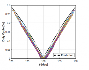
Figure 12: Acquired training data compared to the ANN prediction.
The simulated behavior of the trained network architecture, achieved a similar behavior than the real MRAC-PID controller, with a slightly more aggressive response against the error signal. Which allows predicting a faster response by the ANN-based controller, with a greater performance specially when the pendulum reaches the limit inclination at 170o and 190o.
In addition, the behavior of the predicted results from Fig. 12, demonstrated how the use of an ANN allows more freedom in the system, since the behavior of the net achieves a more regular response of the system, instead of constant changes produced by the modification of the controller coefficients.
Besides, it is clear that in simulation the main advantages of the ANN are not clearly demonstrated, due to the fact that the processing reduction is not evaluated. Thus, it is important to consider and highlight the fact that the obtained prediction, was with simpler arithmetical operations compared to the MRAC-PID controller model; which in a Microcontroller, is traduced into a faster response and into a greater reliability regarding the correct sampling of the error signal, due to the fact that there would be no loss of information or lag in the measurement caused by an improper use of the ticks in the embedded system.
6. Results
The results were achieved through the implementation of the ANN in the embedded system, where one of the main advantages of the proposal is the decrease of the microcontroller’s computational effort, when evaluating real-time samples, due the reduction of computational operators through the the simpler mathematical expressions of the ANN.
In other words, it is faster for the hardware to evaluate just a single matrix operation than the three equations that rule the behavior of the coefficients of the PID controller. Such assumption is observed in Fig. 13 and Fig. 14, where the pendulum’s angle and system’s duty cycle are compared between the original MRAC-PID controller and the ANN model.
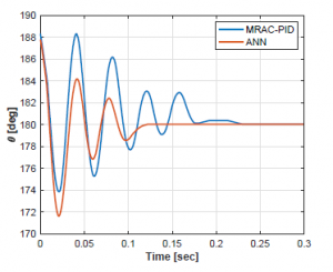
Figure 13: Pendulum’s position through time.
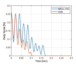
Figure 14: Control signal through time.
Additionally, Fig. 13 shows that the Furuta Pendulum achieves a reduction of the transitional stage, improving the establishment time. As can be clearly seen also in Fig. 13, the controllers were implemented in order to maintain the pendulum in the upright position, therefore the controller begins its operation in the established range (180 ± 10o). Thus, both controllers begin to operate below the 190o for the analysis, stipulated in order to perform fair trails for both controllers.
Therefore, in order to quantify the improvement of the pendulum’s behavior, the error between the reference angle (180o) and the actual angle through time, can be measured by performance indexes as shown in [27] and explored by [28]; from where, Integral of Time multiplied by Squared Error (ITSE) and Integral of time multiplied by Absolute Error (ITAE) were the selected indexes.
The first one, is associated to the error energy it is weighted by time, giving more importance to the most recent errors, and the second one related to the absolute error value in time, giving more importance to the errors in the steady-state. Table 4, summarizes the error indexes obtained after evaluating results from Fig. 13.
Table 3: Error indexes of the controllers.
| MRAC-PID | ANN | |
| ITSE | 2.3942 | 1.4032 |
| ITAE | 0.5381 | 0.3114 |
Hence, by taking the ITSE performance index, the system achieved a 58.61% of error reduction, meanwhile a 57.87% of error reduction was achieved respect to the ITAE index. Then, averaging both results it can be concluded consistently that a 58.24% error reduction was achieved.
On the other hand, last but not the least, Fig. 14 allows to validate the control signal of the controllers, where the [%] of duty cycle through time is shown. Additionally, it can be seen the signal consistency, that is traduced into the reduction of the control effort in time.
The effort reduction can be observed by the way in which the oscillations due to the change in time are compacted, that the ANN controller responds lightly faster than the MRAC-PID, which is enough to allow the faster correction of the pendulum’s angle shown in 13. By integrating the response of the controller through time, in can be quantified the reduction in the control effort, achieving then a 58.69% of control effort reduction from the values summarized in Table 4.
Table 4: Control effort.
| MRAC-PID | ANN |
| 17.8285 | 10.4642 |
Meanwhile, in Fig. 14 it can be analyzed with more detail the settling time improvement, where the system passes from the Ts ≈ 0.17[sec] of the MRAC-PID controller, into the Ts ≈ 0.1[sec] settling time obtained by the proposed solution.
In spite of the consistency of the results, the authors suggest that another possible implementation to evaluate, could be the use of a Recursive Neural Network (RNN) to evaluate the data as a complete sequential variable, instead of evaluating one measurement at a time; however, the RNN case could result in an equal or more complex model than the original PID controller, which could significantly affect the speed in which the controller responds to the error signal.
Nevertheless, the quantified results from the behavior of the controllers in terms of the angle of the pendulum and the controller effort, validated that the proposed controller achieved a better response as expected, due to the faster response of the system and the computational cost reduction.
Finally, it is important to highlight that the duty cycle signal from Fig. 14, it shown in an absolute value due physical limitations. In real applications such as this one, drivers like the MD30C DC motors driver from the designed testbed, receives two control signals: the first one is the PWM whose modulation leads to the amplitude of the control signal, and the second one is the direction for the motor. Therefore, the direction of the pendulum does not depend on the duty cycle, it is defined through the error’s sign.
7. Conclusion
It was observed from the quantification of the results that, not also the behavior of the system followed the original controller’s behavior, but also added a more aggressive response when the pendulum was reaching a limit angle that could result in losing equilibrium.
Additionally, results show how a simple neural network model can be narrowed into a simpler regression model, capable of executing similarly as an original and complex controller; such as the MRAC-PID. Nevertheless, the nature of ANN allowed to achieve the stabilization of the pendulum in the desired state, but through less computational effort from the Microcontroller.
The obtained results showed a 58.61% of error reduction respect to the ITSE, a 57.87% reduction respect the ITAE, and a control effort reduction of 58.69%; those three results remarkably allow to conclude that the implementation of the ANN as substitute for the MRAC-PID controller, achieved a better response for the proposed testbed.
Therefore, this works shows an approach methodology for UMS that could allow to improve other designs, due the faster response of the system and its clear lower computational cost from its mathematical expression. Thus, this work enables the method for simpler implementation or even improvements for existing models through artificial intelligence.
Conflict of Interest
The authors declare no conflict of interest.
Acknowledgment
This research is a product of the Project 266632 “Laboratorio Binacional para la Gestion Inteligente de´ la Sustentabilidad Energetica y la Formaci´ on Tecnol´ ogica” (“Bi-´ National Laboratory on Smart Sustainable Energy Management and Technology Training”), funded by the CONACYT (Consejo Nacional de Ciencia y Tecnologia) SENER (Secretaria de Energia) Fund for Energy Sustainability (Agreement S0019201401).
- Yang Liu and Hongnian Yu. “A survey of underactuated me- chanical systems”. In: IET Control Theory & Applications 7.7 (2013), pp. 921–935.
- JA Acosta. “Furuta’s pendulum: a conservative nonlinear model for theory and practise”. In: Mathematical Problems in Engineering 2010 (2010).
- Karl Johan Åstro¨ m and Katsuhisa Furuta. “Swinging up a pendulum by energy control”. In: Automatica 36.2 (2000), pp. 287–295.
- Navin John Mathew, K Koteswara Rao, and N Sivakumaran. “Swing up and stabilization control of a rotary inverted pendu- lum”. In: IFAC Proceedings Volumes 46.32 (2013), pp. 654– 659.
- Ali Wadi, Jin-Hyuk Lee, and Lotfi Romdhane. “Nonlinear sliding mode control of the Furuta pendulum”. In: 2018 11th International Symposium on Mechatronics and its Applica- tions (ISMA). IEEE. 2018, pp. 1–5.
- Saqib Irfan et al. “Advanced sliding mode control techniques for inverted pendulum: Modelling and simulation”. In: En- gineering science and technology, an international journal 21.4 (2018), pp. 753–759.
- Asif Chalanga, Shyam Kamal, and B Bandyopadhyay. “Con- tinuous integral sliding mode control: A chattering free ap- proach”. In: 2013 IEEE International Symposium on Indus- trial Electronics. IEEE. 2013, pp. 1–6.
- Tamen Thapa Sarkar and Lillie Dewan. “Application of LQR and MRAC for swing up control of Inverted Pendulum”. In: 2017 4th International Conference on Power, Control & Embedded Systems (ICPCES). IEEE. 2017, pp. 1–6.
- Adriana Vargas-Mart´inez and Luis E Garza-Castan˜o´n. “Com- bining adaptive with artificial intelligence and nonlinear meth- ods for fault tolerant control”. In: International Conference on Industrial, Engineering and Other Applications of Applied Intelligent Systems. Springer. 2010, pp. 31–41.
- Efrain Mendez-Flores et al. “Design, Implementation and Nonlinear Control Analysis of a Furuta Pendulum Sys- tem”. In: 2019 4th International Conference on Control and Robotics Engineering (ICCRE). IEEE. 2019, pp. 65–69.
- Seyed Hassan Zabihifar, Arkady Semenovich Yushchenko, and Hamed Navvabi. “Robust control based on adaptive neural network for Rotary inverted pendulum with oscilla- tion compensation”. In: Neural Computing and Applications (2020), pp. 1–13.
- Efrain Mendez et al. “Mobile Phone Usage Detection by ANN Trained with a Metaheuristic Algorithm”. In: Sensors 19.14 (2019), p. 3110.
- Sla´vka Jadlovsky` and Ja´n Sarnovsky`. “Modelling of clas- sical and rotary inverted pendulum systems–a generalized approach”. In: Journal of Electrical Engineering 64.1 (2013), pp. 12–19.
- Daniel Galan et al. “Customized Online Laboratory Exper- iments: A General Tool and Its Application to the Furuta Inverted Pendulum [Focus on Education]”. In: IEEE Control Systems Magazine 39.5 (2019), pp. 75–87.
- Pavol Seman, Martin Juh, Michal Salaj, et al. “Swinging up the Furuta pendulum and its stabilization via model predictive control”. In: journal of Electrical Engineering 64.3 (2013),
pp. 152–158. - Yun Feng Wu, Zhu Ming, and Ke Chang Fu. “Feedforward and Feedback Control of an Inverted Pendulum”. In: Ad- vanced Materials Research. Vol. 328. Trans Tech Publ. 2011, pp. 2194–2197.
- Mayra Antonio-Cruz et al. “Modeling, simulation, and con- struction of a furuta pendulum test-bed”. In: 2015 Interna- tional Conference on Electronics, Communications and Com- puters (CONIELECOMP). IEEE. 2015, pp. 72–79.
- Ai Xiong and Yongkun Fan. “Application of a PID Controller using MRAC Techniques for Control of the DC Electromotor Drive”. In: 2007 International Conference on Mechatronics and Automation. IEEE. 2007, pp. 2616–2621.
- Warren S McCulloch and Walter Pitts. “A logical calculus of the ideas immanent in nervous activity”. In: The bulletin of mathematical biophysics 5.4 (1943), pp. 115–133.
- Aure´lien Ge´ron. Hands-on machine learning with Scikit- Learn and TensorFlow: concepts, tools, and techniques to build intelligent systems. ” O’Reilly Media, Inc.”, 2017.
- Thomas Kailath, Ali H Sayed, and Babak Hassibi. Linear estimation. BOOK. Prentice Hall, 2000.
- Bernard C Levy. Principles of signal detection and parameter estimation. Springer Science & Business Media, 2008.
- Ali H Sayed. Fundamentals of adaptive filtering. John Wiley & Sons, 2003.
- Sun Yuan Kung. Kernel methods and machine learning. Cam- bridge University Press, 2014.
- Diederik P Kingma and Jimmy Ba. “Adam: A method for stochastic optimization”. In: arXiv preprint arXiv:1412.6980 (2014).
- Manuel A Duarte-Mermoud and Rodrigo A Prieto. “Perfor- mance index for quality response of dynamical systems”. In: ISA transactions 43.1 (2004), pp. 133–151.
- E Mendez et al. “Electric machines control optimization by a novel geo-inspired earthquake metaheuristic algorithm”. In: 2018 Nanotechnology for Instrumentation and Measurement (NANOfIM). IEEE. 2018, pp. 1–6.