Controller Design Using Backstepping Algorithm for Fixed-Wing UAV with Thrust Vectoring System

Adv. Sci. Technol. Eng. Syst. J. 5(3), 284–290 (2020);
 DOI: 10.25046/aj050337
This paper describes the design method of a nonlinear flight controller for a fixed-wing UAV with a thrust vectoring system (TVS) using the backstepping method. The flight dynamics of the UAV exhibits strong nonlinear coupling behavior between its translational and rotational motion. The backstepping algorithm has been successfully applied to controller design for such a nonlinear system. However, the main idea of the method is to use some of the state variables as virtual control inputs that need ungeneratable forces by the UAV. To overcome this problem, we use the TVS that can generate thrust in an arbitrary direction. Numerical simulation is performed to confirm the effectiveness of the proposed control method for a fixed-wing UAV with the TVS.
1. Introduction
Unmanned aerial vehicles (UAVs) have been used for national projects, and multirotor are already introduced in various scenes. The fixed-wing UAVs have been used in a specific field [1]. The UAV has some advantages such as high cruising ability or large capacity of payloads. In particular, a small UAV with a wingspan of several meters is superior to a UAV with a wingspan of dozens of meters in maneuverability and maintainability. However, a small UAV has the problem that it is easily affected by the wind disturbance during a flight because of its small moment of inertia. As a result, it is difficult to achieve stable flight of the small UAV when a strong wind blows in a real mission. However, the small UAV cannot avoid an unexpected situation such as a strong wind during a flight because a high-performance device that measures the flight environment cannot be used due to its payload capacity.
One of the ways to solve the problem is to apply a nonlinear control method. The backstepping method [2]–[3], the nonlinear control methods, has also been studied in the fixed-wing UAV flying under the wind disturbance [4]–[7].The advantage of this method is that it makes separated subsystems stabilized by putting the input successively. Therefore, in this study, we attempt to control translational and rotational motion individually to implement the flight at the constant attitude angle under wind disturbance. However, there is a problem that the conventional fixed-wing UAV has a structural restriction that the altitude and the pitch angle cannot be controlled at the same time.
Therefore, we introduce the thrust vectoring system (TVS) for the UAV to solve the problem. The TVS has been used to operate the engine nozzle on aircraft that require maneuverability such as fighter aircraft but also a study on the UAV mounting a propeller-type TVS has been done at late years [8]–[13]. However, in those studies, rather than getting maneuverability as a fighter aircraft, the TVS is mainly used to control the attitude of a tail-sitter UAV during transition flight or the fixed-wing UAV with a broken dynamic surface. In this research, we apply the TVS to the generation of translational force to fly stably under wind disturbance. Finally, we confirm the effectiveness of the proposed method by the numerical simulation.
2. Nonlinear model of UAV
The nonlinear model of UAV can be described separately in translational motion and rotational motion. Control inputs are the thrust vector and the steering angles of an aileron, a rudder, and an elevator. The body coordinate and the inertial coordinate system of UAV are defined as shown in Fig.1.
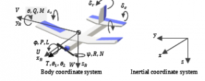
Figure 1: Definition of the coordinate system
2.1. Translational motion
The navigation equation of the UAV is given by
where , , and are the position of the UAV in the inertial coordinate system, its velocity in the body coordinate system, and the Euler angle, respectively. is defined as
Here, c(∙) and s(∙) are abbreviations for the function cos(∙) and the function sin(∙), respectively.
Next, the translational motion equation of UAV is expressed by
![]()
where is the angular velocity of the body coordinate system, and nonlinear matrices , nonlinear vector are defined as
is the aerodynamic force vector, is the control input vector, and is the mass of the UAV. Each element of and is the force along each axis.
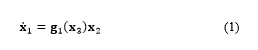
2.2. Rotational motion
The following equation expressed the kinematics equation of the UAV.
Nonlinear matrix is defined as
is the moment of inertia. is the aerodynamic moment vector, and is the control input vector. Each element of and is the moment of the force around each axis.
3. Controller design
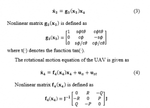
In the backstepping method, the control system is designed considering the stability of each subsystem. In this paper, a control system is designed by putting (1)-(4) as subsystems S1 to S4 ,and its construction is as shown in Fig.2.
Figure 2: The structure of subsystem
In the above figure, control systems are constructed with two extensive subsystems that consist of the translational subsystems (S1, S2) and the rotational subsystems (S3, S4).
3.1. Translational control system
First, in order to give a target value , the position, and velocity for UAV, we define error equation as follows:
![]()
When giving a target value of the velocity, the target value of the position that is the integrated value of the velocity is given instead, assuming the target value of velocity as steady. Then, to introduce a candidate of control Lyapunov function for the subsystem S1, is expressed as
Here, considering state variable as virtual input of S1, and virtual input is defined as . When , the Lyapunov stability theory is satisfied, and becomes a Lyapunov function. i.e., the subsystem S1 gets stable. The following equation can determine the virtual input that satisfies the condition for the system stability because is a regular matrix.
![]()
where is a positive definite and diagonal matrix.
The error equation between state variable and virtual input is as (9).
Then, we define to introduce a candidate as a control Lyapunov function for the whole of the translational systems.
The first term on the right side of (11) is negative-definite according to (8). Therefore, putting the input as written in (12), the second line of the summation of (11) becomes negative-definite that is satisfied, and is determined as Lyapunov function.
where is a positive definite and diagonal matrix.
3.2. Rotational control system
Similar to the previous section, the error equation is defined by using the target value of the Euler angle.
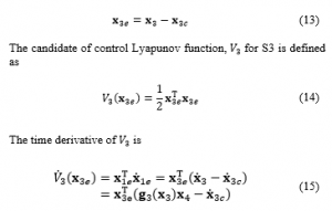
where is a positive definite and diagonal matrix.
The error equation between state variable and virtual input is defined as
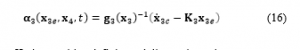
By calculating the input command value to be as the following equation, the second and third lines of the last summation of (19) becomes negative-definite, and it makes the rotational system stable.
![]()
where is a positive definite and diagonal matrix.
Fig.3 Shows the block diagram that includes the controller obtained in sections 3.1 and 3.2.
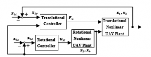
Figure 3: Block diagram of the proposed controller
In this section, we analyze the stability of the entire control system that we designed. The candidate of control Lyapunov function of the entire control system is defined.
3.3. Stability analysis
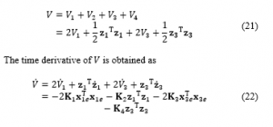
It is clear that the right side in (22) is negative definite because of the coefficient matrix is positive, i.e., the entire system satisfies the Lyapunov stability theory.
3.4. Realization of control input
In section 3.1, we calculated the input command for translational motion. The absolute value of thrust and the target value of the deflection angle are obtained from those commands. The thrust coordinate system is defined as shown in Fig.4.
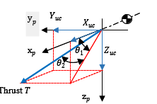
Figure 4: Definition of thrust coordinate system
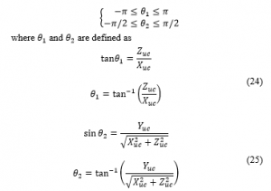
The absolute value of thrust is obtained by (23).
are the commands of the input that is obtained to satisfy the ideal input of .The following inequalities denote the range of angles and .
4. Numerical simulation
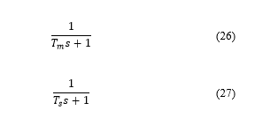
Numerical simulations are conducted to confirm the effect of the TVS on control performance in two cases: the level flight (Case 1) and the improvement of maneuverability by the TVS under the follow-up flight to the target altitude (Case 2) by numerical simulations. The conventional UAV without the TVS, its thrust command is obtained by using only from the translational controller. Moreover, regardless of the presence of the TVS, we introduce the first-order lag filter as written in (26) and (27) to the thrust, the TVS, and dynamic surface. and are the time constants.
Conditions of numerical simulation are shown in Tables 1 to 4.
Table 1: Specification of UAV
| Full length | 0.823 |
| Total height | 0.322 |
| Wingspan | 1.40 |
| MAC | 0.200 |
| Mass m | 0.220 |
Table 2: Initial condition and target value
| Position | |
| Velocity | |
| Euler angle | |
| Angular rate | |
| Target position in Case 1 | |
| Target position in Case 2 | |
| Target velocity |
Table 3: Design control parameters
| Translational controller gain | |
| Translational controller gain | |
| Rotational controller gain | |
| Rotational controller gain |
Table 4: Constraints on control input
| Aileron angle | |
| Elevator angle | |
| Rudder angle | |
| Deflection angle | |
| Deflection angle | |
| Thrust | 0 or more |
| Time constant on thruster | |
| Time constant on dynamic surface and thrust vectoring system |
In addition, the Dryden model [14] is used as a wind disturbance on numerical simulations. The wind disturbance profile is shown in Fig.5.
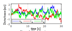
Figure 5: Wind disturbance
Fig.6 to Fig.9 show the numerical results in Case 1. It is clear that the UAV without the TVS cannot keep the altitude as shown in Figs.6(a), 6(b), and 6(d).
Furthermore, it should be noted that the TVS is also effective to control the UAV along y axis as shown in Fig.6(c). One of the main reasons for these flight is that the TVS can generate thrust in arbitrary direction as shown in Fig.8(a) under mechanical constraint. In fact, the inputs for translational motion in Fig.7(a) is constant because the UAV without the TVS cannot generate the thrust for the negative command as shown in Fig.7(b). Fig.7(c) and Fig.8(c) show the attitude angles of the UAV without and with the TVS, respectively. It can be seen from these figures that the TVS suppressed the high-frequency vibration of pitch angle of the UAV. Fig.8(d) shows that the thrust change in Fig.8(a) leads to the sudden change of the elevator deflection to keep the altitude.
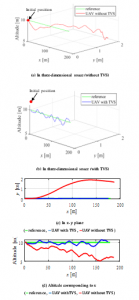
Figure 6: Trajectories of UAV in Case1
Fig.9 shows the phase portrait during the control of the UAV in Case 1. Using the proposed controller, the variables in the phase space follow those references, unlike the controller without the TVS.
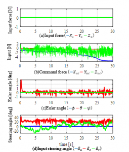
Figure7: Results in case of UAV without TVS (Case1)
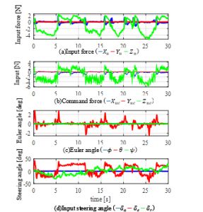
Figure 8: Results in case of UAV with TVS (Case1)
Fig.10 and Fig.11 show the numerical results in Case 2. The altitude of the UAV is controlled from the initial value 10 m to the final value 12 m as shown in Fig. 10(a). In this paper, the final value was decided by 20% higher than the initial value. However, there is no limitation to altitude in the proposed method, but it is necessary to be careful so that the altitude changes slightly. The attitude of the UAV with the TVS in Fig.10(c) is also controlled by control inputs in Fig.10(b) and Fig.10(d) similar to the Case 1. Moreover, it can be seen in Fig.11 that the UAV follows the reference in the phase space.
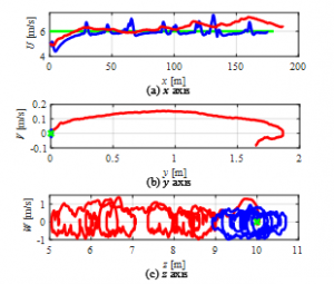
Figure 9: Phase portrait in Case1
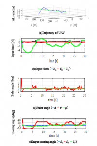
Figure10: Results of the UAV with TVS in Case2
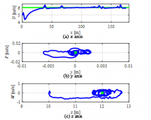
Figure11: Phase portrait in Case2
5. Conclusion
This paper proposed the nonlinear flight control system under disturbance for the UAV with a thrust vectoring system (TVS) using the backstepping method. The results of numerical simulation show that the TVS enables the stable flight even under disturbances for the two cases proposed.
The accurate estimation of the aerodynamic forces would afford the key to succeed the stable flight of the UAV with the TVS. In future work, we will verify the effectiveness of the proposed method experimentally.
- I V Kovalev, A A Voroshilova, and M V Karaseva, “Analysis of the current situation and development trend of the international cargo UAVs market,” J. Phys. Conf. Ser., 1399(5), 055095, 2019.
https://doi.org/10.1088/1742-6596/1399/5/055095 - K. Shimizu, Feedback Control Theory. Corona Publishing Co., 2013.
- M. Krstic, I. Kanellakopoulos, and P. V. Kokotovic, Nonlinear and Adaptive Control Design. Wiley-Interscience, 1995.
- T. Espinoza, A. Dzul, R. Lozano, and P. Parada, “Backstepping — Sliding mode controllers applied to a fixed-wing UAV,” in 2013 International Conference on Unmanned Aircraft Systems (ICUAS), Atlanta, GA, USA, 2013. https://doi.org/10.1109/ICUAS.2013.6564678
- A. Brezoescu, R. Lozano, and P. Castillo, “Bank to turn approach for airplane translational motion in unknown wind,” in 2013 International Conference on Unmanned Aircraft Systems (ICUAS), Atlanta, GA,USA, 2013. https://doi.org/10.1109/ICUAS.2013.6564790
- K. Wu, B. Fan, and X. Zhang, “Trajectory following control of UAVs with wind disturbance,” in 2017 36th Chinese Control Conference (CCC), Dalian, China, 2017. https://doi.org/10.23919/ChiCC.2017.8028144
- A. T. Espinoza Fraire, R. P. Parada Morado, A. E. Dzul López, and R. Lozano Leal, “Design and implementation of fixed-wing MAV controllers,” in 2015 Workshop on Research, Education and Development of Unmanned Aerial Systems (RED-UAS), Cancun, Mexico, 2015. https://doi.org/10.1109/RED-UAS.2015.7441004
- J. W. Roberts, R. Cory, and R. Tedrake, “On the controllability of fixed-wing perching,” in 2009 American Control Conference, St. Louis, MO, USA, 2009. https://doi.org/10.1109/ACC.2009.5160526
- K. Z. Y. Ang et al., “Development of an unmanned tail-sitter with reconfigurable wings: U-Lion,” in 11th IEEE International Conference on Control Automation (ICCA), Taichung, Taiwan, 2014. https://doi.org/10.1109/ICCA.2014.6871015
- C. Liang and C. Cai, “Modeling of a rotor/fixed-wing hybrid unmanned aerial vehicle,” in 2017 36th Chinese Control Conference (CCC), Dalian, China, 2017. https://doi.org/10.23919/ChiCC.2017.8029181
- W. Wang, J. Zhu, M. Kuang, and X. Zhu, “Adaptive Attitude Control for a Tail-Sitter UAV with Single Thrust-Vectored Propeller,” in 2018 IEEE International Conference on Robotics and Automation (ICRA), Brisbane, QLD, Australia, 2018. https://doi.org/10.1109/ICRA.2018.8463158
- M. Kuang, J. Zhu, W. Wang, and Y. Tang, “Flight controller design and demonstration of a thrust-vectored tailsitter,” in 2017 IEEE International Conference on Robotics and Automation (ICRA), Singapore, Singapore, 2017. https://doi.org/10.1109/ICRA.2017.7989605
- H. Kikkawa and K. Uchiyama, “Attitude control of a fixed-wing UAV using thrust vectoring system,” in 2017 Workshop on Research, Education and Development of Unmanned Aerial Systems (RED-UAS), Linkoping, Sweden, 2017. https://doi.org/10.1109/RED-UAS.2017.8101677
- Flying Qualities of Piloted Aircraft. Department of Defense Handbook. MIL-HDBK-1797. Washington, DC: U.S. Department of Defense, 1997.
No related articles were found.