Angular Orientation of Steering Wheel for Differential Drive
 , Deepak Nagalla, Ravi Kiran Pasumarthi, Vamsi Gontu, Phanindra Kumar Allada
Adv. Sci. Technol. Eng. Syst. J. 5(3), 275–283 (2020);
 DOI: 10.25046/aj050336
Several drive mechanisms for different robots are at hand in current days. Bicycle steering, Ackerman steering, differential drive are some principal drive mechanisms that are being deployed in robots these days. The differential drive needs the wheel rotations to be updated very frequently. But it is most commonly deployed on the robots with two wheels and casters, as discussed in this work. It also can be used to have an independent control for each of the wheels with independent control signals. This work deals with the modeling of the differential drive mechanism for a robot with two main drive wheels and two casters, which takes the angular orientation of the steering wheel as input. For simplicity, this work considers that casters have no influence on any aspect of the differential drive. An adaptive model, whose output depends on the real-time input from the gamers steering wheel and produces required output has been formulated. This work differs from the other differential drives in the context that the steering wheel and the robot wheels have no physical connection. The proposed model has been implemented in python and integrated with the Robot Operating System (ROS). The steering wheel, which is used to generate commands using, is attached to the controller at the control station and the ROS_Node thus created is used to read the values from the steering and generate commands for each of the left and right wheels. These commands are transferred to the controller on the mobile platform, which in turn generates control signals for actuators. This work also deals with the deployment of the proposed model using the Universal Robot Description Format (URDF) of the robot in the Gazebo simulation and evaluating it using the Nitho Drive Pro steering wheel. To prove that the differential drive mechanism can be used to control the robot efficiently in any type of terrain, a ROS python node is used to control and maneuver the robot.
1. Introduction
Mobile robots are nowadays being deployed in varied scenarios. Different designs are needed in dissimilar scenarios for effective deployment and efficient use. Each design will be based on a unique drive mechanism [1], which best suits the arena for the implementation of the robot. Some of the most commonly used steering mechanisms are Mecanum drive, Synchronous drive, XR4000, Differential drive and Ackerman steering. Each mechanism has its own not only pros but also cons, which can sometimes be advantageous during installation in the area of interest. Differential drive, which is of interest in this work, works based on the difference in angular velocities of the two wheels of the robot as in work [2]. It has its own disadvantage in requiring the velocities to be updated very frequently. But this mechanism best suits the requirement when the wheels should be operated independently as stated in paper [3]. Especially when the wheels or their alignment is not identical, they should be controlled independently for stability and better control. The robots, though designed based on a drive mechanism, need the control signals to maneuver. These signals can be either autonomously generated or from an HMI device as discussed in paper [4]. Gamer’s steering wheel is one such device which consumes low power and gives an interactive control experience to the user. This can be used to generate the required commands for the differential drive. Unlike implementing this mechanism in cars, most of the robots are wireless and the user cannot be on the robot in all instances. The
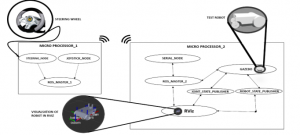
Figure 1(a): Internal ROS communication
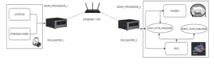
Figure 1(b): Architectural diagram
robot might be at one place and the HMI can be at another. ROS comes handy in such scenarios, especially when data should be exchanged between different nodes, which might be on different systems. ROS acts as a strong platform with a variety of tools and tremendous support for any robotics application. Gazebo, a simulation tool, which is interfaced with ROS as described in the work [5] and can be used to simulate mostly all kinds of robots with simulated arenas, which resemble the real-time environments. And the simulation is plain sailing, a robot or an environment can be built directly in the simulation tool or a URDF file generated from solid works can be used for simulation.
2. Motivation and Problem Statement
Considering the best example for this case is cars with power steering gives an appropriate turn without using much power on the steering. This theory of power steering helps to avoid accidents in vehicles by reducing the effort on the driver and with exact turnings. Inaccurate performance of the vehicle highlights neither the model of the robot nor the working. Many gamers might have used this steering wheel in different PlayStation games in order to get the exact sensation of the game. Comparing this robot with the cars in the games like F1 race, blur and many. Considering the same case in the wheeled robots, implementing this idea may give an appropriate solution. To overcome this problem the following concepts have been proposed. The concept and the modeling [6] in this paper mainly concerned the differential drive with two castor wheels (freewheels) [7], and two main actuators [8]. This model helps the user to control from a remote area where there is no point in direct contact with the robot. The ROS-Gazebo [9] interface with this robot gives the simulation measures that help in achieving accurate results.
3. Related Works
Paper [10] mainly deals with the Varying speeds of differential drive motors and for no of stages. This approach of considering the varying speeds, which is a basic case in any differential drive approach has been adapted. This work deals with a better way of handling highly varying speeds in different scenarios.Kinematic algorithms and mobility control algorithms are explained in [11]. High reliability and precise working mechanisms with powerful dynamic equations can be taken from [12].The system modeling of a four-wheeled differential drive robot which used to achieve accuracy in Control by using sliding mode control is proposed in [13].A hierarchical coordination control approach by defining various layers has been taken from [14].Designing and simulating the robot, using the solid works, nonlinear dynamics to control the simulated robot is presented in [15].The algorithm of the simulation control of robots and the behavior of the robot during simulation is presented in [16]. Working principle of controllers and the new form of feedback to controllers, an easy understanding of the control system is presented in [17]. Designing our own form of the controller and building the interface between the controller and the robot platform is presented in [18]. Wireless communication between the master controller and the slave robots, the algorithm for a wheeled robot is presented in [19]. The differential drive motor control technique has been taken from learning robotics using python as presented in [20]. Paper [21] explains the motion planning of the robot using the differential drive and trajectory smoothing using optimization techniques.Mathematical modeling and behavior of the robot are explained using the skid steering model, the tracking of the robot is also mentioned in paper [22].
4. Architectural Diagram
Figure 1(a) shows the ROS connections and communications of the entire system and how it controls the robot from a control station to the remote position of the robot. The left block in the diagram i.e. with the steering wheel explains the internal process happening at the control station. Similarly, the right block explains the internal connections and the processes happening within the robot. Figure 1(b) shows the architectural block diagram of this robot.
4.1. ROS_Master_1
The master controller of the MICRO_PROCESSOR_1 is entirely dependent on the ROS_MASTER_1 node which is independent of the entire package once the roscore is launched it automatically starts. Once the ROS_MASTER_1 is activated it acts as a host and starts connecting to different nodes (or vice versa) with different topics as a bridge and communicating among themselves. This node runs in the control station and communicates within the nodes i.e.; STEERING_NODE and JOYSTICK_NODE.
4.2. Steering_Node
The input to the ROS_MASTER_1 is given from either keyboard or steering wheel, which is connected to the processor through I/O peripherals. Keys like ‘i’, ‘,’, ‘j’, ‘l’ in the keyboard are used for the movement of the robot in forward, backward, right, left respectively. Speed control can also be done using the keyboard. The steering wheel can be used for the same and the control resembles driving a car. These devices’ steering wheel, joystick should be integrated and accessed with the ROS_MASTER_1 through STEERING_NODE and JOYSTICK_NODE.
4.3. Joystick_Node:
These nodes form a bridge between I/O devices and ROS. Each key of these devices has a unique ID in these nodes. So, when a key is pressed, the respective ID gets active and this, in turn, can be assigned with a function to be performed. The values or commands generated in this function are published over a topic that can be accessed by the Gazebo node, where the robot is being simulated in different environments.
4.4. ROS_Master_2
Microcontroller_2 has another ROSmaster named ROS_MASTER_2 which is in the mobile robot that communicates with the nodes at the remote area i.e. within the robot. Since the entire communication of the system is done through wireless connectivity, both the ROS_MASTER’s are controlled using the master-slave protocol.
4.5. Gazebo
The gazebo is open-source for the simulation of different environments. Gazebo interfaces with ROS and communication are done using the GAZEBO node. It can act as a publisher as well as a subscriber. GAZEBO node subscribes to the commands published by the STEERING_NODE and JOYSTICK_NODE to move the joints of the robot accordingly. It also publishes the transforms of the URDF node which in turn helps to move the robot. The Joint_states of the robot’s movement is published (JOINT_STATE_PUBLISHER)over the Odom topic which is used by the differential drive plugin to correct the robot’s path from the intended path. This data is also used by RViz to mimic the robot in Gazebo.
4.6. Joint_State_Publisher
This is used to read data from various origins. This has special features such as inputting the values through the graphical user interface, sending those values to the other joint and can set the default values even. It includes various parameters such as robot description, velocities, position, dependent joints…etc.
4.7. Robot_State_Publisher
ROBOT_STATE_PUBLISHER is used to publish the state of the robot to a tool where it can keep track of multiple coordinate frames per overtime. For a package, the position of the joint is taken as the initial values. This package subscribes to the joint states of the robot and publishes a three-dimensional representation of each and every link using the kinematic involved in the URDF model. Internally it has a kinematic model of the robot. General parameters used by this node are robot description, tf_prefix, publish frequency and it subscribes to the node joint states.
4.8. RViz
RViz is a platform for visualization and displaying different sensor values and information using ROS. It helps us to analyze different aspects of the robot-like transforms.
Transforms play a dominant role in avoiding collisions and in establishing coordination amongst the different frames and regulating the movement of all the joints. Not just the transforms of physical systems but also with the odometry frame can be calculated. This is not a simulation tool but a visualization interface where we can visualize both simulated robots and a real-time robot as shown in Figure 2.
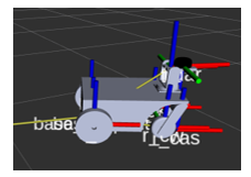
Figure 2: Robot model in RViz with TF’s
4.9. Serial_Node
SERIAL_NODE introduces serial communication which is a bit to bit transmission of data. Rosserial helps this type of communication in different hardware parts of microcontrollers such as Arduino, teensy and also acts as an interface between the hardware devices and software tools.
5. Design and implementation
5.1. Implementation in a software platform
Nodes are a part of ROS in which they communicate with the other nodes in order to transfer the data or information. These nodes are generally connected by a bridge called a topic. The topic is a unidirectional data channel. The communication between these nodes and topics can be viewed through graphs(Rqt_graph) or frames.
The simulator consists of launch and configuration files. A virtual robot can be built in Gazebo which produces a xacro file that has all the links connected to the parent link. Similar to the Gazebo tool we have many other platforms (v-rep, webots, solid works) in which Solid works are most prominent for designing.
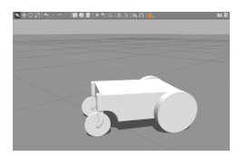
Figure 3: Gazebo Bot
Solid works to URDF exporter has been used to generate a URDF file from the solid works model, which includes inertia on the body, torque on the wheel links, parent links, velocity as shown in Figure 3. For the obtained URDF file adding the differential-drive [23] motor controls the velocity of the wheels independently. Forward kinematics equations are used in differential-drive to solve the problems obtained during the slippery surfaces controlling velocity.
![]()
where V is the velocity of the wheel, r is the radius of the wheel, is the angular velocity of the wheel.
This above Equation (1) is the basic fundamental for this differential-drive. This URDF file is added into a ROS package and connected to the master and we can navigate the robot in any environment. Once the body is computationally ready with all the connections within the code, the controller launches all the required files using ROS commands. These launch files communicate through the nodes to publish or access the required data. The topic of Joint_states published by the Gazebo node and subscribed to the keyboard node using the command velocity(/cmd_vel) topic.
5.2. Steering wheel control
Nitho Drive Pro is a Steering wheel compatible with PC2, PC3 and PC. It helps us to control the Wheeled robot using teleoperation. In the steering wheel, the Joint_state_values are published in the terminal, which is in turn subscribed by the robot, which helps in teleoperation. This robot simulation helps us to get the virtual feedback in Gazebo, so the operator knows what is happening just by looking in the simulation. By using the steering wheel, we can even adjust the speed and also the direction we want to turn using axis values. We can assign different values for buttons ranging from 0 to 1. We can change the values of the axes to turn based on our needs. The Steering Wheel system consists of two different controls for the forward and backward motion. One is pedal motion and the other is by using the buttons on the steering wheel.
This Steering wheel system can be implemented in an actual car driving for handicapped people who cannot apply much force to turn the wheel. Nitho Drive Pro does not require much force to rotate its wheel and it can be programmed in such a way that we can increase or decrease the speed by pressing the designated buttons. We can also find out which buttons are assigned for what number and its functions. By giving the command we can access the control system of the steering wheel and find out the mapping of the steering wheel and be able to change the calibration of the steering wheel. In the mapping option of the steering wheel, we can find out which button is assigned to which number and helps to change the controls accordingly. In calibration default values are assigned to the buttons and axes for movement, we can change the calibration values manually or by altering the values. We can even change the mode of controlling the axes. If the PS/MODE button is on it means that the steering wheel gives the continuous values of the axes, else if it is in the steady mode it means that the axes are in button state, it behaves just like a button and gives a single value. If it is off that means that the steering wheel is off.
5.3. Four-wheeled Differential drive
For the design of a Two-wheeled differential drive model initially, a Four-Wheeled drive model is discussed. This drive system is mainly composed of control and drive systems. The mechanical structure is the basis for the entire robot. It turns using all the four wheels, unlike normal vehicles. Each wheel has a separate motor mechanism to drive the steering of the wheel. Therefore, the motion of all the wheels of the robot are independent of each other.
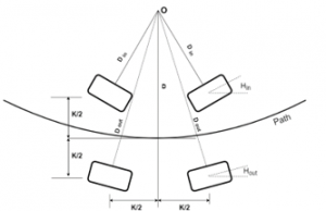
Figure 4: four-wheeled differential drive robot.
From geometric relation, from (Figure 4) it can be considered as follows
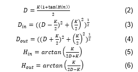
Where D is the radius of the body in which it rotates, Din is the radius of inner wheels in which it rotates, Dout is the radius of outer wheels in which it rotates, K is the separation between left and right wheels/separation between front and back wheel, is the slip angle of outer wheels, Hin is the slip angle of inner wheels. The speed relationship is as follows:
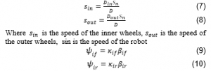
where i=L refers left, i=R refers right. and denote the lateral force of front wheels and rear wheels respectively. and are the lateral stiffness of the front wheels and rear wheels respectively. is the slip angle for front wheels and is the slip angle for rear wheels.
5.4. Implementation of a two-wheeled robot
Implementing a robot with a simple 2 wheeled mechanism which has a common axis of rotation. And two caster wheels in the front so there will be no slip angle for the wheels. There will be only one inner wheel and one outer wheel. The moment of the body in circular turns are modeled by the varying speeds of the two wheels. from (Figure 6) the geometric relations of the two-wheeled robots are as follows.
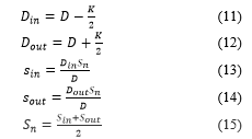
where D is the radius of the body in which it rotates, is the radius of inner wheels in which it rotates, is the radius of outer wheels in which it rotates, K is the separation between left and right wheels/separation between front and back wheels, is the speed of the inner wheels, is the speed of the outer wheels, is the speed of the robot.
Varying Speeds of front and back motors in terms of rotations per minute.
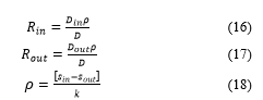
where is the speed of the inner wheel (RpM), is the angular velocity of the robot.
The D (Radius of robot rotation) value will be defined by the steering control as shown in the following graph.
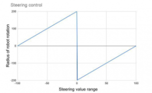
Figure 5: The varying values of D (Radius of robot rotation) according to the steering control (steering readings).
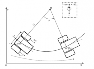
Figure 6: The transformation of the body in a 2D frame.
The robot started at M’ at time t=0, the coordinates of the robot at time t= . is M’’ the transformation equations are:
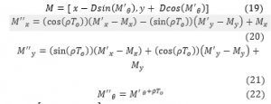
where are the coordinates of robot and angle of orientation at M’, are the coordinates of robot and angle of orientation at M’, are the coordinates of the virtual center of rotation M
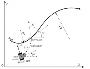
Figure 7: Tracking of the robot according to the steering control values.
The robot is at a random position [X1, Y1, Q1], in order to follow the path on which it should follow it should first align with the path along the aligning path which is mentioned in Figure 7. The aligning path of radius ‘r’ which meets at a point on the path to be followed after z1 degrees of rotation. The robot now should rotate the z2 angle for making it tangential to the path and follow the path with the radius R2. This path can be tracked in the simulation when controlled using the steering wheel. The following equations give the position of the robot at a time . obtained from the transformation equations.
6. Experiments
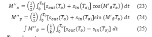
To get the real experience of controlling a robot, the Nitho Pro drive steering wheel has been used as shown in Figure 8, to control the robot which is compatible with any type of system. The robot is controlled in Gazebo to get a clear idea of real-life scenarios. Using the differential drive plugin, the angle of rotation of the robot is adjusted to the turning ratio of the steering wheel to get a better idea of the testing scenario and for easy control of the robot as mentioned in [6]. For the controlling of the robot in multiple scenarios using Gazebo, a directory was created. This directory was used to control the robot using a keyboard. After successfully controlling using the keyboard a directory to control using the Steering wheel has been created.
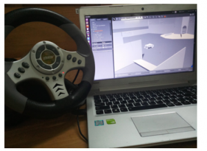
Figure 8: Steering Wheel Control
Control of the robot using the Steering wheel in gazebo has been successfully implemented using ROS. Differential drive plugin has been added to the URDF file for the control of the robot. The robot has been tested on multiple terrains to test the control and manoeuvrability in different conditions. It was designed in such a way that the speed and angle of rotation of the robot can be monitored from (1), (2) and (3). If the power is kept constant the forces acting on the robot will differ due to the terrain conditions, stiffness, slipping and other forces acting in the body as shown in (9) and (10).
Figure 9: A. Plane surface, B. Asphalt Plane, C. Rough surface, D. Grass field
Multiple testing scenarios were considered for the implementation of the robot model. For the case of flat surfaces in Figure 9.A-D, is considered in many daily life scenarios. Figure A. is a Plane smooth surface where frictional value is zero which cannot be found in our daily life. When the robot is given even a small amount of speed the body moves freely as there is no opposing force but for cases such as Figure 9.B-D, which can be found in our daily a certain amount of force needs to be applied to overcome the frictional force and start moving. In the case of grass fields, the body moves freely due to less frictional force and covers a certain distance in less amount of time as shown in Table.
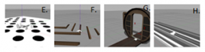
Figure 10: E. Crater surface, F. Uneven path, G. Doorway, H. Moat plane
In the case of scenarios such as rough surfaces in Figure 10..E-H., more speed is required to move over the obstacles but as the power is kept constant the robot moves at a slower speed compared to the plane surface and as a result, it takes more time. For the crater surface, maneuverability and angle of rotation are important to avoid the craters and advance smoothly. Whereas for the case of other rough surfaces in Figure 10.F-H., speed is required to avoid the obstacles or move over them.
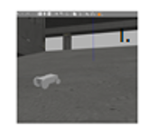
Figure 11: I. Slope
In the case of the plane slope in Figure 11.I, more speed should be provided than in the case of a plane surface as the robot needs to go to a higher place carrying its entire weight as the frictional force is acting in the opposite direction while moving up and in the direction of motion while coming down. But if the speed is given above a certain value the robot topples and if we rotate the body at high speed it topples.
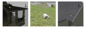
Figure 12: J. Collapsed roof, K. Slippery Slope, L. Rough slope
In the case of the collapsed roof in Figure 12.J, and the rough slope in Figure 12.L, the body does not move easily as there is a frictional force between the surface and the robot compared to the case of plane slope and as a result, the body does not topple easily. But, for the case of driving terrain in Figure 12.K, the surface is damp and the robot slips and drifts while moving with more than the required speed but when given an appropriate speed the robot moves smoothly without sliding as the inclination of the plane is not constant.
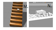
Figure 13: M. Steps, N. Uneven Path
Stairs are also a type of terrain but with both inclination and rough surface as shown in Figure 13.M, where control and mobility play an important part in the manoeuvrability of the robot. The uneven path in Figure 13.N is like rough paths in Figure 10.F-H, which requires more speed and mobility to avoid getting stuck in between the obstacles.
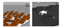
Figure 14: O. Teeter Ramps, P. Ramps
For testing the mobility and stability of the robot teeter ramps are chosen as shown in Figure 14.O The robot should move from one ramp to another while balancing the weight and move steadily over the ramps. Similarly, ramps were placed in Figure 15.P, to test the maneuverability of the robot to avoid obstacles and move smoothly over the ramps.
7. Results
The below Table provides the details of the frequencies at which the data is being published on different topics in different terrains and time taken for the robot to complete the first half of the distance as T1(sec) and the other half as T2(sec). From which we can infer that even in different scenarios the rate at which the data is being published is the same and the change in the behavior is mainly due to the speed and control, which affects the time taken by the robot to travel a certain distance.
Table 1: Frequencies of different Topics are published in multiple terrains
| Test surface | Joy_ topic |
Cmd_vel | Joint_states | Tf | Time
(T1) |
Time
(T2) |
| A | 24.42 | 24.86 | 9.97 | 54.87 | 10 | 10 |
| B | 24.14 | 24.94 | 9.98 | 55.0 | 11.8 | 11.8 |
| C | 24.33 | 24.92 | 9.92 | 55.04 | 12.4 | 12.4 |
| D | 24.01 | 24.66 | 9.96 | 54.99 | 10.7 | 10.7 |
| E | 24.23 | 24.53 | 10.0 | 54.88 | 11.2 | 11.2 |
| F | 24.46 | 24.79 | 9.98 | 55.09 | 13.6 | 13.6 |
| G | 24.39 | 24.35 | 9.96 | 54.89 | 14 | 14 |
| H | 24.19 | 24.95 | 9.99 | 54.93 | 19.6 | 19.5 |
| I | 24.53 | 24.92 | 10.0 | 54.91 | 12.2 | 7.93 |
| J | 24.36 | 24.61 | 9.97 | 54.99 | 14.7 | 11.9 |
| K | 24.29 | 24.42 | 9.99 | 54.89 | 13.2 | 9.1 |
| L | 24.12 | 24.84 | 10.0 | 55.02 | 15.6 | 12.3 |
| M | 24.24 | 24.18 | 9.92 | 54.9 | – | 10.8 |
| N | 24.2 | 24.4 | 10.0 | 55.01 | 16.2 | 17.5 |
| O | 24.18 | 24.49 | 9.76 | 54.96 | 15.3 | 15.7 |
| P | 24.09 | 24.26 | 10.0 | 54.88 | 17.4 | 16.9 |
While rotating the body the amount of speed required and the angle of rotation differs for different surfaces. When the body is moving in a straight line, the center point of rotation lies at an infinite distance from the robot. Similarly, when the angle of rotation of the robot increases the center point of rotation decreases until it approaches the center of the robot which works on the same principle of a differential drive plugin. When the angle of rotation for the robot is maximum the robot rotates at its own position as a center. When the angle of rotation increases the center point of rotation moves away from the robot and it occupies more space to rotate. As the outer wheel is at a larger distance from the center point of rotation the outer wheel covers more distance compared to the inner rotating wheel. This shows that angular orientation also plays a major role in the movement of the robot. Under normal circumstances, it might take a while to turn or control the robot in different conditions but using differential drive mechanism we can maneuver the robot easily through any type of terrains.
8. Conclusion
The major focus of this work is to model the differential drive for a wheeled robot. The mathematical equations have been derived for a robot with two caster wheels and two main drive wheels, by assuming that the casters are ideal and will not affect the drive in any form. The proposed model has been implemented using python and the file has been successfully converted to a ROS node for integrating it with ROS. The model has been evaluated using the simulation tools. A URDF file of the robot model has been generated from SolidWorks (SW) using SW to URDF exporter plugin and this has been triumphantly launched in the Gazebo platform and integrated with the node generated previously. The hardware integration of the steering wheel with the Gazebo environment has also been achieved. All the works referred to in this work are either dealing with the modeling of different aspects of different drive mechanisms or the ROS aspect of the robots, controllers, control systems. All the previous works referred to in this work discuss the usage of joysticks or have steering on the robot. As stated earlier, the major difference of this work is that the steering wheel and the robot are different entities. They do not have any physical contact. But virtually it is similar to having the steering physically on the robot. The ROS node takes care of the exchange of control information between these two entities. The robot has been tested in different environments and different readings from ROS have been collected to evaluate the performance, which shows a steady performance of the published velocity values and stable performance of the robot.
8.1. Future work
Gazebo simulation and RViz visualization with two-wheeled differential drive vehicle integrating with mapping modules and some sensors make the robot autonomous and increase the performance and efficiency of the robot. To implement and evaluate these applications on the real-time heavy-duty robot in the future plan. Improvising the performance of the robot by optimizing the algorithms which can reduce the delay in the response. Evaluating the performance of the heavy-duty may lead to further improvement of the robot. Optimizing the robot with high profile sensor components will get accurate and precise results.
Acknowledgment
Firstly, we would like to thank our institute Amrita Vishwa Vidyapeetham for providing the laboratory and components. The editors of HuTLabs and its staff have supported this work in each and every point of time and the people from the department of electronics and communication engineering have been constant supporters for the project at any point. Finally, we’d like to thank all the authors, maintainers and all the ROS users who worked and helped for the project with great positivity, composure, and determination.
- R. K. Megalingam, D. Nagalla, R. K. Pasumarthi, V. Gontu, and P. K. Allada, “ROS Based, Simulation and Control of a Wheeled Robot using Gamer’s Steering Wheel, “2018 4th International Conference on Computing Communication and Automation (ICCCA), Greater Noida, India, 2018 DOI:10.1109/CCAA.2018.8777569
- Wei Yu, Oscar Ylaya Chuy, Jr., Emmanuel G. Collins, Jr., Patrick Hollis, “ Analysis and Experimental Verification for Dynamic Modeling of a Skid-Steered Wheeled Vehicle”, IEEE Transactions on Robotics., vol. 26, pp. 340-353, Mar. 2010. DOI: 10.1109/TRO.2010.2042540
- Li Wang, Xinhui Liu, Xin Wang, Beibei Fu, Ran Xu, “ Research on differential performance of four-wheel independent steering of a hydraulic wheel-driving off-road vehicle”, The Journal of Engineering., vol. 2019, pp. 68-73, May. 2019. DOI:10.1049/joe.2018.8956
- Nobutake Hiraoka, Katsuhiko Inagaki, “A study of a new controller interface for omnidirectional robots”, 10th Asian Control Conference (ASCC), 2015. DOI: 10.1109/ASCC.2015.7244592
- Xudong Ma Fang Fang; Kun Qian; Can Liang, “Networked robot systems for indoor service enhanced via ROS middleware”, 2018 13th IEEE Conference on Industrial Electronics and Applications (ICIEA), 2018.DOI: 10.1109/ICIEA.2018.8397832
- Rajesh Kannan Megalingam; Sricharan Boddupalli; K. G. S. Apuroop, “Robotic arm control through mimicking of miniature robotic arm”, 2017 4th International Conference on Advanced Computing and Communication Systems (ICACCS), 2017. DOI:10.1109/ICACCS.2017.8014622
- Jianfeng Liao, Zheng Chen, Bin Yao, “ Performance-Oriented Coordinated Adaptive Robust Control for Four-Wheel Independently Driven Skid Steer Mobile Robot”, IEEE Access., vol. 5, pp. 19048-19057, Sept. 2017. DOI: 10.1109/ACCESS.2017.2754647
- Jianfeng Liao, Zheng Chen, Bin Yao, “ Model-Based Coordinated Control of Four-Wheel Independently Driven Skid Steer Mobile Robot with Wheel-Ground Interaction and Wheel Dynamics.”, IEEE Transactions on Industrial Informatics., vol. 15, pp. 1742-1752, Sept. 2018. DOI10.1109/TII.2018.2869573
- Masayoshi Wada, “A Joystick Steering Control System with Variable Sensitivity For Stable High Speed Driving”, IECON 2013 – 39th Annual Conference of the IEEE Industrial Electronics Society, 2013. DOI: 10.1109/IECON.2013.6699781
- F.U. Rehman, M.M. Ahmed, “ Steering Control Algorithm for a class of wheeled mobile robots”, IET Control Theory and Applications., vol. 1, pp. 915-924, Jul. 2007. DOI: 10.1049/iet-cta:20060189
- M.A. Minor, B.W. Albiston, C.L. Schwensen, “ Simplified Control of a two-axle compliant framed wheeled mobile robot”, IEEE Transactions on Robotics, vol. 22, pp. 491-506, Jun. 2006. DOI: 10.1109/TRO.2006.875503
- Jingang Yi, Hongpeng Wang, Junjie Zhang, Dezhen Song, Suhada Jayasuriya, Jingtai Liu, “ Kinematic Modeling and Analysis of Skid-Steered Mobile Robots with Applications to Low-Cost Inertial-Measurement -Unit-Based Motion Estimation”, IEEE Transactions and Robotics., vol 25, pp. 1087-1097, Jul. 2009. DOI: 10.1109/ROBOT.2009.5152342
- Wei Shen, Zhichun Pan, Min Li, Hui Peng, “ A Lateral control method for Wheeled-Footed Robot based on Sliding mode control and Steering Prediction”, IEEE Access., vol. 6, pp. 58086-58095, Oct. 2018. DOI: 10.1109/ACCESS.2018.2873020
- Junnian Wang, Zheng Luo, Yan Wang, Bin Yang, Francis Assadian, “ Coordinated Control of Differential Drive Assist Steering and Vehicle Stability Control for Four-Wheel-Independent-Drive EV”, IEEE Transactions on Vehicular Technology., vol. 67, pp. 11453-11467, Oct. 2018. DOI 10.1109/TVT.2018.2872857
- Yousuf, L.S.Email Author,” Experimental and simulation investigation of nonlinear dynamic behavior of a polydyne cam and roller follower mechanism”, Mechanical Systems and Signal Processing 116, pp. 293-309, 2018. DOI: 10.1016/j.ymssp.2018.06.028
- Altarazi, S.A. Ammouri, M.M.,” Concurrent manual-order-picking warehouse design: a simulation-based design of experiments approach”, International Journal of Production Research pp. 1-19, 2017. DOI: 10.1080/00207543.2017.1421780
- Ashley L. Guinan; Nathaniel A. Caswell; Frank A. Drews, “William R. ProvancherA video game controller with skin stretch haptic feedback,” 2013 IEEE International Conference on Consumer Electronics (ICCE), 2013. DOI: 10.1109/ICCE.2013.6486973
- Rajesh Kannan Megalingam; Sarath Sreekanth; Govardhan; Chinta Ravi Teja; Akhil Raj, “Wireless gesture controlled wheelchair”, 2017 4th International Conference on Advanced Computing and Communication Systems (ICACCS), 2017. DOI: 10.1109/ICACCS.2017.8014621
- Rajesh Kannan Megalingam; Deepak Nagalla; Pasumarthi Ravi Kiran; Ravi Teja Geesala; Katta Nigam, “Swarm based autonomous landmine detecting robots”, 2017 International Conference on Inventive Computing and Informatics (ICICI), 2017. DOI: 10.1109/ICICI.2017.8365205
- Lentin Joseph, “learning Robotics using Python, Packt Publishing, 2015.
- W. Huang, X. Wu, Q. Zhang, N. Wu, and Z. Song, “Trajectory optimization of autonomous driving by differential dynamic programming,” 2014 13th International Conference on Control Automation Robotics & Vision (ICARCV), Singapore, 2014 DOI: 10.1109/ICARCV.2014.7064582
- Y. Wu et al., “Experimental kinematics modeling estimation for wheeled skid-steering mobile robots,” 2013 IEEE International Conference on Robotics and Biomimetics (ROBIO), Shenzhen, 2013 DOI: 10.1109/ROBIO.2013.6739470
- El-Dessoky, M.M, Alzahrani, E.O, Almohammadi, N.A, “Chaos control and function projective synchronization of novel chaotic dynamical system”, Journal of Computational Analysis and Applications 27(1), pp. 162-172, 2018. DOI: 10.1155/2011/452671