
Piezoelectric Teeth Aligners to Accelerate Orthodontics Treatment
Volume 5, Issue 3, Page No 178-190, 2020
Author’s Name: Muath Bani-Hani1,a), M. Amin Karami2
View Affiliations
1Department of Aeronautical Engineering, Jordan University of Science and Technology, Irbid, Jordan
2Department of Mechanical and Aerospace Engineering, The State University of New York at Buffalo, 14260, U.S.A
a)Author to whom correspondence should be addressed. E-mail: Mabanihani@just.edu.jo
Adv. Sci. Technol. Eng. Syst. J. 5(3), 178-190 (2020); ![]() DOI: 10.25046/aj050324
DOI: 10.25046/aj050324
Keywords: Biomedical materials, Piezoelectric actuators, Orthotics & patient treatment

Export Citations
In this paper, we are proposing a device that generates vibration to possibly reduce the duration required for the orthodontic treatment by enhancing the tooth movement. This is achieved by harmonically exciting a bio-compatible material, namely polyvinylidene fluoride (PVDF) to generate vibration and consequently a cyclic force at a low frequency of 30 Hz. (PVDF) is a very common piezoelectric polymer due to the high elasticity it can provide, biocompatibility, and its low cost compared to other piezoelectric materials. Applying a cyclic loading (vibration) in general will reverse bone loss, stimulate bone mass, induce cranial growth, and consequently accelerate tooth movement. This has a major effect on the patient’s treatment experience by reducing the associated pain and discomfort throughout the treatment process and hence improves the patient’s compliance with the treatment with negligible side effects compared to therapeutic treatments. The proposed device is fitted to a positioner or tooth aligner. The proposed device can accommodate a voltage harmonic function generator, a casing to house the battery and the micro-processor. Modern methods require a bulky and extra-oral device that is quite cumbrous to the patient. In this paper, an analytical model based on the distributed parameter approach is employed. Finite Element Analysis (FEM) is also employed to study and analyze the Piezoelectric actuation behavior.
Received: 13 April 2019, Accepted: 28 August 2019, Published Online: 15 May 2020
1. Introduction
The work presented in this paper is an extension of what was presented in 2018 40th Annual International Conference of the IEEE Engineering in Medicine and Biology Society (EMBC) [1].
Orthodontics is a dental domain that deals with enhancing the movement of teeth to treat malocclusion. This mainly deals with the correction of malposition of the teeth and the jaws. Malocclusion suggests that the upper and lower jaws are not in complete alignment for biting or chewing which leads to uneven bite, cross bite, or overbite. Therefore, this might negatively affect a person’s physical appeal, communication and eating capabilities.
Malocclusion is traditionally adjusted through a steady/constant mechanically applied force to encourage bone modelling, which enhance the teeth movement to a preferred position. For this method, an orthodontic device applies a constant and stagnant force on the teeth through a bent wire attached to brackets fixed on the teeth or an aligner. This continuous force is slowly dissipated as the teeth move into position. The wires or the retainer are tweaked accordingly to ensure the teeth move to the optimal position.
Swartz [2] shows the optimum force to move a tooth is just enough to overcome blood vessels pressure (20-26 grams/cm2). Any extra force used to move a tooth can significantly affect blood circulation, leading to root resorption. In this method, as known as fixed orthodontic treatment, 2 to 3 years are required for the completion of the treatment [3, 4]. It also poses a high risk of caries [5, 6], root resorption [7, 8], and reduce patient compliance over time [9]. Multiple studies have found a certain connection between extended treatment and the root resorption experienced by a patient [7, 10, 11]. However, even when no radiographic signs of root resorption can be visible, it is acceptable that most teeth undergoing orthodontic tooth movement will experience some degree of root resorption followed by repair [12]. The first person to reveal a radiographic proof of root resorption amid an orthodontic treatment was Ketchum [13]. He found that out of five hundred patients, 21% were found to have root resorption. For this reason, it is imperative to study the acceleration of tooth movement to reduce treatment duration time. Several methods to accelerate teeth movement have been studied, including laser therapy [14, 15], pulsating electromagnetic fields [16], electrical currents [17], corticotomy [18, 19], distraction osteogenesis, [20-22] and mechanical vibration [23].
Rubin et al 2001 revealed that the use of low amplitude mechanically vibrating forces/pulses at a high frequency could help in stimulating bone growth. This type of therapy, also referred to as vibration therapy, has been used to improve or maintain bone and muscle mass in rehabilitation of mobility impaired patients [24]. It has been also utilized to combat decreased bone density [25, 26] and improving post-surgical healing [27, 28]. During his animal studies, Rubin found out that bone density in the proximal femur showed a 43% increase after sessions of 20 minutes/day of high frequency (30Hz) and low amplitude force (0.3g) [29-31].
The small strains generated by high frequency mechanical vibrations are implemented to speed up periodontal and bone tissue remodeling through speeding up tooth movement. With the minimal side effects, this method of orthodontic treatment has the advantage over the current medicinal treatments. It is also a safer alternative for enhancing bone remodeling in the medical field [32, 33].
Researchers have suggested that a pulsating could possibly move teeth faster with less discomfort associated with the traditional orthodontics. Nishimura and Chiba M in 2008 [23], used intermittent stimulation of the periodontal tissue by resonance mechanical vibration to accelerate experimental tooth movement in rats. His study was performed on a sample of 42 wistar rats with an experimental duration of 21 days. It was shown a major speed up in the rate of the tooth malocclusion treatment in comparison to non-vibration control sample. Nevertheless, Mao was the pioneer in his field to actually prove that the use of pulsating/cyclic forces compared to static loading, could significantly improve dental straightening in rabbits [34].
Currently, a wide range of teeth vibration devices are available and used in orthodontic treatment. Craven H. Hurz [35] uses a hefty exterior power source that supplies electricity to one to four small motors. His device [36, 37] is modified to use pulsating fluids that are produced due to the chewing motion of a jaw. A radio device is also included that oscillates in response to a radio wave and generates a pulsating/vibrating force on the teeth. The devices are fitted to a headband and attached to the teeth by its intraoral components. This configuration made the device complex, expensive to build, and made it uncomfortable for the patient to wear.
In 1991, Branford [38] proposed a hand-held device used to potentially treat the periodontal disease. It used a mouth-piece made of malleable dental brass adjustable to the patient’s bite and an external vibrator to induce oscillations in the teeth. However, this device required an external power source to power the vibrations.
Michael J. Powers [39] also proposed a hand-held tooth vibrator in 1999. Power’s device employed a motor linked to a vibrating intraoral mouthpiece. The drawback to his proposed device was user discomfort due to increased blood flow from the vibrations. The bulkiness of the power actuator also affected user comfort and patient compliance, as defined by John C. Voudouris in 2001 [40]. The device is mounted on brackets which reduce the effectiveness of conveying the vibration forces to the teeth. Matsushita Electric Works, Ltd. [41] created a multipart intraoral pulsating device, intended to be attached or fitted over the lower and upper teeth to apply vibrating/pulsating forces. However, the device complexity and cost to manufacturing were a major drawback. Note that what reduces the effectiveness of these aforementioned devices is that the vibrational forces are not perfectly optimized in terms of frequency and magnitude for bone remodeling.
Following these findings, in 2006 Mao presented a way to enhance bone remodeling with pulsating forces by achieving a quicker rate for the tooth movement [42, 43]. The device, AcceleDent by OrthoAccel, describes an intra and extra oral dental vibrator combined with microchip to collect, process and convey patient usage data. Due to its improved bite plate, this device is more effective in transmitting pulsating forces to the corresponding teeth. The device is also optimized in terms of force magnitude and frequency which enhances the comfort level and patient compliance. AcceleDent is prescribed to be used for two daily 10 minute sessions during orthodontic treatment and could be used with a secured appliance or aligner treatment. University of Texas-Houston in Texas, US, examined the safety and effectiveness of vibrations for orthodontic tooth movement. The study showed a nearly 70% enhancement in the tooth movement in comparison to previous work [44, 45] and reduced root resorption. No injurious cases were recorded from the corresponding treatment. This validated the safety of vibration-based treatment in addition to the AcceleDent device. In comparison to previous approaches, AcceleDent is also more compact, since it does not require the patient to wear a head-dress mount. Based on the study, an output force of 25 grams and 30Hz frequency were equally scattered on the upper and lower jaws. However, the corresponding device offers vibrations for all the teeth, causing it to be bulky. For this reason, further improvements may be necessary.
The tooth retainer or positioner are appliances often used in the closing stages of orthodontic treatment to aid in the achieving of a complete treatment. It was created by Kesling [46] in the 1940s and fabricated using rubber-based materials. Silicone was the favored material for the retainer for its transparent look, heat resistivity, and hypoallergenic properties. However, it is less effective in treating malocclusions due to inaccuracies from fabrication.
Kurz in 1982 [47] introduced a device composed of tooth positioner and a vibrator with a hydraulic pump or an ultrasonic motor. However, the device vibrational forces were not optimized in terms of frequency and magnitude. In addition, Kurz’s device involved the use of straps wrapped around a patient’s head during sleeping, leading to discomfort and reduced patient compliance. OrthoAccel [48] claims that their vibratory tool that can be combined with an existing orthodontic device, namely Invisalign, but their device is mainly not designed as an aligner.
Currently, there are many accessible options for a vibrating motor that is small enough to be housed within the mouth. Such motors include piezoelectric motors which can be manufactured at the nano scale. Utilization involves an unbalanced motors which may be preferred and more affordable. Planar motors can also be utilized where the vibration is in parallel to the substrate [49-52].
This paper presents an innovative intraoral pulsating/vibrating device that is confined within the mouth. The proposed device is expected to potentially decrease the time and enhance the effectiveness of orthodontic treatments which leads to less employed resources to each individual patient and also increases patient compliance.
The proposed device is composed of piezoelectric actuators and a voltage generator to excite the piezoelectric material at a certain amplitude and frequency. The vibrations are produced by a bio-compatible smart material, namely (PVDF) piezoelectric actuator, that can be oscillated at a specific frequency and amplitude. Due to its many physical properties including its great flexibility, biocompatibility, and low cost, PVDF is preferred in many biomedical and mechanical/electricity conversion applications including micro electric-mechanical devices, electro-mechanical actuators, and energy harvesters [53-56]. For our design, the piezoelectric actuator is attached to a specific part of a retainer and provides vibrations to the targeted teeth. The major advantage of the device is that it can be relocated to various locations on the teeth and can be adjusted to a patient’s needs. The intra-oral compromises of a function generator, a processor, and battery are all contained into one unit allowing for a small design in comparison to the other available designs. Therefore, drooling can be minimized due to lips are partially kept open by the designated extra-oral components.
2. Device configuration
2.1. Electromechanical model and configuration of the proposed PVDF apparatus
The proposed device is designed to be combined with the existing approach of tooth alignment, a retainer or aligner, for instance. Generally, tooth aligners are created using complex software to create a digital plan for each individual patient by predicting the movement of teeth throughout the treatment. This means that several aligners are used over the course of the treatment. These aligners are created to apply a constant pressure to the corresponding teeth, forcing the teeth to the desired position over time. This process can be accelerated by applying a cyclic force, or vibration, to the teeth for at approximately 20 minutes every day divided over two 10 minutes sessions. Dental remodeling can be accelerated as much as 70% with this method [44, 45]. The proposed device is fitted to an aligner, such as Invisalign, and a vibration is applied to the teeth through said device. Medical grade silicone rubber is preferred as a tooth positioner due to its transparency, strength, comfort, and lack of taste. The proposed ddevice has the ability to be equipped with an micro-processor chip to collect and transmit the treatment data, which delivers vital statistics for monitoring patient compliance.
Figure 1 shows a 3D view of an tooth aligner matching the shape of the targeted teeth. It is generally U-shaped. The tooth aligner is designed to contact facial, lingual and occlusal surfaces of the targeted teeth by applying a corrective pressure to corresponding targeted teeth. Only the lower jaw is shown here.
Our teeth vibration device compromises only three parts due to the restrictions of attaching the device to an aligner. The parts are: 1) a harmonic function generator and micro-chip processor, 2) an intra-oral low current and high voltage battery and 3) couple of PVDF vibrators fitted over the teeth aligner, see Figure 2.a, and rigid steel wires connect the battery with the piezoelectric actuators and hold both the function generator processor and battery, Figure 2.a. The function generator processor and battery are housed in a waterproof unit. This unit can be accessed to allow for collection of usage information, which gives clinicians insight on patient compliance.
The micro-chip processor is also adjustable to allow the patient to adjust frequency and forces. The enclosure unit can also contain a charging port, on/off switch, lights, or access to the battery. In our analysis introduced in this paper, the vibrating actuator is set to produce a frequency of 30 Hz and a force of 8.5 grams produced at 100 volts.
Our device is designed to allow for movement of the actuators on the upper or lower jaw along different locations of a tooth aligner. The function generator is utilized to excite the PVDF actuators to generate a cyclic force to the targeted teeth. Polyvinylidene fluoride (PVDF) is ideal for this device due to its ease of handling and acceptable mechanical properties. Stainless steel was chosen for its malleability, stiffness, resilience, biocompatibility, and low cost.
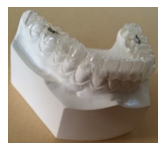
Figure 1: 3D view image of a tooth aligner fitted on a lower jaw
The PVDF actuator is primarily demonstrated as a flexible U-shaped rod fitted to the top of an aligner. It is excited and polarized along the actuator thickness restricting vibrations in the z-direction. During use, the patient bites down on the actuators, causing the actuators to only stretch axially to the surface of the aligner. The cyclic forces mentioned previously are applied longitudinally to produce directional vibrations to the structure. Figure 2a shows a plain model of the proposed device fitted to the aligner and the axial force direction.
Piezoelectric constitutive formulas are used for modeling the piezoelectric devices and are based on assumptions where the transducer’s total mechanical strain is the sum of the mechanical strain and that the controlled actuation strain results from the applied electrical voltage.
Instead of using letters to label axis, numbers will be used in its place. 1 is the x-axis, 2 will be the y-axis, and 3 is the z-axis. The third axis is parallel to the direction of polarization of the piezo ceramic device, and axis 1 and 2 are normal to axis 3.
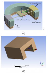
Figure 2: (a) Proposed PVDF device attached to the tooth aligner. (b) U-shape PVDF actuator/vibrator
By employing the Piezoelectric constitutive equations, the coupled electromechanical model of the piezoelectric material can be presented as:

The corresponding model is mainly presenting the stress components ( ), mechanical strain ( ), electric field ( ) and the electric displacement components ( ). is the Permittivity (F/m). (d) is the piezoelectric matrix of the strain constants (m/V). The indexes i, j = 1, 2, . . . ,6 and m, k = 1, 2, 3 are labeled for the multi-directions coordinate system, as illustrated by:
| Index | Coordinate |
| 1 | x |
| 2 | y |
| 3 | z |
| 4 | Shear about x |
| 5 | Shear about y |
| 6 | Shear about z |
Equations (1) can be given in the matrix form as:
![]()
Superscripts and define the corresponding variables that are calculated at constant electric field and stress, respectively. The superscript t is a mathematical indication for a vector transpose. The fully expanded formula of Equation (2) is outlined as:
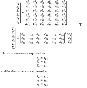
The shear stresses are expressed as:
and the shear strains are expressed as:
The electric displacement is expressed as:
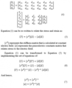
(Young’s modulus of elasticity) and (Poisson’s ratio) are indicated in Table 1. At this point and at constant electric field, the final shape of the PVDF compliance matrix can be obtained as:
represents the modulus of rigidity ( ).
The stress constants matrix of the PVDF actuator, can be represented as:
PVDF dielectric Matrix :
Employing Equation (7) and the piezoelectric constant matrix, the PVDF stiffness matrix is generated as indicated in Equations (8) and (9).
Table 1 indicates the PVDF material physical properties.
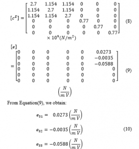
Table 1: PVDF material properties
| Density (kg/m3) | 1,780 | 0.3 | (GPa) | 2.0 |
2.2. PVDF actuator electromechanical model at e31 mode
Figure 3 visualizes a PVDF actuator where the electric field is in the direction of the PVDF thickness. The positive sign of the electric field indicates a same direction as for the polarization, and this is analytically analyzed by implementing the distributed parameter approach. Finite Element Method (FEM) software such as ANSYS is utilized to verify the introduced analytical model.
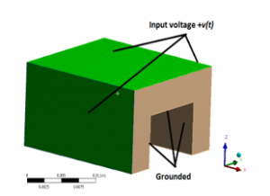
Figure 3: U-shape PVDF actuator/vibrator at actuation mode showing an electric field E in the direction of the material thickness
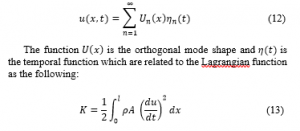
It must be noted that the electromechanical model is derived based on the assumption that the PVDF actuator is solely poled along the z-axis (the PVDF thickness direction) where the stress and strain are undertaken axially along the direction of actuator length (x-direction). At this point, the energy method can be employed to generate the dynamic model of the PVDF actuator. Consequently, the coupled electromechanical model is generated by utilizing the so called Hamilton’s principle that takes the variation of a function with respect to time. According to Hamilton’s principle the Lagrangian (L) function is defined as:
![]()
K is the kinetic energy. is the stored electrostatic energy. The PVDF actuator will be represented as a rod. The physical properties of the proposed elastic PVDF bar are labeled as: length l, width b, mechanical stiffness at constant electric field , mass density ρ and the cross-sectional area A.
At this point, the absolute displacement of the PVDF actuator as a function of x and time is indicated by . Using the principle of separation of variables, the solution is written as:
is the piezoelectric constant at a constant stress and the electric field as a function of voltage is ( ) [57]. Based on Hamilton’s principle, the variation of the function with respect to respect to time equals to zero:
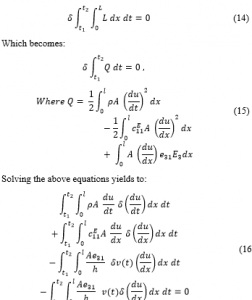
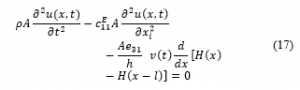
represents the Heaviside function.
At this stage, we evaluate the cyclic forces produced by the proposed PVDF actuators excited over a certain range of constant voltages by implementing of statically indeterminate structures principle.
The equilibrium equations relate structural deformations in such way to obtain the reaction forces. Consequently, due to the linearity of the system, the superposition method is implemented to obtain the corresponding forces by assuming that one of the reaction forces is redundant. This force is considered as an unknown load, which together with the other loads must produce deformations that match the original constrains (see Figure 4 for details). indicates the elongation of the rod.
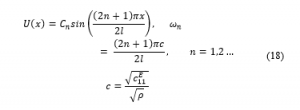
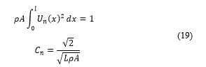
The mode shapes at this point can be generated for a fixed-fixed rod to estimate the axial forces produced by the PVDF actuator.
The mode shapes presented as a function of the natural frequency are written as:
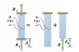
Figure 4: Free body diagram of a statically indeterminate rod
The dimensions of the PVDF actuator used in the study are shown in Table 2:
Table 2: Piezoelectric PVDF actuator physical dimensions
| PVDF Dimensions | Quantity |
| Length (L) | 20 mm |
| Cross section’s outer edges length (b) | 31 mm |
| Thickness (h) | 4 mm |
Figure 5 illustrates the estimated axial forces generated by the PVDF actuator. that shows the data of the actuator when it is stimulated by a wide range of Direct Current (DC) voltage.
The results obtained analytically are numerically validated at actuation mode of with the help of a finite element FEM solver, namely ANSYS. In addition, Figure 5 indicates that the optimum external force produced by the PVDF actuator which is approximately equal to 8.5 grams at an excitation voltage of 100 volts. This resulted force can be transmitted to a group of four teeth.
As can be clearly observed from Figure 5, the axial force is proportional with the voltage due to the linearity of the system.
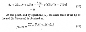
Applying a harmonic voltage (which is represented by ), with the requirements of achieving a high amplitude cyclic forces, the PVDF actuators should normally have a fundamental natural frequency matching the harmonic voltage excitation frequency.
The damping has a major effect on the response of the system. Therefore, we can include the viscoelastic linear effect and hence the modulus of elasticity (the stiffness constant) under a constant electric field can be defined as:
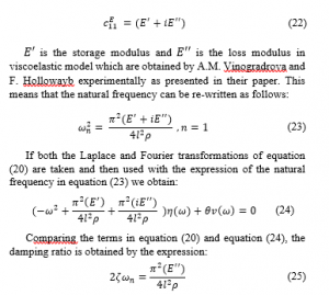
Comparing the terms in equation (20) and equation (24), the damping ratio is obtained by the expression:
A frequency response function (FRF) of the force over a wide range of excitation frequencies is shown below, and Figure 6 contains the plot of this function:
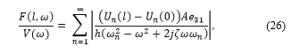
Figure 6 indicates the maximum axial force which is normally obtained at the resonance. However, because of the compact size of the PVDF actuator, the PVDF actuator natural frequencies are presented in kilohertz. Consequently, matching the exciting frequency with one of the PVDF actuator fundamental natural frequencies is not attainable. That being said, based on a study performed by Rubin revealed that a low frequency vibration (30 Hz to be exact) generated forces with a preferred magnitude to rapidly accelerate the tooth bone remodeling in comparison to a high magnitude and frequency force. Therefore, the cyclic forces are generated at 30 Hz harmonic voltage.
As can be seen in Figure 7, the cyclic forces in grams per unit voltage evaluated analytically are compared to their equivalents obtained by the FEM analysis. Comparison is performed only at the actuation mode. As shown in Figure 7, both methods are in perfect agreement.
When examining Figure 6 and Figure 7, it can be seen that the absolute value of the harmonic forces are equivalent to the ones obtained in Figure 5. The reasoning behind this is that the harmonic voltage frequency is way smaller than the corresponding 1st fundamental natural frequency of the PVDF piezoelectric actuator. As a result, the system can be assumed to be a quasi-static (i.e. the system changes so slowly and hence can be treated to be always at equilibrium).
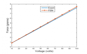
Figure 5: Exact and FEM axial force Vs voltage at actuation mode
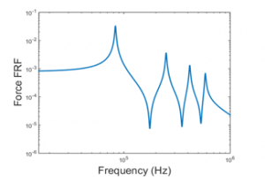
Figure 6: Force frequency response function actuation mode
In order to improve the total generated axial force, the actuator design parameters denoted by the length, thickness and width of the actuator are analyzed.
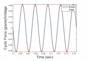
Figure 7: Analytically and numerically obtained cyclic forces in grams per unit voltage at 30 Hz at actuation mode
By using equation (21) with sinusoidal harmonic input voltage denoted as , where V being the amplitude and ω being the excitation frequency (= 30 Hz), the following expression for the force (in Newtons) is obtained:
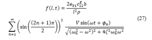
In a polarized system in the z-axis in the actuation mode, it can be seen from Equation (27) that the actuator thickness has no effect on resulting force. In addition, in reference to the natural frequency in Equation (18), a conclusion can be made from Equation (27) that the PVDF actuator length has a minimal effect on the resulting axial force, as observed in Figure 8. For this particular case, the actuator thickness of 4 mm is chosen to be consistent with the aligner thickness and hence keeps the device lightweight and compact.
From Equation (27) and Figure 9, an observation can be made that the actuator width is linearly proportional to the resulted axial force.
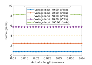
Figure 8: The variation of axial force with PVDF actuator length at different voltage inputs at actuation mode
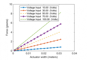
Figure 9: The variation of axial force with PVDF actuator width at different voltage inputs at actuation mode
2.3. Electromechanical model of PVDF actuator at full actuation mode, Equation (3)
In this analysis, and actuation modes are all utilized. Basically, the effect of the implies that a strain and a stress are produced in the lateral direction namely, the y-axis. This behavior is usually observed in plates. This behavior can be analytically modelled when the actuator is excited in and actuation mode. In this case, the normal stresses are parallel to the x and y axis ( , ), with the shear stress acting in the xy-plane ( .
The plate’s bending deformation has no pairing with the shear deformation, and by assuming that the normal stress to the middle plane of the un-deformed plate remains straight and perpendicular to the mid plane after deformation, the stresses that are within the plane of any point through the thickness of the PVDF plate in a state plane stress can be written as:
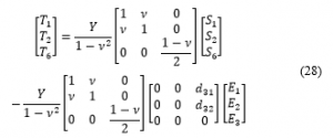
The expressions for the strains in Equation (28) can be found in the literature. However, we use the Finite Element Technique to implement the full actuation matrix in Equation (3) using ANSYS. This is because implementing the full piezoelectric stress constants matrix [e] and analytically deriving the analytical electromechanical model of the U-shape PVDF actuator complicates the model significantly. ANSYS provides a convenient way to obtain the results using the FEM.
In ANSYS, we are able to study the effect of the different piezoelectric constants at constant stress as discussed previously.
Figure 10 compares the maximum axial force generated by the PVDF actuator at two actuation modes; full matrix actuation and modes. The maximum axial force that is obtained at full matrix actuation mode is perfectly matches the force obtained in the analytical and FEM models in actuation mode discussed previously. Therefore, the analytical model in actuation mode is sufficient to depict the system.
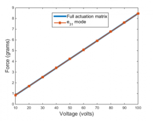
Figure 10: Axial force comparison by FEM at full matrix actuation and actuation mode
It must be noted that, the axial force is applied to four teeth; two in the bottom and two on the top of the actuator as we will see that later in this section. Since it is a linear system, the force and the applied voltage have a linear relationship, as shown in Figure 10.
The material friction coefficient is defined as the measure of the sliding resistance of one material over another. In this case, the PVDF actuator’s contact part is a standard aligner which is usually made of industrial plastic, as shown in Figure 2.
To calculate the required force that is required to prevent sliding the actuators and aligner across each other, we need to calculate the required perpendicular/normal biting force between the mating sliding faces as the following:
![]()
where, is the normal force, is the co-efficient of friction and equals to 0.18 and is the axial force by the PVDF actuators. Therefore, the required biting force should be at least equal or larger than 48 grams’ force.
2.4. Actual model of the PVDF actuator at full actuation mode, Equation (3)
In this section we discuss the actual U-shaped model of the PVDF actuator as illustrated in Figure 11.
Figure 11 is clearly annotated to indicate the targeted teeth, the direction of the axial force and the side wings of the U-shaped PVDF actuator.
A single actuator exerts forces on the upper and lower teeth that are in contact with the it. The forces generated by the actuator are equally spread among the teeth above and below the actuator.
The axial force is calculated by implementing the FEM principle with the help of commercial FEM software, namely ANSYS. The results are then compared to the analytical model introduced previously in this paper for the U-shaped PVDF actuator.
Figure 12 shows the total force generated by the actuator to the front/back and upper/lower teeth in comparison to that obtained analytically. The deviation of the forces are due to the side wings of the actuator.
The single layer PVDF actuator with now side wings, is shown in Figure 13.
In Figure 14, the total force generated by the single layer actuator on the front/back upper and lower teeth is compared that obtained analytically for single layer actuator with no wings.
Figure 14 clearly reveals that the results are in good agreement. As a result, the conclusion can be made that the side wings of the actual model don’t have any effect on the total resulted axial force.
We can simulate the stress build-up at the fixed ends and the total deformation at the free ends of both; the actual U-shaped and single layer PVDF actuators as we can see in Figure 15.
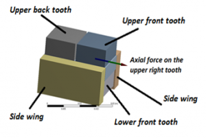
Figure 11: The actual U-shaped PVDF actuator
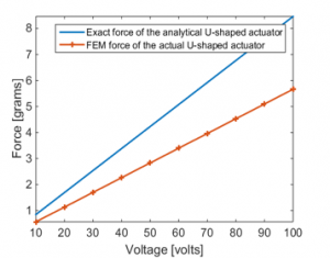
Figure 12: Total axial force comparison between actual and analytical U-shaped PVDF actuator
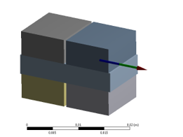
Figure 13: The actual single layer PVDF actuator
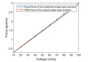
Figure 14: Total axial force comparison between actual and analytical single layer PVDF actuator
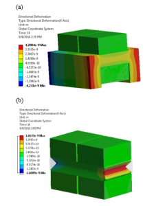
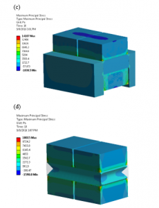
Figure 15: Total deformation in meters at the free ends of (a) U-shaped PVDF and (b) Single layer PVDF actuators. Normal stresses building up at fixed-fixed ends in Pascals (c) U-shaped PVDF and (d) Single layer PVDF actuators.
2.5. AcceleDent® versus the proposed PVDF vibrator
In 2006, Mao introduced a dental appliance which utilized pulsating forces to improve tooth movement rate, namely AcceleDent by OrthoAccel. The device is optimized in terms of force magnitude and frequency which enhances the comfort level and patient compliance to the treatment. The appliance is used twice a day for a duration of 10 minutes during the orthodontic treatment process and can be utilized along with a fixed appliance or an aligner treatment device. This device also provided an average of 23 to 25 grams of output force at 30 Hz frequency. Figure 16.a shows a one-time cycle of force output at 23 grams and at a low frequency of 30 Hz, while Figure 16.b displays an illustration of the AcceleDent device.
In Figure 16.b, the arrow shows the produced force by the extra-oral component of the vibrator. OrthoAccel made the claim that the resulting axial force of their device is equally dispersed among the upper and lower teeth, but that is not the case. In order to defend our claim, ANSYS was utilized to find the applied forces to the jaws produced by the AcceleDent device. The forces are then compared to the ones produced by the proposed PVDF piezoelectric actuator to each corresponding tooth based on the outcome and findings obtained in previous sections of this paper. Table 3 shows the material properties of the jaw bone, AcceleDent and the tooth.
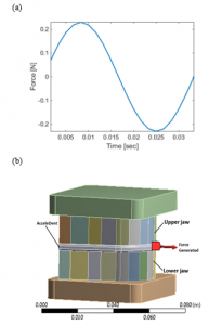
Figure 16: (a) One cycle of force by AcceleDent at 23 grams and 30 Hz (b) Simplified illustration of the AcceleDent with the lower and upper jaws assembly.
Table 3: Material properties of piezoelectric PVDF material
| Component | Material | Density(kg/m3) | (GPa) |
| AcceleDent | Versaflex™ CL2250 ~clear/ transparent thermoplastic elastomer (TPE) grade1 | 888 | 0.0139 |
| Jaw Bone | Cortical (surrounding), Cancellous (core) | 1180 | 18.3 |
| Teeth | Dentine | 1200 | 84.1 |
1Source: The University of Texas Health Science Center at San Antonio
It can be seen from Figure 17.a that the force created by the AccelDent device is not evenly dispersed among all of the teeth. Most part of the generated force by the AccelDent device was concentrated at the top front teeth of the jaws. While, as indicated Figure 17.b, the proposed PVDF device at a specific voltage magnitude and frequency, provides precise cyclic forces to a precise location of the tooth aligner, which then channels the forces to the targeted teeth. As a result, this allows flexibility of the tooth treatment for patients for the treatment process as the device can be adjusted.
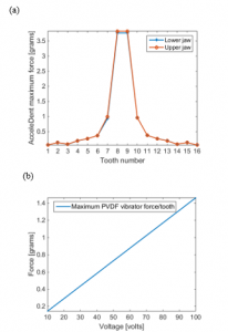
Figure 17: (a) Force distribution among all the teeth by AcceleDent (b) Force generated by the proposed single layer PVDF actuator at each targeted tooth versus voltage input.
3. Conclusion
In this paper, a novel dental vibratory apparatus was proposed in order to enhance the patient compliance to a vibration based orthodontic treatment as well as to minimize the time required for the treatment while simultaneously maintaining an acceptable level of comfort. The vibrating component of the device consisted of a bio-compatible smart material, namely (PVDF) piezoelectric actuators excited via voltage function generator at a frequency of 30 Hz over wide range amplitudes. The proposed device could be fitted to a tooth aligner and consequently provided recurring/cyclic forces to a particular part of the aligner, which then transmits these produced forces to the corresponding teeth.
The proposed model of the PVDF actuator was obtained both analytically and numerically with the help of ANSYS. The ultimate force obtained was 7.3 grams at the front and back teeth. This proposed device in particular is compact in size in comparison to its competition. The vibrating component of the device can be relocated and repositioned along the tooth aligner for customized fits, and it also compromises: the vibrating component and the intra-oral voltage function generator, battery, and processer are in a single device. This device is also predicted to minimize the drooling associated with the current orthodontic treatments. It ultimately enhances the overall experience for the orthodontic treatment process and increases the chances of patient compliance.
Acknowledgment
Sincere thanks and appreciation to students Steven Lin, Raymond Huang and their effort of proofreading the paper. Special thanks to Olivia Licata for her effort in correcting related grammatical errors and providing the 3D image of a tooth aligner,
- M. B.-H. a. M. A. Karami, “Piezoelectric Tooth Aligner for Accelerated Orthodontic Tooth Movement,” in 2018 40th Annual International Conference of the IEEE Engineering in Medicine and Biology Society (EMBC), Honolulu, HI, 2018.
- A. M. Schwarz, “Tissue changes incidental to orthodontic tooth movement,” International Journal of Orthodontia, Oral Surgery and Radiography, vol. 18, pp. 331-352, 1932.
- D. F. Fink and R. J. Smith, “The duration of orthodontic treatment,” American Journal of Orthodontics and Dentofacial Orthopedics, vol. 102, pp. 45-51, 1992.
- M. A. Fisher, R. M. Wenger, and M. G. Hans, “Pretreatment characteristics associated with orthodontic treatment duration,” American Journal of Orthodontics and Dentofacial Orthopedics, vol. 137, pp. 178-186, 2010.
- A. M. Geiger, L. Gorelick, A. J. Gwinnett, and B. J. Benson, “Reducing white spot lesions in orthodontic populations with fluoride rinsing,” American Journal of Orthodontics and Dentofacial Orthopedics, vol. 101, pp. 403-407, 1992.
- S. E. Bishara and A. W. Ostby, “White spot lesions: formation, prevention, and treatment,” in Seminars in Orthodontics, 2008, pp. 174-182.
- G. Segal, P. Schiffman, and O. Tuncay, “Meta analysis of the treatment related factors of external apical root resorption,” Orthodontics & craniofacial research, vol. 7, pp. 71-78, 2004.
- N. Pandis, M. Nasika, A. Polychronopoulou, and T. Eliades, “External apical root resorption in patients treated with conventional and self-ligating brackets,” American journal of orthodontics and dentofacial orthopedics, vol. 134, pp. 646-651, 2008.
- A. Royko, Z. Denes, and G. Razouk, “[The relationship between the length of orthodontic treatment and patient compliance],” Fogorvosi szemle, vol. 92, pp. 79-86, 1999.
- G. T. Sameshima and P. M. Sinclair, “Predicting and preventing root resorption: Part I. Diagnostic factors,” American Journal of Orthodontics and Dentofacial Orthopedics, vol. 119, pp. 505-510, 2001.
- L. Linge and B. O. Linge, “Patient characteristics and treatment variables associated with apical root resorption during orthodontic treatment,” American Journal of Orthodontics and Dentofacial Orthopedics, vol. 99, pp. 35-43, 1991.
- M. Harry and M. Sims, “Root resorption in bicuspid intrusion: a scanning electron microscope study,” The Angle orthodontist, vol. 52, pp. 235-258, 1982.
- A. H. Ketcham, “A preliminary report of an investigation of apical root resorption of permanent teeth,” International Journal of Orthodontia, Oral Surgery and Radiography, vol. 13, pp. 97-127, 1927.
- D. R. Cruz, E. K. Kohara, M. S. Ribeiro, and N. U. Wetter, “Effects of low-intensity laser therapy on the orthodontic movement velocity of human teeth: A preliminary study,” Lasers in surgery and medicine, vol. 35, pp. 117-120, 2004.
- M. Yamaguchi, M. Hayashi, S. Fujita, T. Yoshida, T. Utsunomiya, H. Yamamoto, et al., “Low-energy laser irradiation facilitates the velocity of tooth movement and the expressions of matrix metalloproteinase-9, cathepsin K, and alpha (v) beta (3) integrin in rats,” The European Journal of Orthodontics, vol. 32, pp. 131-139, 2010.
- R. Showkatbakhsh, A. Jamilian, and M. Showkatbakhsh, “The effect of pulsed electromagnetic fields on the acceleration of tooth movement,” World J Orthod, vol. 11, pp. e52-e56, 2010.
- D.-H. Kim, Y.-G. Park, and S.-G. Kang, “The effects of electrical current from a micro-electrical device on tooth movement,” Korean Journal of Orthodontics, vol. 38, pp. 337-346, 2008.
- A. H. Hassan, A. A. Al-Fraidi, and S. H. Al-Saeed, “Corticotomy-assisted orthodontic treatment: review,” The open dentistry journal, vol. 4, 2010.
- S. M. B. E.-D. Aboul, A. R. El-Beialy, K. M. F. El-Sayed, E. M. N. Selim, N. H. EL-Mangoury, and Y. A. Mostafa, “Miniscrew implant-supported maxillary canine retraction with and without corticotomy-facilitated orthodontics,” American Journal of Orthodontics and Dentofacial Orthopedics, vol. 139, pp. 252-259, 2011.
- E. J. Liou and C. S. Huang, “Rapid canine retraction through distraction of the periodontal ligament,” American journal of orthodontics and dentofacial orthopedics, vol. 114, pp. 372-382, 1998.
- S. Sayin, A. O. Bengi, A. U. Gürton, and K. Ortakoğlu, “Rapid canine distalization using distraction of the periodontal ligament: a preliminary clinical validation of the original technique,” The Angle Orthodontist, vol. 74, pp. 304-315, 2004.
- H. İşeri, R. Kişnişci, N. Bzizi, and H. Tüz, “Rapid canine retraction and orthodontic treatment with dentoalveolar distraction osteogenesis,” American journal of orthodontics and dentofacial orthopedics, vol. 127, pp. 533-541, 2005.
- M. Nishimura, M. Chiba, T. Ohashi, M. Sato, Y. Shimizu, K. Igarashi, et al., “Periodontal tissue activation by vibration: intermittent stimulation by resonance vibration accelerates experimental tooth movement in rats,” American Journal of Orthodontics and Dentofacial Orthopedics, vol. 133, pp. 572-583, 2008.
- I. Bautmans, E. Van Hees, J.-C. Lemper, and T. Mets, “The feasibility of whole body vibration in institutionalised elderly persons and its influence on muscle performance, balance and mobility: a randomised controlled trial [ISRCTN62535013],” BMC geriatrics, vol. 5, p. 1, 2005.
- V. Gilsanz, T. A. Wren, M. Sanchez, F. Dorey, S. Judex, and C. Rubin, “Low-level, high-frequency mechanical signals enhance musculoskeletal development of young women with low BMD,” Journal of Bone and Mineral Research, vol. 21, pp. 1464-1474, 2006.
- N. Gusi, A. Raimundo, and A. Leal, “Low-frequency vibratory exercise reduces the risk of bone fracture more than walking: a randomized controlled trial,” BMC musculoskeletal disorders, vol. 7, p. 1, 2006.
- H. Omar, G. Shen, A. S. Jones, H. Zoellner, P. Petocz, and M. A. Darendeliler, “Effect of low magnitude and high-frequency mechanical stimuli on defects healing in cranial bones,” Journal of Oral and Maxillofacial Surgery, vol. 66, pp. 1104-1111, 2008.
- A. E. Goodship, T. J. Lawes, and C. T. Rubin, “Low-magnitude high-frequency mechanical signals accelerate and augment endochondral bone repair: Preliminary evidence of efficacy,” Journal of orthopaedic research, vol. 27, pp. 922-930, 2009.
- C. Rubin, A. S. Turner, S. Bain, C. Mallinckrodt, and K. McLeod, “Anabolism: Low mechanical signals strengthen long bones,” Nature, vol. 412, pp. 603-604, 2001.
- J. Rubin, C. Rubin, and C. R. Jacobs, “Molecular pathways mediating mechanical signaling in bone,” Gene, vol. 367, pp. 1-16, 2006.
- C. Rubin, S. Judex, and Y.-X. Qin, “Low-level mechanical signals and their potential as a non-pharmacological intervention for osteoporosis,” Age and Ageing, vol. 35, pp. ii32-ii36, 2006.
- Z. Kalajzic, E. B. Peluso, A. Utreja, N. Dyment, J. Nihara, M. Xu, et al., “Effect of cyclical forces on the periodontal ligament and alveolar bone remodeling during orthodontic tooth movement,” The Angle Orthodontist, vol. 84, pp. 297-303, 2013.
- S. Yadav, T. Dobie, A. Assefnia, H. Gupta, Z. Kalajzic, and R. Nanda, “Effect of low-frequency mechanical vibration on orthodontic tooth movement,” American Journal of Orthodontics and Dentofacial Orthopedics, vol. 148, pp. 440-449, 2015.
- M. C. Meikle, J. J. Reynolds, A. Sellers, and J. T. Dingle, “Rabbit cranial sutures in vitro: a new experimental model for studying the response of fibrous joints to mechanical stress,” Calcified Tissue International, vol. 28, pp. 137-144, 1979.
- C. H. Kurz, “Pulsating orthodontic appliance,” ed: Google Patents, 1981.
- C. H. Kurz, “Pulsating orthodontic appliance,” ed: Google Patents, 1982.
- C. H. Kurz, “Radio wave vibrational orthodontic appliance,” ed: Google Patents, 1983.
- W. G. Branford, “Vibratory dental mouthpiece,” ed: Google Patents, 1991.
- M. J. Powers, “Hand held device for reducing the discomfort associated with the adjusting of orthodontic appliances,” ed: Google Patents, 1999.
- J. C. Voudouris, “Powered orthodontic bracket,” ed: Google Patents, 2003.
- M. K. Lowe, “Vibrating dental devices,” ed: Google Patents, 2015.
- C. T. Rubin, W. B. Tarver, and M. K. Lowe, “Vibrating compressible dental plate for correcting malocclusion,” ed: Google Patents, 2009.
- J. J. Mao, “Use of cyclic forces to expedite remodeling of craniofacial bones,” ed: Google Patents, 2006.
- N. Mandall, C. Lowe, H. Worthington, J. Sandler, S. Derwent, M. Abdi-Oskouei, et al., “Which orthodontic archwire sequence. A randomized clinical trial,” The European Journal of Orthodontics, vol. 28, pp. 561-566, 2006.
- K. O’Brien, D. Lewis, W. Shaw, and E. Combe, “A clinical trial of aligning archwires,” The European Journal of Orthodontics, vol. 12, pp. 380-384, 1990.
- “Tooth positioner,” ed: Google Patents, 1968.
- C. H. Kurz, “Vibrational orthodontic appliance,” ed: Google Patents, 1982.
- M. K. Lowe, C. L. Wasden, and W. B. Tarver, “Systems, methods, and adjunctive procedures for correcting malocclusion,” ed: Google Patents, 2007.
- H. M. Layson Jr, “Body worn active and passive tracking device,” ed: Google Patents, 2000.
- M. G. Strugach and A. Szilagyi, “Piezoelectric vibrating device,” ed: Google Patents, 1998.
- S. H. An, “Flat Vibration Motor,” ed: Google Patents, 2006.
- M. K. Lowe, “Vibrating orthodontic remodelling device,” ed: Google Patents, 2013.
- X. Chen, S. Xu, N. Yao, and Y. Shi, “1.6 V nanogenerator for mechanical energy harvesting using PZT nanofibers,” Nano letters, vol. 10, pp. 2133-2137, 2010.
- A. Holmes-Siedle, P. Wilson, and A. Verrall, “PVdF: An electronically-active polymer for industry,” Materials & Design, vol. 4, pp. 910-918, 1983.
- T. Sato, H. Ishikawa, and O. Ikeda, “Multilayered deformable mirror using PVDF films,” Applied optics, vol. 21, pp. 3664-3668, 1982.
- J. Ha, H. O. Lim, and N. J. Jo, “Actuation behavior of CP actuator based on polypyrrole and PVDF,” in Advanced Materials Research, 2007, pp. 363-366.
- A. Meitzler, H. Tiersten, A. Warner, D. Berlincourt, G. Couqin, and F. Welsh III, “IEEE standard on piezoelectricity,” ed: Society, 1988.