Non Parallelism and Cayley-Menger Determinant in Submerged Localization

Adv. Sci. Technol. Eng. Syst. J. 5(3), 150–157 (2020);
 DOI: 10.25046/aj050320
This research paper portraits the technique to determine location of submerged nodes with Cayley-Menger determinant and associated problems with non-parallel states. Cayley-Menger determinant is considered to be the usual means to determine the coordinates of the nodes with a single node where the plane of beacon i.e. beacon’s surfing plane and the plane created by the deployed submerged sensors are in parallel state. However, this perfect scenario hardly exists in the submerged world; as a result Cayley-Menger determinant may not be used unless proper measurements are taken. This paper addresses this limitation and analyzed the proposed model to deal with this non-parallel state situation. As precise localization is vital for the validity of the sensed data in Underwater Wireless Sensor Networks (UWSNs); exact distance measurement between nodes is an important and crucial in range based localization methods. Proposed method has addressed uncertainty of nonlinear equations as well as how better immunity could be achieved in multipath fading in propagation. Analyzed simulation and experimental results conclude the accuracy of the proposed model with minimal error, where it has been shown that parallelism of the system is not a factor for using Cayley-Menger determinant. Moreover, a single node has been used in the model to localize submerged nodes where none acquires priori familiarity about its position.
1. Introduction
Underwater wireless sensor networks (UWSNs) are envisioned for exploring the vast underwater world for the profusion of wealth and mystery. Not only the wealth of underwater world, submerged localization necessary for the sustenance of our very own existence and for the marine biome. Lately researchers have shown fervent importance to investigate, explore and analyze the abundance of underwater world; so it has become indispensable to collect accurate environmental data with the help of underwater sensors. Exact localization is not only necessary for underwater applications; it determines the very nature of our own existence at rudimentary and core level as well as helps us to provide a sanctuary for the marine biome. Moreover, autonomous underwater vehicles (AUVs) control and surveillance, monitoring seabed and faults for upcoming natural calamity, searching for lost object, pollutants and nutrients tracking also demand precise localization [1]. Among these applications, some significantly requires accurate localization for meaningful comprehension of gathered data for a practical use [2].
UWSNs may comprise of deployed sensors and surface stations; many a time localization of submerged sensors is done with the help of multiple surfaced nodes. However, localizing using a single beacon is considered to be pragmatic as it requires less provision. Despite numerous underwater applications, the concept and achievement of underwater wireless communication may still seem far-fetched. Mostly, communications is done with acoustic signals as radio signals have very limited propagation in underwater; hence, using acoustic signals for distance measurements in range based localization provides more accuracy that using radio [1,3]. However, multipath fading and synchronization between communicating nodes still remain to be the challenging factors so far.
Duff and Muller solved system of multilateration equations by applying nonlinear square optimization method where positions of the sensors remain unknown [3]. This proposed algorithm is solely based on degree-of-freedom analysis phenomenon, which dictates sufficient numbers of measurements are necessary to generate adequate number of equations for the problem to solve. This proposed method has been validated and showed the improved accuracy by many folds using Kalman filter in [4]. Incorporation of Kalman filter increases the complexity of the method with respect to degree-of-freedom complexity of system of equations in [5]. It also delineates that the method does not guarantee a unique solution for system of non-linear equations, i.e. trilateration. Moreover, the method requires a specific initial configuration of the nodes which was justified by rigidity theory. 3D positioning system in [6] requires four separate positions to determine the coordinates of the beacon.
This paper analyzed the method proposed in [7] to determine the coordinates of underwater sensors with a single beacon where Cayley-Menger determinant is used for non- parallel situation and validates the method with simulation and experimentation. Recently, localization of submerged sensors for non-parallel states has been proposed in [8]. It also showed that the coordinates could be determined in adhoc basis without any pre-installed infrastructure. Moreover, it has established that the accuracy of the coordinates depends on the distance measurements between surfaced node and underwater deployed sensors, not the state of the planes whether parallel or non-parallel.
The arrangement of the remaining paper is as following where Section 2 focuses on mathematical model of coordinates determination both for parallel and non-parallel state situations; it also talks about linear transformation of the origin to find the coordinates with respect to sensor and beacon separately. Section 3 states simulation to validate the proposed mathematical model, experimental results also shows the accuracy of the model and at last analysis. Section 4 states conclusion with future works.
2. Coordinates Determination
The proposed algorithm in [9] was to determine the coordinates of the submerged sensors with a single beacon; the problem domain was considered to be in parallel state which is only possible in perfect world. However, in [7] Cayley-Menger determinant has been used for non-parallel state situation. Following sections iterates the proposed algorithm for parallel and non-parallel states.
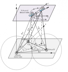
Figure 1: Coordinates Determination Coordinates determination
2.1. Coordinates Determination (parallel state)
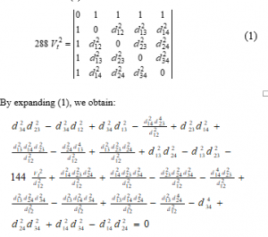
The problem domain consists of a single beacon which is on the water surface and three underwater sensors whose coordinates need to be determined. For simplicity, one of the sensors is considered to the Cartesian origin and one other placed on another axis leaving the third one on the same quadrant. The distance between the beacon and the deployed sensors have been computed according to the process depicted in [10], these measured values are and unknown inter nodes distances are From these values, volume of the tetrahedron which is created by the beacon and the deployed sensors depicted in Figure 1can be written with Cayley-Menger determinant as in (1).
By isolating and grouping known and unknown variables:
The above equation has six unknowns as depicted by X1, X2, X3, X4, X5 and X6; and the equation resembles with the linear form of These six unknowns are solved by taking six measurements by steering the beacon in six different positions. It is worth mentioning that while taking measurements the deployed submerged nodes are stationary; mobility of the submerged nodes is out of the scope of this paper. To get better results, distance measurements are taken within close proximity of the beacon so that in real life the movement would be less between distance measurements. From these six equations reference to the variables have been omitted to get an array of all coefficients, which is represented as augmented matrix. The matrix consists of linear equations and resembles formula. So, the system of linear equations is articulated as following:
From the above representation, after finding and we calculate , and as follows:
Coordinates of deployed submerged sensors is considered to be the origin of the Cartesian system, is on one of the y-axis and is considered on some position not on the axis as depicted in Figure 1. From the above equations, the inter node distances can be calculated as follows:
As a result, the unknown variables and can be derived with respect to inter node distances:
Here, , and are computed distances between deployed submerged sensors and Table 1 shows the coordinates of the sensors as follows:
2.2. Coordinates with respect to Beacon (parallel state)
So far the previous section has dealt with determination of coordination when beacon’s surfing plane and plane of deployed submerged sensors are in parallel. Once the transformation of the origin takes place and taken to the beacon’s position, the localization process would be following.
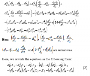
In this method, a pressure sensor is used to measure the depth h of Figure 2, which is elaborated in [11]. Once vertical distance (h) between the planes is known, the projected coordinates of the beacon can be found on the plane and can be denoted as Trilateration can be used to find and of the projected coordinates considering , and to be the distances between and respectively. Once the projected coordinates and the distances are determined, following relations can be devised.
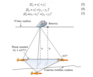
Figure 2: Parallel Plane State Scenario
Equations (3), (4) and (5) help to determine the coordinates of the projected beacon , where
Here, , and are the hypotenuse of the , and respectively, so it is possible to obtain and using simple Pythagorean Theorem. As a result, the coordinate of the beacon node that is on the surface, would be here both and have been calculated accordingly and is known from the installed pressure sensor. So, the coordinates of would be as follows:
Once the origin of the Cartesian system is transferred on the beacon then the coordinates of the deployed sensors with respect to beacon are calculated by linear transformation as depicted in [10].
2.3. Coordinates with respect to Beacon (non-parallel state)
Having the plane where the beacon moves around i.e. water surface and the plane that is created by the three deployed sensors in parallel state can be found in very limited situations. Previous coordinates determination method could be adjusted to meet all the situations both parallel and non-parallel. As a result, a derivative of parallel state method has been illustrated in [8]; however this paper also shows the relationship between Cayley-Menger and state of the planes. With a little adjustment as depicted in this section where Figure 3 illustrates the scenario when both planes are in non-parallel state situation.
Here, plane A is created by the submerged deployed sensors , , and as three dots (sensors) can create a plane. Whereas,
Here, plane B is where the beacon moves around while taking six distance measurements i.e. water surface, are in non-parallel state.
Figure 3 is the most likely the situation found in the world, except in some special cases like, water tank, swimming pools or where the deployed sensors can maintain a predefined height like AUVs or UUVs as in Figure 2. When we consider the water surface as the reference plane then any deployed node having a different height than others would create a non-parallel state situation. The system of equations and the linearization procedure devised in previous section are meant to be used in parallel state; as volume of six different tetrahedrons created by deployed submerged sensors and the surfaced beacon are always equal. Once apex of six tetrahedrons on the same parallel plane having the base same i.e. the height of the tetrahedrons are same having the base fixed, the volume would be same. This fundamental theory creates the scope to use the devised equations in previous section. Vertical distances will vary depending on the dihedral angle α accordingly to the (6).
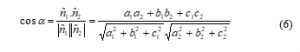
Here, α dihedral angle; and are normal vectors to plane A and plane B respectively.
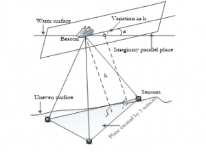
Figure 3: Parallel Planes Effect
It is worth mentioning that all the deployed submerged nodes have several sensors for communication purposes; among them pressure is one of them. Nodes are supposed to read water pressure and communicate to beacon node via acoustic signals where the pressure reading will be converted into depth following method devised in [12]. Once all three sensors’ depth is known, following method would be applied to determine the coordinates. Figure 4 illustrates a solvable configuration.
At this point of the procedure all three deployed submerged sensors’ depth would be known from the built-in pressure sensors. Let these depth be , and for the sensors , and respectively. These depths could be all equal, which would be consider as parallel plane state; however, if any one of them is different than the others, that situation would be considered as non-parallel state. Assuming is at the lowest point whereas is at the highest point among all the three sensors with depth and respectively. In this situation, it is conspicuous that plane where beacon surfs i.e. water surface and the plane created by three submerged sensors i.e. , and would be in non-parallel state.
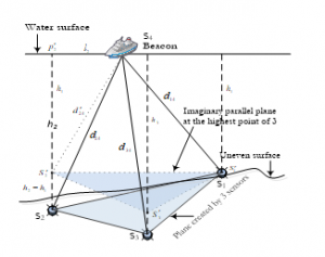
Figure 4: Parallel State in Non-parallel Situation
Let the shortest depth or highest point be , where , considering and are be two points where exactly right above and having equal depth with here the coordinates of and would be same as and except z component as these points are right above the nodes. As a result, the plane would be in parallel state with the plane .
Figure 5: Trilateration and Coordinates Computation
In , where is the projection point right above and is the measured distance what we get with acoustic signal as delineated in [13]. The distance can be calculated from Once is known, the distance may be calculated from the according to (9).
![]()
The aforesaid mentioned technique will be followed to calculate distances between the beacon and the point . Once both distances between beacon to points and are determined, coordinates determination procedure will begin for all imaginary points as well as for all the deployed submerged sensors.
Table 2 and 3 show the calculated coordinates for parallel and non-parallel states respectively. So, the devised procedure – Cayley-Menger determinant with a single beacon can be used for both parallel and non-parallel state situations with a little adjustment.
3. Simulation and Experimental Results
To validate and analyze the proposed model, a simulation has been conducted in Matlab for an aforesaid problem domain; later a stringent experiment has been performed with ultrasonic sensors in terrestrial environment to reinforce the proposed method.
3.1. Simulation Results
The problem domain imitates a scenario for a 200m water column where a single beacon has been used. The method has been devised in [9] elaborately where a group of three sensors are place arbitrarily and a single beacon is placed to imitate the surfaced sensor. The plane where the sensors have been deployed considered being XY plane and the beacon’s surfing area has been considered to be parallel to XY plane. First sensor’s coordinate is (0,0,0), which is considered to be the origin of the Cartesian system; whereas the second sensor’s is placed on (0,75,0) being on the y-axis. Lastly, the third sensor was placed on (80,40,0) where z component is zero like others. Other environmental variables for the water column are – 30oC at the surface and 15oC at the bottom where sensors are deployed having a salinity variation of 0.5ppt between surface and XY plane. Gaussian noise with (μ=0, σ=1) has been added to bottom temperature as well as with flight time of acoustic signals from beacon to submerged nodes.
As the procedure demands, the surfaced sensors has been shifted and measured from six different places; all these six positions were in close proximity to mitigate error incorporation. However, mobility of the deployed sensors were ignored in the proposed model as this is out of the scope of this paper. Possible errors in determined coordinate of and are shown in Figure 6 and 7 for several iterations. As sensor has been kept at the origin of Cartesian coordinate system; hence generating no error. Having positional distance error of 0.62m with standard deviation of 0.478 for sensor and 0.75m with standard deviation of 0.603 for sensor also validate the model.
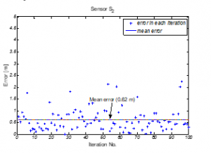
Figure 6: Positional Error from Original Position (0,75,0) for Sensor (without Gaussian noise)
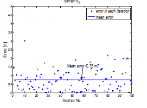
Figure 7: Positional Error from Original Position (80,40,0) for Sensor (without Gaussian noise)
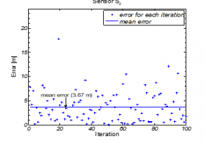
Figure 8: Positional Error from Original Position (0,75,0) for Sensor (with Gaussian noise)
Errors in determined coordinates with true Euclidean distance i.e. without Gaussian noise are almost negligible; this negligible error in turn validates the proposed mathematical model for coordinates determination with a single beacon. Besides, considering the physical sizes of the sensors deployed underwater, Figure 8 and 9 show errors (with Gaussian noise) are within acceptable range considering for a 200m water column.
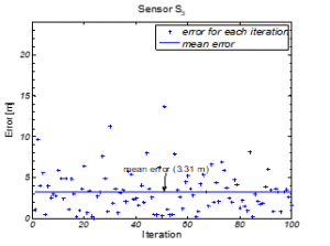
Figure 9: Positional Error from Original Position (80,40,0) for Sensor (with Gaussian noise)
For sensors with dimension 4.5x2x1.5cm, positional error 0.01-3.81cm is quite outstanding. As simulation in previous sections validates the model with the negligible error considering Euclidean distances, it is now conspicuous that the precision of the distances measured from the beacon to the deployed sensors produce lesser positional errors.
3.2. Experimental Results
A stringent experiment has been conducted in the terrestrial environments i.e. in the lab with compatible ultrasonic sensors to prove the proposed mathematical model for coordinates determination with a single beacon using Cayley-Menger determinant. It also shows that Cayley-Menger determinant could be used for non-parallel state situation with a little adjustment of the proposed model. Flight time i.e., signal’s propagation delay of the acoustic signal is used to determine the distances between the surfaced beacon and deployed submerged sensors. A beacon at the ceiling and three other sensors on the table top have been kept to achieve that same scenario as the problem domain described in previous section.
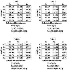
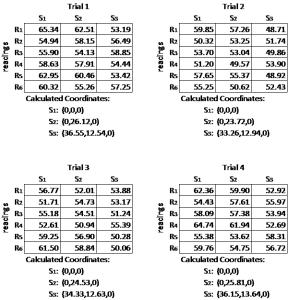
Two different scenarios with four individual tests have been conducted to validate the model. Firstly, in scenario 1 positions of the sensors are and are (0,0,0), (0,20,0), (30,15,0) respectively. Keeping the origin of the Cartesian system on sensor , positional error for sensors and are within 0.2 and 4cm range. Accuracy in distance measurements with the ultrasonic sensor generates positional error: 0.17cm, whereas in extreme case it is 3.85cm as depicted in Table 4. Secondly, in scenario 1 positions of the sensors are and are (0,0,0), (0,25,0), (35,10,0) respectively. Keeping the origin of the Cartesian system on sensor , positional error for sensor and are within 0.5 and 6cm range. Accuracy in distance measurements with the ultrasonic sensors generates positional error: 0.17cm, whereas in extreme case it is 3.85cm as illustrated in Table 5.
The ultrasonic sensors used in the experiment have 120 sentry angle; this capacity limits the movement of the surfaced sensor. Besides the built-in Arduino microseconds To Centimeter function needed to be changed to ‘double’ to acquire more precise timing as the experiment is taken place where the maximum distances between beacon and deployed sensors are less than 80cm range.
One other challenge we faced while experimenting with Arduino board is to process the generated ultrasonic pulses that are received by the sensors to calculate inter distances. As in [14], the ‘pulseIn’ function usually takes more than 20ms to process the received pulse, whereas it takes only 2.32ms to travel 80cm (approximate max distance for the experimental domain); as a result by the time it finishes pulse processing for the nearest sensor from the beacon and starts processing pulses for other sensors, it is then too late for the pulses to be on the flight. To mitigate this problem we had to generate two other 10μs pulses for rest of the two sensors in 50ms interval. So within around 100ms all three pulses are generated, this fraction of a second will have no effect on the stationary sensor nodes scenario; however, will have negligible effect in cases of mobility.
4. Conclusions
Persistent and accurate positioning is indispensable in various arenas due to necessity as well as research. As specific applications demand more accuracy and convenience, research pushes the boundary to fit and meet the demand in its own course. So, a plethora of localization algorithm has been proposed. This paper illustrates and analyzes a pragmatic approach of localization where a single node can determine deployed submerged nodes using Cayley-Menger determinant; it also portraits associated difficulties of using Cayley-Menger in non-parallel state situations in real time as the original model was designed for parallel states. In nature, parallel state situation is very rare where the plane of the beacon node and the plane of deployed sensors would be parallel. Hence, the necessity of having a pragmatic solution was conspicuous.
A solvable configuration of the domain and its associated model has been simulated to validate as well as to fathom the degree of errors. Once the distances between beacon and the deployed submerged sensors are considered to be true Euclidean, it generates negligible errors. It is also shown that the generated errors are because of erroneous distance determination; so the accuracy of coordinates solely depends on the preciseness of distance measurement method, not the model. This paper also delineates how the model could be used for non-parallel state situation with a little adjustment. Simulation results with Gaussian noise in distance measurements suggest that 0.62-3.67m error for a 200m water column is outstanding as sizes of deployed sensors or AUVs could reach few meters in length. However, mobility of the deployed sensors was not considered in this paper and left for future exploration. On the other hand, mobility of the beacon and span has very limited effect on the coordinates determination of the sensors.
To validate the simulation, a stringent experiment has been conducted in terrestrial environment. So called off-the-shelf ultrasonic sensors have been used imitating the simulated configuration. In the experiment, it has been shown that distance between beacon and deployed sensor can be calculated using acoustic signals, whereas clock synchronization could be performed using electrical signals. Mobility of the sensors was not considered in the experiment as well; however, multiple scenarios
Experimental Scenario 1: Original coordinates of sensors:
S1: (0,0,0); S2: (0,20,0); S3: (30,15,0)
Table 4: Coordinates of the Sensors and ccording to Scenario 1
Experimental Scenario 2: Original coordinates of sensors:
S1: (0,0,0); S2: (0,25,0); S3: (35,10,0)
Table 5: Coordinates of the Sensors and according to Scenario 2
and tests suggest the validity of the model. Acoustic signals are distressed by environmental variables like temperature and humidity as well as propagation speed is low compared to electrical signals. Besides, sensors that have been used in the experiment have limitations and constraints in signal processing; result indicates 0.01-3.81cm positional error for sensors with dimension 4.5x2x1.5cm is within acceptable range.
- J. H. Cui, J. Kong, M. Gerla, and S. Zhou, “The challenges of building mobile underwater wireless networks for aquatic applications,” Network, IEEE, vol. 20, pp. 12-18, 2006.
- L. Hu, B. Liu, K. Zhao, X. Meng, and F. Wang, “Research and Implementation of the Localization Algorithm Based on RSSI Technology,” Journal of Networks, vol. 9, pp. 3135-3142, 2014.
- P. Duff and H. Muller, “Autocalibration algorithm for ultrasonic location systems,” in Seventh IEEE International Symposium on Wearable Computers, 2003. Proceedings, pp. 62-68, 2003.
- E. Olson, J. Leonard, and S. Teller, “Robust range-only beacon localization,” in Autonomous Underwater Vehicles, IEEE/OES, pp. 66-75, 2004.
- J. Guevara, A. R. Jimenez, A. S. Morse, J. Fang, J. C. Prieto, and F. Seco, “Auto-localization in Local Positioning Systems: A closed-form range-only solution,” in IEEE International Symposium on Industrial Electronics (ISIE), pp. 2834-2840, 2010.
- J. C. Prieto, A. R. Jiménez, J. Guevara, J. L. Ealo, F. Seco, J. O. Roa, and F. Ramos, “Performance evaluation of 3D-LOCUS advanced acoustic LPS,” IEEE Transactions on Instrumentation and Measurement, vol. 58, pp. 2385-2395, 2009.
- A. Rahman and V. Muthukkumarasamy, “Embracing localization inaccuracy with a single beacon”, Journal ofAdvanced Computer Science and Application (IJACSA), Vol. 10 No. 12, 2019.
- A. Rahman and V. Muthukkumarasamy, , “Localization of Submerged Sensors with a Single Beacon for Non-Parallel Planes State”, in 10th International conference on Ubiquitous and Future Networks (ICUFN), pp. 525-530, 2018.
- A. Rahman, V. Muthukkumarasamy, and E. Sithirasenan, “Coordinates Determination of Submerged Sensors Using Cayley-Menger Determinant,” in Distributed Computing in Sensor Systems (DCOSS), IEEE, pp. 466-471, 2013.
- A. Rahman, V. Muthukkumarasamy, and E. Sithirasenan, “Localization of Submerged Sensors Using Radio and Acoustic Signals with Single Beacon,” in Ad-hoc, Mobile, and Wireless Network. LNCS. vol. 7960, J. Cichoń, M. Gȩbala, and M. Klonowski, Eds., ed: Springer Berlin Heidelberg, pp. 293-304, 2013.
- I. Vasilescu, K. Kotay, D. Rus, M. Dunbabin, and P. Corke, “Data collection, storage, and retrieval with an underwater sensor network,” in Proceedings of the 3rd international conference on Embedded networked sensor systems, pp. 154-165, 2005.
- J. Guevara, A. Jiménez, J. Prieto, and F. Seco, “Auto-localization algorithm for local positioning systems,” Ad Hoc Networks, vol. 10, pp. 1090-1100, 2012.
- A. Rahman, V. Muthukkumarasamy, and X. Wu, “Coordinates and Bearing of Submerged Sensors Using a Single Mobile Beacon (CSMB)”, Journal of Networks, Vol. 10 No. 8, 2015.
- P. Xie, J. H. Cui, and L. Lao, “VBF: vector-based forwarding protocol for underwater sensor networks,” Networking Technologies, Services, and Protocols; Performance of Computer and Communication Networks; Mobile and Wireless Communications Systems, pp. 1216-1221, 2006.