
Low Carbon Sustainable Building Material: Maximizing Slag Potentials for Improved Lime Mortar Mechanical Properties
Volume 5, Issue 2, Page No 786-794, 2020
Author’s Name: Sule Adeniyi Olaniyana)
View Affiliations
Department of Architecture, Ladoke Akintola University of Technology, Ogbomoso, Nigeria
a)Author to whom correspondence should be addressed. E-mail: saolaniyan@lautech.edu.ng
Adv. Sci. Technol. Eng. Syst. J. 5(2), 786-794 (2020); ![]() DOI: 10.25046/aj050299
DOI: 10.25046/aj050299
Keywords: Carbon Emissions, Climate Change, E-value, Flexibility, Lime, Mortars

Export Citations
Prior to the 19th century discovery of Portland Cement (PC), Lime Based Mortar remained popular due to its flexibility, permeability and more importantly, associated low carbon emissions. However, lime’s characteristic delayed setting/hardening time, low mechanical strength, poor internal cohesion and some volumetric changes have overshadowed significance of its outstanding features particularly, flexibility, and consequently put its overall use into decline. This study therefore aims at integrating an industrial by-product, Ground Granulated Blast Furnace Slag (slag) with lime, in form of lime-slag mortar, with a view to addressing lime shortcomings for improved performance. The methodology involved mortars with the same Binder/Aggregate (B/A) mix ratio (1:3) using five separate volumetric compositions of ‘lime-slag’ binders (i.e. 1:1, 1:2, 1:3, 2:1 and 3:1). Physical properties of the mortars involving their Water/Binder (W/B) ratios, Air Contents and Bulk Densities were recorded. Comparative evaluations of the compositions in hardened state, involving mechanical characteristics, were carried out at specific intervals through a twelve-month curing period. These were partly monitored through assessments of the composites’ microstructural behaviours over a six-month period. Results of the investigation show that addition of slag to mortars facilitate slightly larger pores with increased porosity. These effects are however minimal (i.e. from 23.42% to 25.37% porosity) when slag content is at equal volumetric content with lime. Also, at this same volumetric composition, the results show beneficial effects of slag on the composite’s mechanical properties; while the flexural strength is increased by 50%, the compressive strength is improved by about 250%. Despite the improved mechanical characteristics, the composite exhibits comparable (with lime only) capacity for deformation absorptions, thus, preserving lime’s known fundamental flexibility property. This is important for material’s durability, and overall sustainable constructions.
Received: 04 August 2018, Accepted: 16 September 2018, Published Online: 24 April 2020
1. Introduction
Climate change, growing energy costs and the impacts of human activities on the environment have become key concerns for future developments. While construction processes facilitate infrastructure developments, they equally constitute major sources of carbon dioxide production and energy consumption [1, 2] as studies show that buildings account for 30-40% of the world’s energy consumption [3, 4]. While a considerable part of this energy is commonly used to control internal microclimate conditions, other part is used to extract raw materials, transport them, make building components and, finally, to dispose of them. Therefore, interventions in this important productive sector through promotion of low-impact building materials should be encouraged [5, 6]. Thus, efforts must be directed at exploring new technical approach, capable of evolving sustainable materials for improving environmental performances of buildings [7, 8]. One such approach is renewal of interests in a partially abandoned age-long environmentally sustainable building material, lime mortar.
Lime mortar refers to a proportional mixture of lime, sand and water. It is an age-long building material [9-11]. It is a plastic material that is slow to harden but allows movements within the mortar joints, without compromising its structural stability. Lime mortar has also been shown to exhibit great permeability, which enables it to reduce moisture entrapment, a phenomenon known as “breathability” [12-15]. Greater environmental awareness of its advantages in terms of carbon dioxide emissions during manufacture (20% less than that of cement) and subsequent adsorption during carbonation promotes its use [13, 16, 17]. However, Lime Mortars are associated with exaggeratedly long setting and hardening periods, low internal cohesion, relatively low mechanical strengths and some volumetric changes, among others [18-23]. These, coupled with the absence of rigorous studies about their characteristics and properties (among others) resulted in its relative disuse. The study therefore sought to revive this age-long building material through integration of an industrial by-product, ‘Ground Granulated Blast Furnace Slag’ (slag), in form of a composite material, by formulating lime based blended mortars with varying proportions of slag.
Slag is a granular glassy amorphous waste material, formed as a by-product from production of steel and iron. It is obtained when the liquid slag, created at 1350–1500°C is cooled quickly using water, to produce granules or pellets which have hydraulic cementing properties when finely ground [24-28]. It is whitish, essentially of silicates and aluminosilicates of calcium and other oxides with main inorganic constituents such as silica (30–35%), calcium oxide (28–35%), magnesium oxide (1–6%), and Al2O3/Fe2O3 (18–258%). The specific gravity of the slag is approximately 2.90 with its bulk density varying in the range of 1200–1300 kg/m3 [27, 29-31]. Slag is widely used as a construction material due to its latent cementitious property when mixing with lime, alkali-hydroxides or Portland cement [32-36]. In some cases, it has been used as a successful replacement material for Portland cement, improving some properties [37, 38] and bringing environmental and economic benefits (such as low heat of hydration, long term strength, resistance to acid, better durability and general cost saving measure), to the cement industries [39-42]. It has also been used as a supplementary cementitious material for production of blended cement and slag cement. Recent advancements in Slag utilisation, as an alternative binding material in concrete production indicate its possible blend with lime, for improved lime mortar performance. Utilisation of slag in this area has significant environmental benefits (with least CO2 emission to the atmosphere during this process) [43, 44]. Its production requires less energy than the production of Portland cement as slag generation is about 10% of the total steel production. Also, the requirement to recycle industrial wastes and by-products, rather than landfilling this potentially valuable material makes its integration acceptable [45-47]. Its potential re-use as a constituent in blended lime mortar would add to solve the associated problem related to its disposal [44, 48, 49]. Thus, this study aims at integrating this important industrial by-product, Ground Granulated Blast Furnace Slag (slag) with lime, in form of lime-slag mortar, with a view to addressing lime shortcomings for improved performance. In effect, using the binders’ varying compositions, effects of lime partial substitution by slag in the evolving lime-slag mortars would be useful. This would attempt to synergise individual qualities of the constituents as the resulting composite would be characterized by faster setting and hardening, than lime, with overall improvements on their applications [50-52]. Through this attempt, growing interests in reviving sustainable lime based materials particularly mortar, would be enhanced..
2. Experimental Procedure
2.1. Materials and mortar Preparation
Commercially available Natural Hydraulic Lime of the class NHL-5.0 (St Astiers, UK), characterised with the lime’s highest compressive strength, based on the 28-day test (BSI, 2010a) [53] was adopted for this research. The selection of lime class was based on its relatively short setting time for optimal strength yield, its availability, ease of handling, as well as the need to maximise lime performance behaviour [2, 54]. Lime’s average Particle Size Distribution shown in Table 1 indicates particles with main equivalent diameter of 33.99 µm (by volume) and 10.19 µm (by Surface Area). 90% of these particles have sizes below 91.88 µm (by volume). Lime’s chemical compositions (by elements) determined by Energy Dispersive Spectrometry are given in Table 2. Ground granulated blast furnace slag (slag) for this investigation was obtained from ‘Hanson Cement’, United Kingdom. Its average Particle Size Distribution shown in Table 1 indicates particles with main equivalent diameter of 25.50µm (by volume) and 11.20µm (by Surface Area). 90% of these particles have sizes below 49.78µm (by volume). Slag’s chemical compositions (by elements) are given in Table 2. Commercially available siliceous fine kiln dried sand, obtained from Fife Silica Sands (a division of Patersons of Greenoackhill Ltd, United Kingdom) constituted the aggregates. The aggregate was passed through a sieve analysis in accordance with the requirements of (BSI, 2013) [55], and the particle size distributions in compliance with ASTM C 136 (ASTM, 2014) [56] are shown in Figure 1. The sand had Particle Size Distribution of 0-2 mm (i.e. 0.05 mm < Ø < 2 mm). The suitability of the gradation of the tested aggregates as mortar aggregates was evaluated by comparing the obtained gradation curve with the suggested particle size ranges of ASTM C 33 (ASTM, 2016) [57]. The results indicate that the sand has a suitable grading but with slightly lower particle sizes.
Table 1. Particle Size Diameters of the tested materials
|
Parameters |
d(v,0.5) |
d(v,0.1) |
Mode |
d(v,0.9) |
D[4,3] (main equivalent diameter by volume) |
D[3,2] (main equivalent diameter by Surface Area) |
|
|
Specified Particle Diameter (µm) |
Lime
|
10.78 | 5.28 | 6.50 | 91.88 | 33.99 | 10.19 |
| Slag | 19.60 | 5.54 | 15.17 | 49.78 | 25.50 | 11.20 | |
Table 2. Chemical Composition of the materials
|
Material |
Elemental Chemical Composition of the materials (by % weight of the dry specimen) | |||||||||||
| Ca | O | Si | C | Sb | Al | Fe | Mg | S | K | Na | Ti | |
| Lime | 47.6 | 37.6 | 5.2 | 4.4 | 3.3 | 0.7 | 0.5 | 0.5 | 0.2 | – | – | – |
| Slag | 26.5 | 39.6 | 13.0 | 9.3 | – | 5.5 | – | 4.4 | 1.0 | 0.4 | 0.3 | – |
| Sand | 0.2 | 53.5 | 43.0 | – | – | 1.6 | 0.4 | – | – | 1.1 | 0.2 | |

Figure 1: Grain size distribution of the aggregate
The mortars were prepared in accordance with the required standard (BSI, 2000). The binder-aggregate (B/A) ratio was maintained at 1:3 by volume, chosen from the commonest dosage reported in the literature [23, 58-60]. Volume proportions of components were converted to weights, to avoid measurement imprecision during batching processes (Hanley and Pavia, 2008). Mortar mixtures were prepared using the correct amount of water required to obtain adopted workability of 145±5 mm (measured by the flow table test – BS EN 1015-3 (BSI, 2000) [61] as BS EN 1015-6 (BSI, 1999a) [62] specifies a flow value of ‘140-200 mm’ for ‘plastic mortar’. Arising from visual and physical assessments of the mixes during the trial experimentation however, a flow value of 140 – 150mm (i.e. 145+5mm) was adopted. As observed, either higher or lower value tends towards stiffness or fluidity respectively. This was determined in accordance with (BSI, 2005) [63]
Using the stated B/A ratio (i.e. 1:3), each mortar formulation was prepared with progressively increasing/decreasing slag contents as indicated in Table 3. Mixing was done in the laboratory mixer of 30 litres maximum capacity. The mixing procedure was performed in a number of stages: Aggregates were placed first, followed by other dry materials (i.e. lime and slag, pre-mixed earlier, where applicable) and these were blended consistently for 60 seconds as best practice dictates that the NHL powder should be thoroughly mixed through the dry sand, ensuring batch colour consistency prior to gradually adding water. Water was added slowly during 30 seconds and mixing continued for another 30 seconds. Mixing was stopped for 90 seconds as mortar adhering to the wall and bottom of the mixer bowl was scraped off. Mixing then resumed to obtain consistent mixture. The entire mixing period lasted about 5minutes. For every mortar mix, minimum of three prismatic specimens of 40×40×160 mm were prepared, the average value of which represented the ‘actual value’ for consideration during the specimen evaluations afterwards (i.e. for microstructural analysis, and mechanical characteristics evaluations: Flexural and Compressive tests; Moduli of Elasticity determination). The specimens were compacted with a vibration table after mould filling in prismatic casts (BSI, 2010b) [64], removed from the moulds 2 days later and left to cure at the laboratory ambient conditions of 21+4ºC (temperature) and 40+5% (relative humidity), until the test dates of 1, 3, 6, 9 and 12 months.
2.2. Analytical methodology
2.2.1. Microstructural Characteristics
Microstructural characteristics of the mortar samples were evaluated in terms of the total porosity (in %), median pore diameter (by volume in nm), bulk density and pore size distribution, using Mercury Intrusion Porosimetry (MIP) technique. This was achieved with AutoPore IV 9500 by Micrometrics (with pressure range up to 60000 psi). The test was carried out with samples of approximately 1.5g that were extracted from the core of the crushed prisms. Under short term loading and at a relatively low rate of load application (approximately 2mm/min), the chance of micro crack propagation is minimum [60, 65]. These samples were obtained at the test ages of one and six months, and dried in an oven at temperature of 75 ± 1 ºC for 24 hours before the test, to ensure that the sample is devoid of moisture contents (which may otherwise affect its microstructural properties, thereby affecting the results).
2.2.2. Mechanical properties
The mechanical properties were evaluated with regard to the three-point flexural tests, and compressive strength. While the flexural strength tests were performed on the ELE AutoTest 2000 apparatus with a load application pace of 50 N/s, compressive strength tests were conducted on the two fragments of each specimen (resulting from the preceding flexural test) using INSTRON 3367 with 30kN load capacity, moving at a loading rate of 2mm/min. The results reported in this work were all taken as an average value of six similar specimen fragments. Additionally, INSTRON 3367 plots stress/strain graph on the screen, with the value for Modulus of Elasticity generated automatically. In generating the modulus output, the system algorithm determines the slope of the stress/strain curve in the initial linear portion of the curve. It calculates the slopes using least-squares fit on test data for a specified number of regions between the lower and upper bounds, and reports the steepest slope as the modulus. The algorithm will not calculate a result if the data does not contain either the specified upper or lower bound, and the data contains the same number or fewer points than the specified number of regions.
Table 3. Lime-Slag Mortars’ Compositions by materials
|
Slag Contents |
Mortar Reference I.D. (Slag Contents) |
Volumetric Ratio (L-Sl-Sd) |
Lime (L): Volume (Volume in ‘ml’/ mass in ‘g’) |
Slag (Sl): Volume (Volume in ‘ml’/ mass in ‘g’) |
Sand (Sd): Volume (Volume in ‘ml’/ mass in ‘g’) |
|
0% |
L13 (0%) |
1-0-3
|
1 (1700/ 1172) |
0 (0/ 0) |
3 (4350/ 6444) |
|
25%
|
LS31 (25%) |
3-1-12 |
3 (770/ 528) |
1 (420/ 363) |
12 (4350/ 6444) |
|
33%
|
LS21 (33%) |
2-1-9 |
2 (665/ 458) |
1 (550/ 472) |
9 (4240/ 6283) |
|
50% |
LS11 (50%) |
1-1-6 |
1 (850/ 586) |
1 (850/ 725) |
6 (4350/ 6444) |
|
66%
|
LS12 (66%) |
1-2-9 |
1 (510/ 352) |
2 (1000/ 870) |
9 (3920/ 5800) |
|
75%
|
LS13 (75%) |
1-3-12 |
1 (260/ 176) |
3 (1260/ 1088) |
12 (4350/ 6444) |
2.2.3. Other Preliminary Material Testing
Some preliminary material testing were also carried out as follows:
- Application of Scanning Electron Microscopy/Energy Dispersive X-ray Spectrometry using ‘Carl Zeiss EVO 50’ Scanning Electron Microscope was employed for examination and analysis of the microstructure, morphology and chemical composition characterizations of the experimental materials (Lime and slag);
- Application of Laser Difractometry Xmastersize with air dispersion was adopted for determination of the Pore Size Distribution of the tested materials (Lime and slag);
- Consistency of fresh mortars was examined using the flow table test in accordance with (BSI, 2000) [61];
- Bulk Density of Fresh Mortar was determinined accordance with (BSI, 1999a) [62], and;
- Air content of fresh mortars was determined by the pressure method using Air Entrainment Meter in accordance with (BSI, 1999b) [66].
3. Results and Discussion
3.1. Physical Characteristics
Table 4 shows the results of the W/B ratios, Air Contents and Bulk Densities obtained for lime, and lime-slag mortars using varying binders’ contents. For lime only (0% slag content, i.e. L13), Table 4 indicates a W/B ratio of 1.53, Air Contents of 6.4 and Bulk Density of 1.93g/ml. Addition of slag content below 50% of the binders resulted in higher water demand. This may be attributed to the higher lime content and its high water demand. However, at equal lime-slag content (LS11), a reduction in W/B ratio was observed, due to reduced lime content. Further slag addition (above 50%) resulted in subsequent rising water demand relative to LS11. This may be a consequence of higher slag content and hence higher degree of hydration relative to hydraulic lime hydration and carbonation [67, 68]. With progressive addition of slag to the mortar, there is a general increase in the air contents for the composites. This may be related to slag’s higher degree of hydration and subsequent formation of air spaces arising from consumption of initial kneading water. Progressive addition of slag to the mortar increased the bulk densities, though not in a linear trend. These increments may be related to the rising water demand to obtain pastes of same consistency and subsequent deposition of the hydration products. Hence, the higher the slag content, the higher the resulting bulk density.
3.2. Microstructural features
Figs. 2(a) and (b) show the Pore Size Distribution (PSD) curves obtained by Mercury Intrusion Porosimetry (MIP) for the six different composites at 1 and 6 months of curing.
For lime only, at 1 month of curing, the graph indicates a bimodal PSD with predominant sizes between (0.5 µm – 5 µm) and (5 µm – 20 µm), as shown in Fig. 2(a). In this case, the mortar exhibits both gel pore (i.e. 1 nm – 3 µm) and substantial proportion of capillary pores (i.e. 3 – 30 µm). These large pores result from loss of excess unbound kneading water due to strong water-retaining characteristic of lime and its associated slow carbonation process. After 6 months, in spite of the continuous hydration and carbonation processes, the median pore diameter increased (from 2.16 µm to 3.96 µm) (Table 5), indicating more presence of larger pores (i.e. between 0.5 µm and 40 µm)with the shift of the PSD curves to the left (Fig. 2(b)).
Table 4: Lime-Cement Mortars’ Compositions by materials and Water/Binder ratios.
|
Slag Contents |
Mortar Reference I.D.
|
Water/ Binder Ratio
|
Air Content (%)
|
Bulk Density (g/ml)
|
| 0% | L13 | 1.53 | 6.4 |
1.93 |
|
25%
|
LS31 | 2.05 | 6.1 |
1.98 |
|
33%
|
LS21 | 1.91 | 6.5 |
2.01 |
| 50% | LS11 | 1.29 | 9.2 |
2.05 |
|
66%
|
LS12 | 1.35 |
8.4 |
2.05 |
|
75%
|
LS13 | 1.42 |
8.3 |
2.06 |
However, a reduction is observed in the total pore volume (i.e. from 27.77% to 23.42%), which indicates filling of some of the capillary voids due to deposition of the hydration and carbonation products (from hydraulic lime). The bulk density was reduced (from 1.75 g/ml to 1.72 g/ml) due to evaporation of excess kneading water and subsequent associated drying shrinkage.
Progressive addition of slag to the mortar resulted in similar patterns of PSD relative to lime mortar (i.e. bimodal distributions, between 0.6 µm – 6.5 µm, and 5 µm – 10.5 µm pore ranges) at 1 month curing. The only exception is LS13 with a wide distribution across, having additional identifiable pore sizes at both 13 nm and 40 µm pore diameters (Figure 2(a)). Porosities of the composites also reduced with LS13 recording the highest value of 11% reduction (compared with lime only). At 6 months, the bimodal patterns of the curves still remained, with distinctive two pore size ranges at 1 µm – 4 µm and 4.5 µm – 10.5 µm (Fig. 2(b)). Progressive hydrations in the composites were also noticed with higher bulk densities (Table 5). However, all mortars had their individual median pore diameters increased. This could be a consequence of fine cracks formation due to autogenous deformation [32, 69]. Composite with the highest slag content (LS13) had a dominance of large pores with 6 µm pore size diameter which may have a negative impact on compressive strength. Compared to lime mortar, porosities of the composites are higher at 6 months. This probably accounts for more CO2 penetration for carbonation reactions. The above results indicate progressive addition of slag to mortars could facilitate slightly larger pores with increased porosity. These effects are however minimal (i.e. from 23.42% to 25.37% porosity) when slag content is at equal volumetric content with lime.
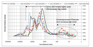
Figure 2 (a): At 1 month

Figure 2 (b): At 6 months
Figure 2: Pore size distribution of lime mortars with increasing slag contents
3.3. Mechanical Properties
The results obtained for three mechanical parameters – flexural strength, compressive strength and modulus of elasticity, over a 12-month curing period are as summarised in Figures 3 – 5. Each result was taken as an average value of three similar specimens for flexural strength and five similar specimens for both compressive strength and modulus of elasticity. The coefficients of variation (COV) fall substantially within the lower range (0 – 15%). This suggests consistent results. However, there were also few cases of higher COV, which indicate some degree of scatter in those cases. Appropriate error bars are also displayed on the respective graphs. Fig. 3 illustrates the results of the Flexural Strengths obtained for lime and lime-slag mortars using varying binders’ contents.

Figure 3. Flexural Strength developments for Lime Mortars with increasing slag contents
Table 5. Extracted Mercury Intrusion Porosimetry data for Lime-Slag mortars containing increasing slag contents
|
Specimen Reference I.D. |
Curing Period |
Median Pore Diameter (Volume) [nm] |
Bulk Density at 0.52 psia [g/mL] |
Porosity [%] |
|
L13 (0%) |
1 Month | 2163.6 | 1.75 | 27.77 |
| 6 Months | 3955.0 | 1.72 | 23.42 | |
|
LS31 (25%) |
1 Month | 5762.2 | 1.74 | 31.57 |
| 6 Months | 8599.5 | 1.79 | 23.71 | |
|
LS21 (33%) |
1 Month | 4358.6 | 1.73 | 29.12 |
| 6 Months | 4840.3 | 1.75 | 29.87 | |
|
LS11 (50%) |
1 Month | 2183.6 | 1.83 | 27.17 |
| 6 Months | 2495.2 | 1.85 | 25.37 | |
|
LS12 (66%) |
1 Month | 2522.0 | 1.81 | 27.64 |
| 6 Months | 2678.9 | 1.88 | 27.15 | |
|
LS13 (75%) |
1 Month | 3027.1 | 1.86 | 24.85 |
| 6 Months | 3576.8 | 1.82 | 28.84 |
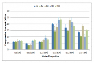
Figure 4. Compressive Strength developments for Lime Mortars with increasing slag contents
For lime only, Fig. 3 shows a flexural strength value of 0.70 MPa in the first month of curing which decreased to 0.61 MPa at the end of 12 months. This may be due to formation of different pore sizes (bimodal PSD between (0.5 – 5 µm) and (5 – 20 µm)) resulting from loss of excess unbound kneading water as explained earlier. Progressive addition of slag (up to 50% of binders’ content, i.e. LS11) to the mortar translates to the corresponding increase in the flexural strength (about 50%), though not in a linear trend. This may be related to high degree of slag hydration as evidenced by an increase in the composite bulk density (i.e. 1.85 g/mL for LS11, compared with 1.72 g/mL for L13) as well as decrease in the median pore diameter (i.e. 2.5 µm for LS11, compared with 4.0 µm for L13) over the same curing period. However, further slag addition (beyond 50%) resulted in subsequent reduction in the flexural strength. In this case, slag exhibited higher hydration as the mortar exhibited more self-dessication. This agrees with the results of the microstructural analysis which show increasing median pore diameters and higher porosities. This may be connected with the formation of fine cracks arising from autogenous deformation usually associated with slag hydration [70, 71]. These results therefore show beneficial effect of slag on composite’s flexural strength at equal lime-slag content as further addition may impact negatively on the flexural strength.
Results of compressive strength followed a similar pattern to flexural strength. Figure 4 shows a marginal increase in the strength of the mix containing lime only from 0.61 MPa to 0.66 MPa at 1 month and 12-month curing respectively. This may be a consequence of high W/B ratio and slow carbonation rate of lime.
Progressive addition of slag up to 50% to the mortar content results in about 250% increase in the compressive strength, (though not in a linear trend as slag content increased). This may be due to higher slag hydration relative to hydraulic lime. However, further increment of slag content induces an increased dessication of slag, which in turn leads to formation of matrixes with higher median pore diameters and higher porosities. This possibly culminated in the formation of fine cracks and subsequent lower compressive strengths recorded. Thus, the results show beneficial effect of slag on composite’s compressive strength at equal lime-slag content as further addition may impact negatively on the strength.
Compressive strengths recorded above are related to the mortars’ practical performances. These are reflected in their moduli of elasticity (E) as shown in Figure 5.

Figure 5. Moduli of Elasticity (E) values for Lime Mortars with increasing slag contents
From Figure 5, LS11 with highest compressive strength had the highest ‘E’ value at the 12th month of curing. This is against L13 which had the lowest compressive strength at the same time. Both LI3 and LS11 have tendencies to exhibit interesting elastic behaviours as demonstrated in their stress-strain relationships at 1 and 12-month curing (Figures 6(a) and (b)), with varying capacities to absorp deformations. However, L13 with low compressive strength (low E-value) has higher capacity for deformation absorption relative to LS11.
From Figures 6(a) and (b), despite increased mechanical strengths of LS11, it is still able to exhibit capacities for deformation absorptions (compared with lime only). This characteristic feature therefore illustrates beneficial effect of slag on composite’s compressive strength at equal lime-slag volumetric content.

Figure 6: Compressive Strength versus Strain relationships for lime and lime-slag mortars
4. Conclusions
The study reflects performance assessments of lime-slag composites with progressive addition of slag. It can be inferred therefrom, that addition of slag has significant impacts on lime mortar performance particularly, with regard to mechanical strength developments. At equal lime-slag volumetric composition, beneficial impact of slag on the mechanical behaviour of the composite could be obtained. This impact is a reflection of the microstructural behaviour of the composites, which in turn defines the mortar performance. Thus, performance of low-impact sustainable building materials such as lime may be enhanced, and its revival may be encouraged in form of lime-slag composites, for improved energy consumption and environmental performances of buildings, as demonstrated in this study.
Conflict of Interest
The author declares no conflict of interest.
Acknowledgment
The authors gratefully acknowledge the financial supports from ‘TETFUND AST&D’ Scheme, an educational development organ of The Federal Government of Nigeria. Thanks are also due to Hanson Cement, United Kingdom, for the provision of the slag used for this work.
- Ciancio, D., Beckett, C. T. S., and Carraro, J. A. H. (2014). Optimum lime content identification for lime-stabilised rammed earth. Construction and Building Materials, 53, 59-65.
- Olaniyan, S.A. (2017). Sustainable Lime Based Mortars: Performance Assessment of Composites for Building Construction. PhD Thesis, Glasgow Caledonian University, Glasgow, Scotland (UK).
- Roberto De Lieto Vollaro, Calvesi, M., Battista, G., Evangelisti, L., Gori, P., and Guattari, C. (2013). A new method of technical analysis to optimise the design of low impact energy systems for buildings. International Journal of Engineering and Technology Innovation, 3(4), 241-250.
- Fumo, N. (2014). A review on the basics of building energy estimation. Renewable and Sustainable Energy Reviews, 31, 53-60.
- Olaniyan, S.A., and Klemm, A. J. (2015). Current trends in development of lime based composites. Building Physics in Theory and Practice, VII (3), 49-54.
- Harish, V. S. K. V., and Kumar, A. (2016). A review on modeling and simulation of building energy systems. Renewable and Sustainable Energy Reviews, 56, 1272-1292.
- Klemm, A. J., and Sikora, K. S. (2013). The effect of superabsorbent polymers (SAP) on microstructure and mechanical properties of fly ash cementitious mortars, Construction and Building Materials, 49, 134-143.
- Goldstein, D. B., and Eley, C. (2014). A classification of building energy performance indices. Energy Efficiency, 7(2), 353-375.
- Lanas, J., Pérez Bernal, J. L., Bello, M. a., and Alvarez Galindo, J. I. (2004). Mechanical properties of natural hydraulic lime-based mortars. Cement and Concrete Research, 34(12), 2191–2201.
- Arandigoyen, M., and Alvarez, J. I. (2007). Pore structure and mechanical properties of cement–lime mortars, Cement and Concrete Research, 37(5), 767-775.
- Hughes, J., Lindqvist, J. E., CBI Betonginstitutet AB, SP – Sveriges Tekniska Forskningsinstitut, and RISE. (2012). RILEM TC 203-RHM: Repair mortars for historic masonry: The role of mortar in masonry: An introduction to requirements for the design of repair mortars, Materials and Structures, 45(9), 1287-1294.
- Banfill, P. F. G. (1994). Rheological methods for assessing the flow properties of mortar and related materials. Construction and Building Materials, 8(1), 43-50.
- Mcdonald, L. (2000). Hydraulic lime mortar for the house of the future, The Structural Engineer, 78 (7).
- Forster, A.M., (2002). An assessment of the relationship between the water vapour permeability and hydraulicity of lime based mortars with particular reference to building conservation materials science. PhD Thesis, Heriot-Watt University, Edinburgh.
- Solak, A. (2016). Experimental investigation of lime mortar used in historical buildings in becin, turkey. Materials Science, 22(1), 105-112.
- Edwards A.J. (2005) Properties of Hydraulic and Non-hydraulic Limes for Use in Construction. PhD Thesis, Napier University, Edinburgh.
- Ball, R. J., El-Turki, A., Allen, W. J., Nicholson, J. A., and Allen, G. C. (2009). Deformation of NHL3.5 and CL90/PC hybrid mortars. Proceedings of the Institution of Civil Engineers – Construction Materials, 162(1), 29-35.
- Hughes, J. J. and Valek, J. (2003). Mortars in Historic Buildings: A Review of the Conservation, Technical and Scientific Literature. Historic Scotland, & Historic Scotland, Technical Conservation, Research and Education Division. Edinburgh: Historic Scotland.
- Olaniyan, S.A., Klemm, A.J. and Almeida, F.C. (2016). Evolving Low Carbon Sustainable Building Material: Making Case for Cement-Lime Composites. 9th International Concrete Conference on Environment, Efficiency and Economic Challenges for Concrete, Dundee.
- Pacheco-Torgal, F., Castro-Gomes, J., and Jalali, S. (2008). Alkali-activated binders: A review: Part 1. Historical background, terminology, reaction mechanisms and hydration products. Construction and Building Materials, 22(7), 1305.
- Izaguirre, A., Lanas, J., and Alvarez, J. I. (2011). Effect of a polypropylene fibre on the behaviour of aerial lime-based mortars. Construction and Building Materials, 25(2), 992-1000.
- Forster, A. M., and Carter, K. (2011). A framework for specifying natural hydraulic lime mortars for masonry construction. Structural Survey, 29(5), 373-396.
- Ventola, L., Vendrell, M., and Giraldez, P. (2013). Newly-designed traditional lime mortar with a phase change material as an additive. Construction and Building Materials, 47, 1210-1216.
- Taylor G.D. (1983) Materials of Construction. New York: Longman Inc.
- Song, S., Sohn, D., Jennings, H. M., and Mason, T. O. (2000). Hydration of alkali-activated ground granulated blast furnace slag. Journal of Materials Science, 35(1), 249-257.
- Richardson, J. M., Biernacki, J. J., Stutzman, P. E., and Bentz, D. P. (2002). Stoichiometry of slag hydration with calcium hydroxide. Journal of the American Ceramic Society, 85(4), 947-953.
- Kumar, R., Kumar, S., Badjena, S., and Mehrotra, S. P. (2005). Hydration of mechanically activated granulated blast furnace slag. Metallurgical and Materials Transactions B, 36(6), 873-883.
- Juenger, M. C. G., Monteiro, P. J. M., and Gartner, E. M. (2006). In situ imaging of ground granulated blast furnace slag hydration. Journal of Materials Science, 41(21), 7074-7081.
- Das, B., Prakash, S., Reddy, P.S.R. and Misra, V.N. (2007). An overview of utilization of slag and sludge from steel industries. Resources Conservation and Recycling, 50, 40–57.
- Bellmann, F. and Stark, J. (2009) Activation of Blast Furnace Slag by a New Method. Cement and Concrete Research 39, 644–650
- Chi, M., Liu, Y., and Huang, R. (2015). Mechanical and microstructural characterization of alkali-activated materials based on fly ash and slag. International Journal of Engineering and Technology, 7(1), 59-64.
- Chen, W., and Brouwers, H. J. (2007). The hydration of slag, part 1: reaction models for alkali-activated slag. Journal of Materials Science, 42(2), 428-443. Doi: 10.1007/s10853-006-0873-2.
- Haha, M. B., Lothenbach, B., Le Saout, G., and Winnefeld, F. (2011). Influence of slag chemistry on the hydration of alkali-activated blast-furnace slag — part I: Effect of MgO. Cement and Concrete Research, 41(9), 955-963.
- Wang, Q., Yan, P., and Han, S. (2011). The influence of steel slag on the hydration of cement during the hydration process of complex binder. Science China Technological Sciences, 54(2), 388-394.
- Provis, J. L., Myers, R. J., White, C. E., Rose, V., and van Deventer, J. S. J. (2012). X-ray microtomography shows pore structure and tortuosity in alkali-activated binders. Cement and Concrete Research, 42(6), 855-864.
- Tan, Z., De Schutter, G., Ye, G., Gao, Y., and Machiels, L. (2014). Influence of particle size on the early hydration of slag particle activated by ca solution. Construction and Building Materials, 52, 488.
- Escalantea, J.I., Gomez, L.Y., Johalb, K.K., Mendozaa, G., Manchaa, H., and Mendez, J. (2001) Reactivity of Blast-Furnace Slag in Portland cement Blends Hydrated under Different Conditions. Cement and Concrete Research 31, 1403–1409.
- Rashad, A. M., and Khalil, M. H. (2013). A preliminary study of alkali-activated slag blended with silica fume under the effect of thermal loads and thermal shock cycles. Construction and Building Materials, 40, 522-532;
- Hooton, R. D. (2000). Canadian use of ground granulated blast-furnace slag as a supplementary cementing material for enhanced performance of concrete. Canadian Journal of Civil Engineering, 27(4), 754-760.
- Gruskovnjak, A., Lothenbach, B., Winnefeld, F., Figi, R., Ko, S.-C., Adler, M., and Mäder, U. (2008) Hydration Mechanisms of Super Sulphated Slag Cement. Cement and Concrete Research 38, 983–992.
- Bernal, S. A., Provis, J. L., and Green, D. J. (2014). Durability of Alkali-Activated materials: Progress and perspectives. Journal of the American Ceramic Society, 97(4), 997-1008.
- Yao, X., Yang, T., and Zhang, Z. (2016). Compressive strength development and shrinkage of alkali-activated fly ash–slag blends associated with efflorescence. Materials and Structures, 49(7), 2907-2918.
- Dubrawski, J.V. (1997) Thermal Characteristics of Aged Granulated Blast Furnace Slags. Journal of Thermal Analysis, 48, 63-72.
- Aydın, S., & Baradan, B. (2014). Effect of activator type and content on properties of alkali-activated slag mortars. Composites Part B: Engineering, 57, 166-172.
- Wu, X., Roy, D.M., and Langton, C.A. (1983). Early stage hydration of slag-cement. Cement and Concrete Research, 13, 277-286.
- Shi, C., and Qian, J. (2000). High performance cementing materials from industrial slags — a review. Resources Conservation and Recycling, 29(3), 195-207.
- Provis, J. L. (2014). Geopolymers and other alkali activated materials: Why, how, and what? Materials and Structures, 47(1), 11-25.
- Nicolas, R. e., and Provis, J. L. (2015). The interfacial transition zone in alkali-activated slag mortars. Frontiers in Materials, 2.
- Ye, H., and Radlińska, A. (2016). Shrinkage mechanisms of alkali-activated slag. Cement and Concrete Research, 88, 126-135.
- Lanas, J., Pérez Bernal, J. L., Bello, M. a., and Alvarez Galindo, J. I. (2004). Mechanical properties of natural hydraulic lime-based mortars. Cement and Concrete Research, 34(12), 2191–2201.
- Sébaı̈bi, Y., Dheilly, R. M., and Quéneudec, M. (2004). A study of the viscosity of lime–cement paste: Influence of the physico-chemical characteristics of lime. Construction and Building Materials, 18(9), 653-660.
- Hossain, M. M., Karim, M. R., Hossain, M. K., Islam, M. N., and Zain, M. F. M. (2015). Durability of mortar and concrete containing alkali-activated binder with pozzolans: A review. Construction and Building Materials, 93, 95-109.
- British Standards Institution (BSI) (2010a) BS EN 998: Masonry Mortar – Part 2: Specification for Mortar for Masonry.
- Moropoulou, A. (2005) Reverse engineering: a proper methodology for compatible restoration mortars. RILEM Conference Proceedings on Historic Mortars, Delft.
- British Standards Institution (BSI) (2013) BS EN 13139: Aggregates for mortar – Part 3 (PD 6682): Guidance on the use of BS EN 13139.
- ASTM C136 (2014) Standard Test Method for particle size distributions
- ASTM C 33 (ASTM, 2016) Standard Specification for mortar Aggregates
- Moropoulou, A., Cakmak, A. S., Biscontin, G., Bakolas, A., and Zendri, E. (2002). Advanced byzantine cement based composites resisting earthquake stresses: The crushed brick/lime mortars of justinian’s hagia Sophia. Construction and Building Materials, 16(8), 543-552.
- Lanas, J., and Alvarez-Galindo, J. I. (2003). Masonry repair lime-based mortars: Factors affecting the mechanical behaviour. Cement and Concrete Research, 33(11), 1867-1876.
- Mosquera, M.J., Silva, B., Prieto, B., and Ruiz-Herrera, E. (2006) Addition of cement to lime-based mortars: effect on pore structure and vapor transport. Cement and Concrete Research 36, 1635– 1642.
- British Standards Institution (BSI) (2000) BS EN 1015: Methods of Test for Mortar for Masonry – Part 3: Determination of Consistence of Fresh Mortar (by Flow Table).
- British Standards Institution (BSI) (1999a) BS EN 1015: Methods of Test for Mortar for Masonry – Part 6: Determination of Bulk Density of Fresh Mortar.
- British Standards Institution (BSI) (2005) PD 6678: Published Document – Guide to the Specification of the Masonry Mortar.
- British Standards Institution (BSI) (2010b). BS EN 459: Building Lime – Part 2: Test Method.
- Pozo-Antonio, J. S. (2015). Evolution of mechanical properties and drying shrinkage in lime-based and lime cement-based mortars with pure limestone aggregate. Construction and Building Materials, 77, 472-478.
- British Standards Institution (BSI) (1999b) BS EN 1015: Methods of Test for Mortar for Masonry – Part 7: Determination of Air content of Fresh Mortar.
- Chi, M., and and Huang, R. (2013). Binding mechanism and properties of alkali-activated fly ash/slag mortars. Construction and Building Materials, 40, 291-298.
- Geng, H., and Li, Q. (2014). Development of microstructure and chemical composition of hydration products of slag activated by ordinary portland cement. Materials Characterization, 87, 149.
- Bernal, S.A., Provis, J.L, Rose, V, Mej ́ıa de Guti´errez, R. (2013). High-resolution X-ray diffraction and fluorescence microscopy characterization of alkali-activated slag-metakaolin binders. Journal of the American Ceramic Society, 96, 1951–57.
- Burciaga-Díaz, O., Díaz-Guillén, M.R., Fuentes, A.F. and Escalante-Garcia, J.I. (2013) Mortars of alkali-activated blast furnace slag with high aggregate: binder ratios. Construction and Building Materials, 44, 607–614.
- Biernacki, J. J., Richardson, J. M., Stutzman, P. E., and & Bentz, D. P. (2002). Kinetics of slag hydration in the presence of calcium hydroxide. Journal of the American Ceramic Society, 85(9), 2261-2267.