
Seismic Performance of Infilled Reinforced Concrete Buildings
Volume 5, Issue 2, Page No 711-717, 2020
Author’s Name: Miloud Mouzzouna), Abdelkader Cherrabi
View Affiliations
Department of civil engineering, Hassania School of Public Works, Morocco
a)Author to whom correspondence should be addressed. E-mail: mouzzoun.mouloud@gmail.com
Adv. Sci. Technol. Eng. Syst. J. 5(2), 711-717 (2020); ![]() DOI: 10.25046/aj050288
DOI: 10.25046/aj050288
Keywords: Seismic, Building, Strut, Reinforced, SAP2000, Concrete

Export Citations
In the Moroccan seismic code, infill walls are considered as secondary elements and their lateral strength and stiffness are neglected in the design when considering horizontal seismic loads. In this article we propose to investigate the effect of infill on the seismic performance of the buildings. A 6-stories reinforced concrete frame building is investigated. The concept of equivalent strut is used for infill panel. Diagonal strut carries only compression forces. Strut properties are calculated according to the FEMA306.Software analysis SAP2000 is used to conduct numerical simulations. Numerical results show that there is a change in the internal forces, in the fundamental period of vibration and in the lateral story drift when masonry infill is included in the design. Seismic behavior of infill frame is different from that predicted by bare frame.
Received: 10 January 2020, Accepted: 31 March 2020, Published Online: 20 April 2020
1. Introduction
Earthquakes occurred recently in the world, Northridge1994, Kobe 1995, Izmit1999 and Alhoceima2004, have shown that presence of masonry infill walls interact with the surrounding frames and change the seismic response of framed reinforced concrete buildings [1,2]. Behavior of masonry wall infilled frames have been investigated by many researchers, Polyakov1960 [3], Holmes1963 [4], Stafford1969 [5], Paulay and Pristly1992[6], Mehrabi1994[7],Negro1997[8], G. Al-Chaar2002 [9], P.G.Asteris2003 [10]. Most of these studies are focused on the behavior of single-frame single-bay infilled by unreinforced masonry under monotonic or cyclic lateral loading. The results of these studies indicate that masonry infill walls change the dynamic behavior of the building in terms of stiffness, strength, natural frequency and overall structural behavior.In Moroccan seismic code RPS2000 [11], infill walls are considered as secondary elements, their lateral stiffness and strength are neglected when considering loading due to horizontal components of ground motion earthquake.The aim of this paper is to investigate the influence of infill panels on the seismic performance. Lateral strength and stiffness of infill walls is considered by the concept of equivalent diagonal strut. Diagonal strut carries only compression forces. Pushover analysis is used to assess the seismic performance of building. Software analysis Sap2000 [12] is used to perform numerical simulations.
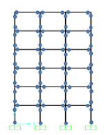 Figure 1: Bare frame with plastic hinges
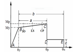 Figure 2: Moment –rotation relation of plastic hinge
2. Materials and methods
2.1. Modeling of concrete members
Frame members are idealized as elastic elements with a plastic hinge at each end. All material nonlinearities are concentrated in the plastic hinges. The properties of plastic hinges are defined as per FEMA 356 [13].
2.2. Modeling of infill wall
Lateral strength of infill wall is introduced in the analysis by modeling the infill wall by two diagonal struts. Diagonal strut carries only compression force. Properties of equivalent strut are calculated according to FEMA306 [14].
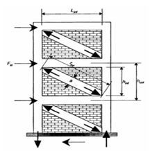 Figure 3: Diagonal strut for infill wall
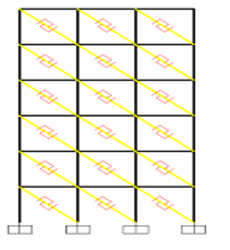 Figure 4: Link element idealization for compression strut
2.3. Parameters of diagonal strut
The width w of the equivalent strut is estimated according to Fema306. Nonlinearity is introduced in each diagonal strut by providing axial compression hinge.
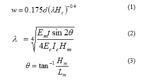 Where d is the strut diagonal length, Em is the masonry modulus, Ec is the concrete modulus, Hc is the column height, Hm and Lm are the height and the width of infill wall respectively. Ic is the moment of inertia of column, t is the infill thickness, q is the angle of inclination of diagonal strut.
3. Numerical investigations
3.1. Building description
To study the influence of infill panel on the seismic behavior of the building, a six stories reinforced concrete building is considered. The total plan dimensions are 9m x 9m. Total height of the building is 18m. The height of each storey is 3m. The columns are 30cmx30cm, 35cmx35cm and 45cmx45cm, the beams are 25cmx30cm for all floors, and the slab thickness is 13cm for all floors. The superimposed loads are 2.5KN/m2 and the live loads are 1.5KN/m2. Two models are considered, first model M1 is bare frame. The second model M2 is infill frame in which the lateral strength of infill is introduced by the concept of equivalent diagonal strut. The building is designed according to the RPS2000 and BAEL [15].
3.2. Properties of the diagonal strut
The frame properties are:
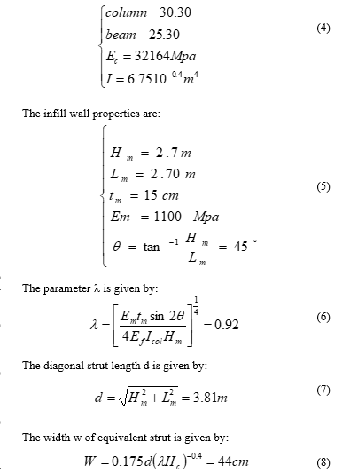
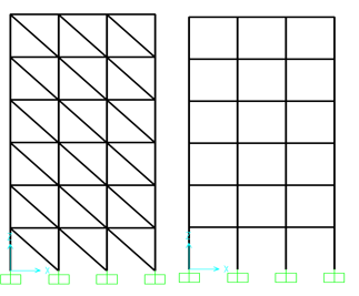 Figure 5: bare frame and infill frame models
| Table 1: Mechanical properties and parameters of the study |
| Storey | disp (cm) | disp (cm) | Ratio |
|
Bare frame (BF) |
Infill frame (IF) |
(BF-IF)/BF | |
| 6° storey | 5,02 | 2,14 | 57% |
| 5° storey | 4,48 | 1,94 | 56% |
| 4° storey | 3,54 | 1,61 | 54% |
| 3° storey | 2,52 | 1,21 | 52% |
| 2° storey | 1,36 | 0,72 | 47% |
| 1° storey | 0,47 | 0,28 | 40% |
| Table 2: Reinforcement of beams |
| Storey | Drift (%) | Drift (%) | RPS2000 |
| Bare frame | Infill frame | Drift limit (%) | |
| 6° storey | 0,18 | 0,06 | 0,5 |
| 5° storey | 0,31 | 0,11 | 0,5 |
| 4° storey | 0,34 | 0,13 | 0,5 |
| 3° storey | 0,38 | 0,16 | 0,5 |
| 2° storey | 0,29 | 0,14 | 0,5 |
| 1° storey | 0,15 | 0,09 | 0,5 |
Table 3: Reinforcement of columns
| Column | Section | Long- reinf | Stirrups |
| 1° Storey | 45×45 | 12f16 | f6 E=15cm |
| 2° Storey | 45×45 | 12f16 | f6 E=15cm |
| 3° Storey | 35×35 | 12f16 | f6 E=15cm |
| 4° Storey | 35×35 | 8f16 | f6 E=15cm |
| 5° Storey | 30×30 | 8f16 | f6 E=15cm |
| 6° Storey | 30×30 | 8f16 | f6 E=15cm |
4. Results and discussion
4.1. Lateral storey displacements
Maximum displacement at different stories is presented in the table 4 and 5. Figures, from 6 to 11 show the base shear versus storey drift. It can be seen that displacements decrease when lateral strength of masonry infill is considered in the model. There is a major reduction in the lateral storey displacements and storey drifts.
Table 4: Lateral storey displacements
|
Parameter
|
Value | Unit |
| Concrete grade | 25 | Mpa |
| Steel grade | 500 | Mpa |
| Seismic Zone | 3 | *** |
| Site Factor | 1.2 | *** |
| Behavior Factor | 2 | *** |
| Importance Factor | 1 | *** |
| Infill thickness | 15 | cm |
| Masonry strength | 2 | Mpa |
| Slab thickness | 13 | cm |
| Concrete modulus | 32164 | Mpa |
| Masonry modulus | 1100 | Mpa |
| Steel Modulus | 200000 | Mpa |
Table 5: Storey drift of bare and infill frames
| Beam | Section | Top- reinf |
Bottom- reinf
|
| 1° Storey | 25×30 | 4f16+4f12 | 4f16+4f12 |
| 2° Storey | 25×30 | 4f16+4f12 | 4f16+4f12 |
| 3° Storey | 25×30 | 4f16+4f12 | 4f16+4f12 |
| 4° Storey | 25×30 | 4f16+4f12 | 4f16+4f12 |
| 5° Storey | 25×30 | 4f16+4f12 | 4f16+4f12 |
| 6° Storey | 25×30 | 4f16+4f12 | 4f16+4f12 |
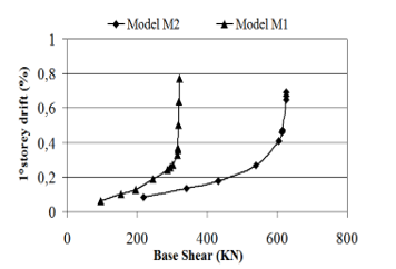 Figure 6: Base shear versus storey drift.1° storey
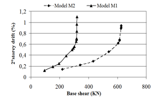 Figure 7: Base shear versus storey drift.2° storey
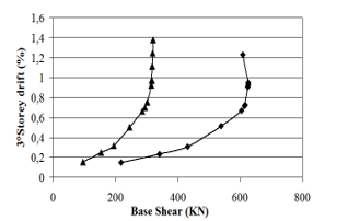 Figure 8: Base shear versus storey drift.3° storey
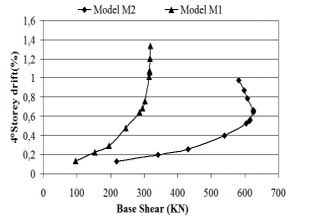 Figure 9: Base shear versus storey drift.4° storey
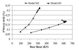 Figure 10: Base shear versus storey drift.5° storey
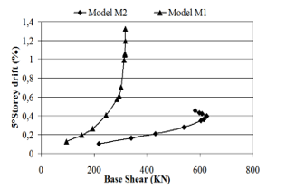 Figure 11: Base shear versus storey drift.6° storey
4.2. Natural periods of vibration
Table 6 shows vibration periods of bare frame and infill frame. It is found that introduction of masonry infill wall increases the lateral rigidity of bare frame; consequently fundamental period of vibration will be decreased. Bare frame idealization, under estimates the seismic design base shear.
| Table 6: Natural periods of vibration |
| Mode number | Infill frame | Bare frame |
| 6° storey | 0,251 | 0,419 |
| 5° storey | 0,083 | 0,136 |
| 4° storey | 0,049 | 0,078 |
| 3° storey | 0,036 | 0,054 |
| 2° storey | 0,029 | 0,042 |
| 1° storey | 0,027 | 0,036 |
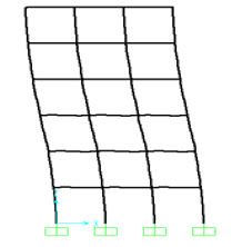 Figure 12: First mode of vibration (frequency=2.38Hz)
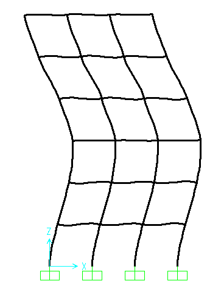 Figure 13: Second mode of vibration (frequency=7.35Hz)
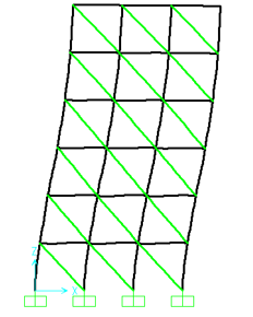 Figure 14: First mode of vibration (frequency=4Hz)
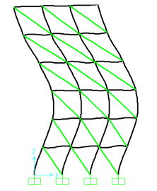 Figure 15: Second mode of vibration (frequency=12Hz)
4.3. Lateral strength and stiffness
Figure 16 shows capacity curves of bare and infill frames. It is found that lateral strength of infill frame is higher as compared to that of bare frame. The increasing in lateral stiffness reaches 2.5 times that of bare frame. Maximum strength of infill frame reaches 1.9 times that of bare frame. These numerical results obtained from this study agree with the experimental studies conducted by M.N Fardis et al [16], A.Hashemi et al [17] and A.Madan et al [18]. Experimantal results indicate that, inclusion of masonry infill increases both lateral stiffness and strength of bare frame.
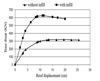 Figure 16: Pushover curves for bare and infill frame
4.4. Internal forces in the frame members
Figures 17, 18, 19 and 20 show the results of shear forces and bending moments obtained when lateral strength of infill is included or when it is ignored. It can be seen that there is an important change in the shear forces and bending moments in the frame members.
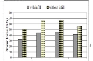 Figure 17: Change in the shear forces. Columns
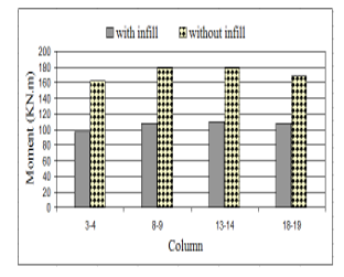 Figure 18: Change in the bending moments. Columns
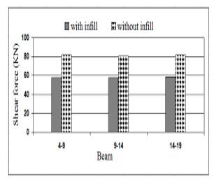 Figure 19: Change in the shear forces. Beams
5. Conclusion
In this study, the influence of infill walls on the seismic response of reinforced concrete buildings was investigated. The principal conclusions can be summarized as follows:
- Numerical simulations show that inclusion of masonry infill reduces significantly fundamental period. The maximum reduction reaches 40%. According to the response spectrum, when period decreases spectral acceleration increases, consequently the base shear design will be increased.
- Introduction of infill wall in the analysis reduces significantly seismic demands. The maximum reduction reaches 50% for lateral storey displacement and 66% for inter-storey drift.
- Inclusion of infill wall enhances lateral capacity of building. Initial stiffness reaches 2.5 times that of frame without infill, while maximum strength of infill frame reaches 1.9 times that of bare frame.
- Numerical investigations show also that there is a change in the internal forces in the frame members when lateral strength of infill walls was included. Bending moments of bare frame reached 1.60 times that of infill frame, while shear forces of bare frame reached 1.50 times that of infill frame. The infill frame resists lateral loads as a trussed frame then, flexural effects will decrease significantly.
Finally, the results of this study as presented in previous tables and figures, suggest that masonry infill walls change the response of the building when subjected to horizontal seismic forces. Seismic response of infill frame is too much different from that predicted by bare frame.
Conflict of Interest
The authors declare no conflict of interest.
- M.Mouzzoun and A.Cherrabi, “Seismic Behavior of reinforced concrete frame buildings with masonry infill” International Journal of GEOMATE, 17(63) 203–209, 2019.
- M.Mouzzoun, “Seismic behaviour of reinforced concrete frame buildings with masonry infill” PhD thesis, Mohammadia School of engineers, Morocco, 2015.
- S.V. Polyakov, “On the interaction between masonry filler walls and enclosing frame when loading in the plane of the wall” Earthquake Engineering Research Institute, San Francisco, 36-42, 1960.
- M. Holmes, “Combined Loading on lnfilled frames” Proceedings of the Institution of the Civil Engineers, 25, 31.1963.
- S. Stafford and C. Carter, “A method for analysis for infilled frames” Proceedings of Institution of Civil Engineers, No. 7218, 31-48, 1969.
- T.Paulay and M.N.Pristley, “Seismic design of reinforced concrete and masonry buildings” John Wiley, 1992.
- A.B. Mehrabi, P.B.Shing, M.P.Schuller and J.L.Noland, “Experimental Evaluation of Masonry-Infilled RC Frames” ASCE Journal of Structural Engineering, 122(3), 228-237, 1996.
- P. Negro and A. Colombo, “Irregularities induced by non structural masonry panels in framed buildings” Engineering Structures. 19(7), 576–585.1997.
- G. Al-Chaar, Evaluating strength and stiffness of unreinforced masonry structures. US Army Corps of Engineers. Construction Engineering Research Laboratories, 2002.
- P.G. Asteris. “Lateral stiffness of brick masonry infilled plane frames” Journal of Structural Engineering, 129(8), 1071–1079, 2003.
- RPS2000, Moroccan seismic code, Ministry of housing, 2000.
- CSI, Analysis Reference Manual for SAP2000, ETABS and SAFE, Computers and Structures, Inc. Berkeley, California, USA, 2005.
- FEMA356, Federal Emergency Management Agency, NEHRP recommended Provisions for Seismic Regulations for New Buildings and Other Structures, 2000.
- FEMA306, Evaluation of Earthquake Damaged Concrete and Masonry Wall Buildings, Basic Procedures Manual, Federal Emergency Management Agency, 1999.
- BAEL, Analysis and design of reinforced concrete buildings according to limit states method. European Committee for Standardization, 1991.
- M.N.Fardis, Experimental and numerical investigations on the seismic response of RC infilled frames and recommendations for code provisions, Report 6 of HCM-ECOEST Project, LNEC, Lisbon, 1997.
- A.Hashemi, K.M.Mosalam, K.M, “Shake-Table Experiment on Reinforced Concrete Structure Containing Masonry Infill Wall” Journal of Earthquake Engineering and Structural Dynamics. 14(35), 1827-1852, 2006.
- A. Madan, A.M. Reinhorn, J.B. Mander and R.E. Valles, “Modeling of masonry infill panels for structural analysis” ASCE Journal of Structural Engineering, 123(10), 1292-1297, 1997.