ROS Based Multimode Control of Wheeled Robot
 , Santosh Tantravahi, Hemanth Sai Surya Kumar Tammana, Nagasai Thokala, Hari Sudarshan Rahul Puram, Naveen Samudrala
Adv. Sci. Technol. Eng. Syst. J. 5(2), 688–696 (2020);
 DOI: 10.25046/aj050285
This research work mainly presents the design and development of a small-scaled wheeled robot, which can be controlled using multiple controlling interfaces using some new technological trends. Raspberry Pi 3 as the main controller, Python as the programming language integrated with the Robot Operating System (ROS) and Virtual Network Computing (VNC) for screen sharing are utilized in order to control the robot. Laptop Keys, Graphical User Interface (GUI) on PC, Virtual Network Computing on smart phones, Joystick connected to Laptop using python integrated with Robot Operating System, Voice commanding through an android app integrated with python and ROS and Internet of Things using a customized webpage with Node MCU as the controller are the dominant control interfaces. A Local Area Network is established in order to communicate with the micro-controllers wirelessly. The robot can be controlled with multiple interfaces by using its corresponding commands. The robot is made to survive in five different paths, controlled by all the six methods and the time for each response obtained was appraised and illustrated properly.
1. Introduction
Mobile robots are becoming increasingly popular across various sectors. They are used to assist with work processes and even accomplish tasks that are impossible, unreachable or dangerous for humans. Study of these robots had become an emerging field in the research world. Autonomous mobile robots (which can navigate themselves through an environment), guided robots (which travel through a pre-defined navigation route) and finally controllable robots (which travel according to the command received from a device). There are several types of mobile robots, which are controlled by different methods, depending on the need and operational conditions in the application environment. These robots are made resistant to harsh environments and are also available in several sizes too. Mobile robots had also introduced new trends in research.
The mobile robot, along with its control interfaces, is a simple device, made up of readily available materials. Raspberry Pi 3, which supports wireless communications, was selected as the single-board computer. PYTHON IDLE had been used as programming software to build keyboard and GUI control methods. The programs used for implementing the control methods were written in Python and were ROS integrated to implement joystick and voice control methods. This project also uses a Virtual Network Computing (VNC) viewer for smart phone purposes.
Six different methods were used to move the robot in desired direction: laptop PC, smart phone, GUI, joystick, voice command, IoT. The experimental results of three of these methods were already presented in [1] and in this research work, we added three more methods as extension of it. In [2] the voice command of eight languages is used for security system where as the app designed in this research work can take input command of many languages and can control the bot accordingly similar to that of [3]. Mobile control had been achieved using the VNC viewer by reducing its screen encoding time using the technique in [4]. IoT control method is similar to [5] but instead of an WIFI module and raspberry pi, we used NodeMcu which can both receive WIFI signal and control the robot. GUI and the laptop keys control were implemented by using raspberry pi as both microprocessor and microcontroller, where additionally Arduino in [6], and DSP in [7] were used for controlling the robot. This research work identifies the best method out of six selected modes of control. The best is determined based on the time difference between the time input is given and the robot finishes execution. This is to determine the speed efficiency of the robot, which is a major constraint in most of the situations. These tests conducted can be used to determine the speed with which these commands are transmitted and the processing speed of the controller board.
2. Motive
In recent times mobile robots have become more commonplace in various commercial and industrial applications. These robots are useful in reaching the places that are beyond human reach. Their uses are wide ranging. Primary motive behind the implementation of these mobile robots is to improve speed and efficiency. These robots when equipped with several types of sensors can improve functionality over wide range of applications. The robot can either move in an environment guided by the sensory inputs or be made to follow a specified trajectory. Usually, a terminal (computer user interface used to give input) is essential for controlling the bot. In situations where time is major constraint such as rescue robots, we need to send more commands to control the robot, our aim is to identify the best method for controlling such robots. Experimental results for three methods of control i.e. using Laptop, GUI, Mobile were tabulated before and are now extended by adding three more methods i.e. Joystick, Voice, IOT.
3. Related works
Condry and Nelson [8] presented a model that integrates control system gateways with smart IoT devices, using real-time challenge-response authentication for assured control operations. Agrawal et al. [9] offered a training method and algorithm, using a force-feedback joystick, with an “assist-as-needed” model for training vehicle drivers. [10] proposed a software structure, ASSOCIATES-ROS, for development of unresponsive, collaborative, multi-robot systems with copious software resources Shahzad [11] enlarged the Pymote structure to simulate packet-level performance. The extensions included radio propagation, energy consumption, and mobility. [12] discussed a new form of augmentative and alternative communication (AAC) device, for people with severe speech impairment. [13] proposed a method, to integrate the standard and throat microphone signals, for robust voice identification in clamorous environments. Kim’s team [14] proffered a novel approach to an auditory prototype, for robust speech identification in clamorous environments. [15] presented a book and straight forward hand gesture identification method, used in the mending of people who have flexibility issues, specifically stroke patients and victims with spinal cord injury (SCI).
The authors of [16] explained the simulation of mobile robot using three stage torque control. Author delineated [17] implementation and assessed viability and execution of an embedded application of the Convolutional Neural Network (CNN) algorithm on the Raspberry Pi 3 computer. The CNN-embedded algorithm classifies and quantifies dissimilarities among the frames. The convolutional neural network (CNN) algorithm which they used to detect faults in SHM works by taking an input image, assign importance to various aspects/objects in the image and be able to differentiate one from other and counts these variations as faults, which may not be true always. This algorithm may give a count more than the actual number of faults. [18] describes the execution and working principles of transportable, flimsy user-interfaces to approach implanted distant home-systems and home-networks. Authors in [19] proposed RemoteUI, which performs more efficiently compared to VNC in terms of bandwidth.
Mobile robot with single control interface is presented in [20]. Stabilization and tracking of a robot using a predictive controller with a time varying system is proposed in [21]. Isolated control interface, push-button control based movable robots in an untold domain using wireless sensor technology is presented in the research work [22]. [23] concentrates on avoiding singularity issues rather than the control interface, in an over-stimulated, artificial poly directional, wheeled movable robot [24] used the robot operating system platform for planning motion of poly directional wheeled movable robot instead of the control interface. Authors of [25] explained a novel method to control an orthotic arm using the EOG signals and also proposed a method by which a second person could control it. A low cost auto-navigated wheelchair is designed by authors of [26] using fixed path navigation with a Raspberry Pi, Arduino and rotation encoders. It works on the principle of Distance estimation.
4. Architecture of the system
The system architecture, as shown in Figure 1, is comprised of three major components: the command block, controller block, and the mobility block. The command block is constituted of six interface units: keyboard, smart phone, GUI, joystick, voice command, IoT. Keyboard is the first control interface. The VNC viewer installed on the smartphone is used as the second control method. The third robot mobility control method is the GUI, installed on any PC; next is a joystick connected to a computer or laptop. Voice commands, sent through a mobile app and the sixth method is through IoT (Internet of Things) using a Node MCU (Single board Microcontroller) with the commands coming from a smart phone. The Wi-Fi communication interface is used for transmitting commands and controlling the robot. Single-board computer i.e. Raspberry Pi 3, a Node MCU interfaced with Wi-Fi and motor drivers make the controller block. The mobility block is comprised of motor drivers, the wheels and the motors. Python is the language used to send commands from microcontroller to motor driver and in some of the methods, we used python programs integrated with ROS, to send commands.
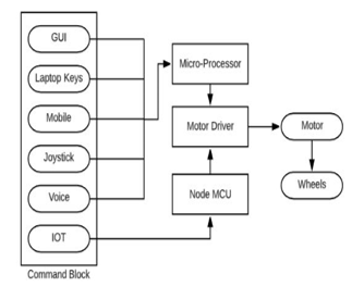 Figure 1: Robot Architecture
4.1. Command Block
Graphical User Interface (GUI) allows the control of robot through simple graphics. The GUI was developed using Python language, five different graphical buttons were created which helps in controlling the robot: up, down, left, right and stop. The robot’s front and back motion is controlled by the up and down buttons. The left turn, right turn and stop abilities of the robot is controlled with the help of left, right and stop button respectively.
VNC Viewer app is one of the means to control a wheeled bot, by a smart mobile phone through Wi-Fi communications. VNC viewer is used to control another computer by displaying its visual desktop on host computer connected over a network. Ensure that you have been given permission to remotely connect to the host computer. Once authentication is achieved, the VNC Viewer shows desktop of host computer in a new window. This is similar to the sharing desktop sharing of PC and controlling robot. VNC adapts itself automatically and dynamically to varying conditions, including differing screen contents and network bandwidths. VNC is also platform independent i.e. a Windows system can control a Linux system.
The keyboard of a laptop is used to send commands to the robot and control it to move in the desired direction. We used I, J, K, L and S keys in laptop to control the robot in various directions. Keys i, k, j, l and s are used to move the robot in forward, back, left, right directions and to stop the bot respectively.
A joystick is a input device which provides better control over the robot. It is easier to use by a human operator and steer a bot. Joystick often has one or more pushbuttons, called switches, whose positions can be monitored by the computer. The working of a joystick is based on the principle of conversion of physical movement into a digital signal, which when accepted by the device being controlled, produces the same results on the screen when connected to a computer.
4.2. Mobility Block
The mobility block is constituted of motor drivers, wheels and DC motors. Because of speed efficiency DC motors were better than stepper motors and also DC motors were low weight, small size, and minimum cost. Speed of a DC motor can be controlled by controlled by varying the supply voltage of the controller. In the context of this paper’s main objective, the robot should be as compact and lightweight as possible.
4.3. Controller Block
The controller block’s main components are a Raspberry Pi 3 computer and Node MCU. One of the six interfaces were used to send the commands. The controller block receives signal through WIFI, decodes these commands and generates control signal to the required modules to control the bot. The direction in which the robot moves is also being decided by the controller block depending on the received command.
5. Modelling the robot
The modeling of the robotic movements was carried out through three cases. The cases include – normal plane ground, robot going up an inclined plane and last, the robot going down the inclined plane. This kind of functional modeling offers an insight into the working of the robot in different terrains.
For all the equations presented here the following symbols are used and the meaning are as follows
N-Normal Force, Unit: Newton
m-Mass of robot, Unit: Kg
g-Acceleration due to gravity, Unit:m/s2
fs-Static force of friction,Unit:Newton
μs -Coefficient of static friction
id -Current drawn, Unit: Ampere
τ -Torque, Unit: Newton meter
KT -Torque constant for a DC motor, Unit: Newton meter/Amp
r-Radius of wheel
Figure 2: Robot on a flat surface
Considering the case of inclination angle zero i.e. plane ground, as shown in Figure 2,
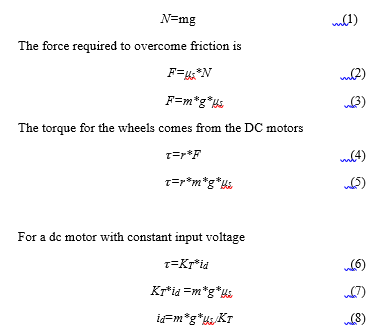 Here, id is the minimum current requirement for the bot.
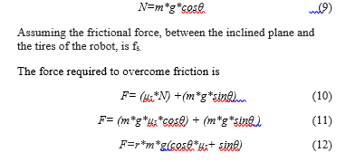
Similarly, considering the cases of inclination, where the angle of inclination is θ, as shown in Figure 3.
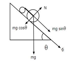 Figure 3: Robot moving up an inclined plane
 The torque for the wheels comes from the motors connected.
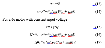 Here, id is the minimum current’
Similar to the above case, considering the inclined plane with an inclination angle θ and the robot moving down the plane as shown in Figure 4.
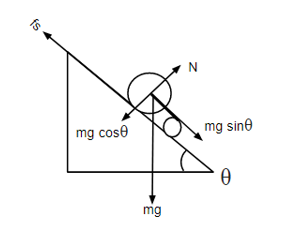 Figure 4: Robot moving down an inclined plane
Force required to overcome friction is
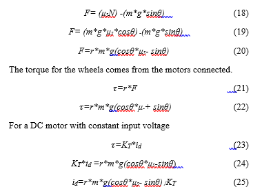 Here, id is the minimum current requirement.
6. Design and Implementation
Figure 5 shows about the mobile wheeled robot as implemented and tested by us in our lab. The hardware implementation comprises chassis of the robot, Raspberry Pi, circuitry for the control, motor drivers, motors, wheels, Node MCU and powering unit for controllers. The control methods include GUI, smartphone, keyboard, Joystick, Voice command and IoT commands.
6.1 Robot Chassis
The chassis of the robot is a cardboard made using a laser-cut of dimensions 0.2032 meter by 0.127 meter providing provision for integrating the motors, castor wheel, circuit, Raspberry Pi and a power unit. Two DC motors can be attached to the body. The load that is being carried by the robot, affects its speed. The robot circuitry and the chassis are shown in Figure 5.
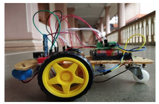 Figure 5: Mobile robot with its chassis and control circuitry
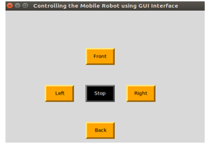 Figure 6: Python-based GUI on a laptop
6.2. Single Board Computer:
Raspberry Pi 3
Raspberry Pi 3, which is a single-board computer (SBC), is used as a micro-controller, with a 64-bit Quad core processor, GPU, ROM and Input/ Output pins on the System-on-Chip (SoC). It has 1.2 GHz single-core CPU, HDMI port, USB 2.0 port, GPIO pins and 1 GB RAM as its major parts. It is compatible with many Operating (OS) but “Raspbian” is the most commonly used OS.
Node MCU
NodeMCU is an open-source IoT platform.] It includes firmware that runs on the ESP8266 Wi-Fi SoC from Espressif Systems, and hardware which is based on the ESP-12 module. The board mainly consists of a built-in Wi-Fi-module, GPIO (General Purpose Input / Output pins) as its major components. To program the board, we use Arduino-IDE installed with ESP8266 library which acts as a programming tool for it. The NodeMCU used is shown in Figure 9.
Motor Driver:
Motor driver acts as an interface between Microcontroller and the motors. Motor driver is used to control speed and direction of motor rotation through the PWM signal that is coming from the microcontroller. The L293D is designed to provide bidirectional drive currents up to 600-] mA, at voltages over the range from 4.5 V to 36 V.
6.3. Control Methods
A keyboard with standard functionality either the PC or laptop keys is implemented to control the robot as one of the methods as shown in Figure 8. Mobile phones which supports Android platform installed with VNC can be used as an optional method for driving the robot. Developed in Python, the GUI for control of the bot is shown in Figure 6. The GUI developed is very easy to use and can be controlled remotely in any direction. Robot can be remotely operated through mobile phone using the VNC viewer mobile app, as shown in Figure 7. This can be done using a local area network (LAN) in which the VNC will be running in a server PC and we can control the robot remotely by using a mobile phone by the process of screen sharing. This process will be carried out until both the PC and the mobile phones are connected to the same network. By this way the robot will be controlled using the same GUI but using the mobile phone as the controller.
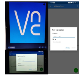 Figure 7: Mobile control using VNC
Raspberry Pi 3 is the major controller to drive the robot in stipulated environment. The motor driver acts as the mediator for supplying the power supply to the motors when a command arrives at the controller. Based on the commands given from any of the above-mentioned methods, the SBC intimates the motor driver and it regulates the speed according to the given command and passes to the wheels via motors.
 Figure 8: Keyboard based Control
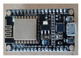 Figure 9: Node MCU
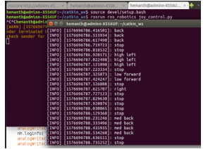 Figure 10: The commands received from the joystick
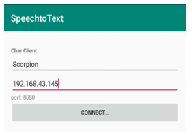 Figure 11: Speech App Interface for establishing a connection.
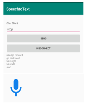 Figure 12: Sending voice commands using the app.
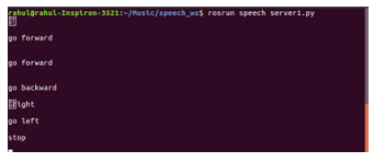 Figure 13: The data received from the VNC App.
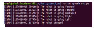 Figure 14: The received data from input device is being published to a Python file (where control is transferred to DC motors).
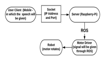 Figure 15: Flow chart of how data is being published to the Robot
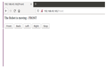 Figure 16: Web page created using html to control the robot.
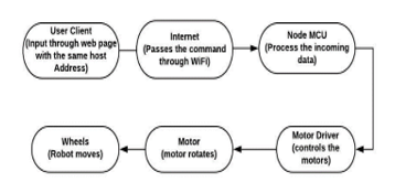 Figure 17: Flowchart for IoT control of mobile robot
The joystick used comprises of two 2 axis control sticks and 14 buttons. ROS integrated python file is used to transmit the commands given by the operator. The publisher node(program)establishes a connection between the user input data and the microprocessor. All these joystick commands from user are stored in a topic; these commands are then subscribed from the topic by the microprocessor (Raspberry-Pi 3) Based on the given input, Raspberry-pi 3 processes the data as shown in Figure 10, and send a signal to the motor driver, which facilitates the motor’s rotation in the desired direction.
Using this joystick, the bot is made to move in different directions: forward, backward, left, right, in different modes of speed – low, medium, high. The results obtained by operating the bot along several paths, in high-speed mode were noted and are tabulated.
There are different types of teleoperated robots, among which the major one is voice operated. There are several nodes which will act as publishers and subscribers to a topic. In this scenario, an app was created for controlling the robot as the input as the speech. The app interface is shown in Figure 11. This app basically works on socket programming. The socket programming is nothing but a server-client protocol. Here we are giving input from the app (using mobile) and it acts as a client. The hosted micro-controller (Raspberry -Pi) will be acting as a server. In this, the server and client should be connected to the same IP Address and Port. Port is a channel through which the data is publishing from a client to a server. The IP Address and the Port together are called a Socket. On the server-side, the data is integrated with the Robot Operating System (ROS). Through socket, the connection establishes between the server and the client. The input voice-command is fed from the app, as shown in Figure 12. The data being sent from the client is conveyed to the Raspberry-Pi 3 computer, as shown in Figure 13. From the SBC the data is delivered to a Python file, via a topic. As shown in Figure 14, the file acts as a subscriber node(program), in this case. From there subscriber gives commands to the motor driver, which actuates, the robot to move. Transmission of data, from a mobile app to the Raspberry-Pi 3 is explained using a flow diagram in Figure 15.
We implemented next method of control using concepts of IoT. Considering the scenario of IoT, Node MCU was used as the microcontroller for driving the robot. Node MCU was selected the microcontroller, since it has a built-in Wi-Fi module to control the robot, remotely. In actually controlling the mobile robot using a web page. The webpage is being built through html and integrated with Arduino – IDE. The web page will have some set of commands to drive the robot as shown in Figure 16. The Node MCU needs to be connected to a Wi-Fi network; from any web browser, the control of robot is accessible by typing the link IP Address. Then the web page created can be seen. The web page shows buttons which can control the robot just by clicking on any one of them. The web page will be acting as a client and the Node MCU will be acting as a server. Through -client-server protocol, the connection is established between the web page and the robot. when the button is clicked, user data gets published to the Node MCU; from there the robot’s actions are based on the specific input command. All these steps are shown, as a flowchart in Figure 17, the bot was made to move in different directions along different paths, by this method.
7. Experiments and Results
An even rectangular plane surface is selected for the experiment. The surface is with dimensions 2.04 meters in length and 1.2 meters in breadth. The test area closely resembles realistic situations, as opposed to non-realistic one and it is chosen in a closed room. All these test analyses (control of the robot in different paths) were carried out on the same plane and the path followed by the bot was delineated by a tape. For the better analysis of the robot we have created five different paths for the robot to transverse: rectangular path, straight-then turn right, straight-then turn left, navigate a U-turn and a straight path. In the above-mentioned paths, we conducted 5 trials, using each of the six modes: Keyboard, GUI, Smartphone, joystick, Voice command, IoT. 30 trials in total were conducted for each of these different paths. The recordings during these trials, were tabulated, to determine which is the fastest using the six modes.
Table 1: Time taken by bot to cover Straight Line Path in all the methods
|
Trial No. |
GUI (sec) | Mobile (sec) | Laptop keys
(sec) |
Joystick (sec) | Voice (sec) | IOT
(sec) |
| 1 | 5.1 | 5.1 | 5.0 | 5.2 | 6.1 | 5.2 |
| 2 | 5.3 | 5.2 | 5.2 | 5.4 | 6.2 | 5.2 |
| 3 | 5.3 | 5.1 | 5.0 | 5.5 | 6.1 | 5.2 |
| 4 | 5.4 | 5.2 | 5.3 | 5.3 | 6.2 | 5.3 |
| 5 | 5.1 | 5.4 | 5.5 | 5.4 | 6.4 | 5.5 |
| Mean(sec) | 5.3 | 5.2 | 5.1 | 5.3 | 6.2 | 5.2 |
| Mean(rps) | 1.9 | 2.0 | 2.0 | 1.9 | 1.7 | 2.0 |
Table 1 shows the transverse times for the robot using the straight-line path of 2 m in each of the six control modes. The analysis was recorded with the speed in revolutions per second (rps) being almost constant, but there is a negligible difference due to the latency of commands passed from the control end. Considering the results in which we have the lowest time taken method (using Laptop keys) and highest time taken method (using Voice), the analyzed difference between the timings is 1.07 (6.2 – 5.13). For this the number of commands required for controlling is one in all the above methods.
- Time taken by robot to cover Straight-right Path in all the methods
| Trial No. | GUI (sec) | Mobile (sec) | Laptop keys (sec) | Joystick (sec) | Voice (sec) | IOT
(sec) |
| 1 | 8.4 | 8.2 | 8.2 | 8.4 | 9.2 | 8.5 |
| 2 | 8.6 | 8.5 | 8.5 | 8.6 | 9.5 | 8.5 |
| 3 | 8.7 | 8.2 | 8.6 | 8.7 | 9.2 | 9.0 |
| 4 | 9.0 | 8.5 | 8.2 | 9.1 | 9.5 | 8.5 |
| 5 | 8.8 | 8.4 | 8.2 | 8.9 | 9.4 | 8.9 |
| Mean(sec) | 8.7 | 8.3 | 8.2 | 8.7 | 9.3 | 8.9 |
Recordings that were noted in Table 2 shows the straight-right trajectory duration of robot with the help of six control methods. The distance travelled is 2.04 m in a straight line (forward) and 1.2 m in the right direction. Considering the results of lowest time taken method (Laptop keys) and highest time taken method (Voice) with the help of recordings, the difference between the timings is 1.12 (9.36 – 8.24). For this the number of commands used for controlling is three in all the above methods.
Table 3: Time taken by the robot to cover Straight-Left Path in all the methods
| Trial No. | GUI (sec) | Mobile (sec) | Laptop keys (sec) | Joystick (sec) | Voice (sec) | IOT
(sec) |
| 1 | 9.4 | 8.6 | 9.0 | 9.4 | 10.2 | 9.5 |
| 2 | 9.5 | 8.7 | 8.9 | 9.5 | 10.4 | 9.3 |
| 3 | 9.5 | 8.2 | 9.1 | 9.5 | 10.3 | 9.4 |
| 4 | 9.0 | 8.7 | 9.2 | 9.0 | 10.2 | 9.5 |
| 5 | 9.5 | 8.5 | 9.0 | 9.5 | 10.1 | 9.4 |
| Mean(sec) | 9.3 | 8.5 | 9.0 | 9.3 | 10.2 | 9.4 |
In the scenario of the straight-left trajectory, the linear distance is 2 m and 1.2 m in a left direction and respective timings are recorded and they are shown in Table 3. In this scenario, the smartphone mode is the best in comparison to the other control modes by analysis. Considering the results of lowest time taken method (Mobile) and highest time taken method (Voice), the difference between the timings is 1.74 (10.24 – 8.5). Totally the number of commands used for controlling is three in all the methods.
Table 4: Time taken by the robot to cover ‘U’ turn Path in all the methods
| Trail no | GUI (sec) | Mobile (sec) | Laptop keys (sec) | Joystick(sec) | Voice (sec) | IOT (sec) |
| 1 | 13.4 | 14.8 | 13.3 | 13.2 | 15.8 | 13.2 |
| 2 | 13.3 | 14.9 | 13.3 | 13.4 | 15.9 | 13.3 |
| 3 | 13.0 | 14.9 | 13.3 | 13.3 | 15.9 | 13.4 |
| 4 | 13.4 | 14.4 | 13.4 | 13.1 | 15.4 | 13.4 |
| 5 | 13.3 | 14.6 | 13.4 | 13.2 | 15.6 | 14.0 |
| Mean(sec) | 13.2 | 14.7 | 13.3 | 13.3 | 15.7 | 13.4 |
Table 5: time taken by the robot to cover Rectangular Path in all the methods
| Trial No. | GUI (sec) | Mobile (sec) | Laptop keys (sec) | Joystick (sec) | Voice (sec) | IOT
(sec) |
| 1 | 17.2 | 17.6 | 16.4 | 17.2 | 18.6 | 18.1 |
| 2 | 17.6 | 17.5 | 16.2 | 17.6 | 18.5 | 17.2 |
| 3 | 17.2 | 17.3 | 16.5 | 17.2 | 18.3 | 17.5 |
| 4 | 17.4 | 17.7 | 16.4 | 17.4 | 18.7 | 17.4 |
| 5 | 17.6 | 17.6 | 16.3 | 17.6 | 18.6 | 17.,3 |
| Mean(sec) | 17.4 | 17.5 | 16.3 | 17.4 | 18.5 | 17.6 |
Table 4 gives the duration of the U-turn path covered by the robot. By the analysis, GUI mode provides the best timings compared to the other methods. The distance covered is 2 m linear up and down and breadth is 1.02 m. Considering the recordings, results of lowest time taken method (GUI) and highest time taken method (Voice), the difference between the timings is 2.76 (15.72 – 13.26). For this the number of commands used for controlling is five in all the above methods.
In the case of rectangular path, recordings of duration are shown in Table 5, With the analysis keyboard control shows better results in comparison to the other control modes. The results of lowest time taken method (Laptop keys) and highest time taken method (Voice) form the table V and the difference between the timings is 2.18 (18.54 – 16.36). For this the total number of commands used for controlling is seven in all the above methods.
8. Conclusion
From the results obtained from the experiments, we can observe that chosen 6 methods were equally efficient for simple paths. But, with the increase in complexity of the trajectory, the amount of control commands to be sent from user end also rises, which in turn increases the difference between time taken by the robot in different methods. So as this path complexity increases Laptop keys and Joystick control methods turned out to be efficient methods to control the robot in less time compared to other methods. Limitation of our study is that all the experiments are carried out using a network of 2.4GHz band, where as an 5GHz band network can be used for fast communication and less time period for the paths. In future this research work can be extended by implementing with a greater number of methods with higher band for large scale robotic applications where time is a major constraint.
Conflict of Interest
We, the authors of this paper hereby declare that we have no conflict of interest over the content presented in this paper.
Acknowledgment
We sincerely thank Electronics and Communication Engineering department and Humanitarian Technology (HuT) labs of Amrita Viswa Vidhyapeetham, Amritapuri Campus for the persistent help and support in conducting this research.
- R. K. Megalingam, S. Tantravahi, H. S. S. Kumar, N. Thokala and H. S. Rahul, “Multimode Control of Wheeled Bot Using Python and Virtual Network Computing,” 2018 4th International Conference on Computing Communication and Automation (ICCCA), Greater Noida, India, 2018, pp. 1-5. doi: 10.1109/CCAA.2018.8777597
- Luis Fernando D Haro, Ricardo Cordoba, Jose Ignacio Rojo Rivero, Jorge Diez de la Fuente, Diego Avendano Peces, Jose Maria Bermudo Mera,”Low-Cost Speaker and Language Recognition Systems Running on a Raspberry Pi”, IEEE Latin America Transactions Volume: 12 , Issue: 4 , June 2014
- Kateryna Zinchenko, Chien-Yu Wu, Kai-Tai Song,” A Study on Speech Recognition Control for a Surgical Robot”, IEEE Transactions on Industrial Informatics, Volume: 13, Issue: 2, April 2017
- Ha-Young Ko, Jae-Hyeok Lee, Jong-Ok Kim,” Implementation and evaluation of fast mobile VNC systems”, IEEE Transactions on Consumer Electronics, Volume: 58, Issue: 4, November 2012
- G. O. E. Abdalla and T. Veeramanikandasamy, “Implementation of spy robot for a surveillance system using Internet protocol of Raspberry Pi,” 2017 2nd IEEE International Conference on Recent Trends in Electronics, Information & Communication Technology (RTEICT), Bangalore, 2017, pp. 86-89.doi: 10.1109/RTEICT.2017.8256563
- K. Krinkin, E. Stotskaya and Y. Stotskiy, “Design and implementation Raspberry Pi-based omni-wheel mobile robot,” 2015 Artificial Intelligence and Natural Language and Information Extraction, Social Media and Web Search FRUCT Conference (AINL-ISMW FRUCT), St. Petersburg, 2015, pp. 39-45.doi: 10.1109/AINL-ISMW-FRUCT.2015.7382967
- J. D. Lee, Y. H. Wu, Y. J. Jhao, L. Y. Chen and H. I. Chen, “Development of mobile robot with vision inspection system and three-axis robot,” 2018 3rd International Conference on Control and Robotics Engineering (ICCRE), Nagoya, 2018, pp. 6-10. doi: 10.1109/ICCRE.2018.8376424
- Michael W. Condry, Catherine Blackadar Nelson, “Using Smart Edge IoT Devices for Safer, Rapid Response With Industry IoT Control Operations”, Proceedings of the IEEE (Volume: 104, Issue: 5, May 2016
- Sunil K. Agrawal, Xi Chen, Christina Ragonesi, James C. Galloway, “Training Toddlers Seated on Mobile Robots to Steer Using Force-Feedback Joystick”, IEEE Transactions on Haptics, Volume: 5, Issue: 4, Fourth Quarter 2012
- Zhongyuan Guo, Wenjing YANG, Minglong LI, Xiaodong YI, Zhongxuan CAI, Yanzhen WANG, “ALLIANCE-ROS: A Software Framework on ROS for Fault-Tolerant and Cooperative Mobile Robots”, Chinese Journal of Electronics, Volume: 27, Issue: 3, 5 2018
- Farrukh Shahzad, “Pymote 2.0: Development of an Interactive Python Framework for Wireless Network Simulations”, IEEE Internet of Things Journal, Volume: 3, Issue: 6, Dec. 2016
- Mark S. Hawley, Mark S. Hawley, Phil D. Green, Pam Enderby, Rebecca Palmer, Siddharth Sehgal, Peter O’Neill, “A Voice-Input Voice-Output Communication Aid for People With Severe Speech Impairment”, IEEE Transactions on Neural Systems and Rehabilitation Engineering, Volume: 21, Issue: 1, Jan. 2013
- M. Graciarena, H. Franco, K. Sonmez, H. Bratt, “Combining standard and throat microphones for robust speech recognition”, IEEE Signal Processing Letters, Volume: 10, Issue: 3, March 2003
- Doh-Suk Kim, Soo-Young Lee, R.M. Kil, “Auditory processing of speech signals for robust speech recognition in real-world noisy environments”, IEEE Transactions on Speech and Audio Processing, Volume: 7, Issue: 1, Jan 1999
- Rajesh Kannan Megalingam, Venkat Rangan, Sujin Krishnan, Athul Balan Edichery Alinkeezhil, “IR Sensor-Based Gesture Control Wheelchair for Stroke and SCI Patients”, IEEE Sensors Journal, Volume: 16, Issue: 17, Sept.1, 2016
- V. Gupta, N. Bendapudi, I. N. Kar and S. K. Saha, “Three-stage computed-torque controller for trajectory tracking in non-holonomic wheeled mobile robot,” 2018 IEEE 15th International Workshop on Advanced Motion Control (AMC), Tokyo, 2018, pp. 144-149. doi: 10.1109/AMC.2019.8371077
- A. Monteiro, M. de Oliveira, R. de Oliveira, T. da Silva, ”Embedded application of convolutional neural networks on Raspberry Pi for SHM”, Electronics Letters, Volume: 54, Issue: 11, 5 31 2018, 07 June 2018.
- P.M. Corcoran, F. Papal, A. Zoldi,” User interface technologies for home appliances and networks”, IEEE Transactions on Consumer Electronics, Volume: 44, Issue: 3, Aug 1998
- Daniel Thommes, Ansgar Gerlicher, Qi Wang, Christos Grecos, “RemoteUI: A high-performance remote user interface system for mobile consumer electronic devices”, IEEE Transactions on Consumer Electronics, Volume: 58, Issue: 3, August 2012
- L. Labakhua, I. Martins and M. Igor, “Control of a mobile robot with Swedish wheels,” 2017 IEEE International Conference on Power, Control, Signals and Instrumentation Engineering (ICPCSI), Chennai, 2017, pp. 267-272.doi: 10.1109/ICPCSI.2017.8392225
- M. M. Ma, S. Li and X. J. Liu, “Tracking control and stabilization of wheeled mobile robots by nonlinear model predictive control,” Proceedings of the 31st Chinese Control Conference, Hefei, 2012, pp. 4056-4061.
- G. Mester, “Wireless sensor-based control of mobile robots’ motion,” 2009 7th International Symposium on Intelligent Systems and Informatics, Subotica, 2009, pp. 81-84.
doi: 10.1109/SISY.2009.5291190 - C. P. Connette, C. Parlitz, M. Hagele and A. Verl, “Singularity avoidance for over-actuated, pseudo-omnidirectional, wheeled mobile robots,” 2009 IEEE International Conference on Robotics and Automation, Kobe, 2009, pp. 4124-4130. doi: 10.1109/ROBOT.2009.5152450
- J. Yin, G. Yang, F. Zhao and H. Qiu, “Motion planning implemented in ROS for Omni-directional Wheeled Mobile Robot,” 2015 IEEE International Conference on Information and Automation, Lijiang, 2015, pp. 2695-2700.
doi: 10.1109/ICInfA.2015.7279741 - Rajesh Kannan Megalingam ; Vineetha Nandakumar ; A Athira ; G S Gopika ; Anjali Krishna “Orthotic arm control using EOG signals and GUI” 2016 International Conference on Robotics and Automation for Humanitarian Applications (RAHA) Year: 2016 DOI: 10.1109/RAHA.2016.7931871
- Rajesh Kannan Megalingam; Jeeba M. Varghese ; “Study and analysis of embedded system based indoor navigation on multiple platforms”2016 International Conference on Communication and Signal Processing (ICCSP) Year: 2016DOI: 10.1109/ICCSP.2016.7754343