
On the Use of Triple Graph Grammars for Model Composition
Volume 5, Issue 2, Page No 653-664, 2020
Author’s Name: Hatime Bencharqui1,a), Younes Moubachir2, Adil Anwar1
View Affiliations
1Mohammed V University in Rabat. EMI, Siweb Team, Morocco
2Mohammed V University in Rabat. EMI, QSM Research Team, Morocco
a)Author to whom correspondence should be addressed. E-mail: bencharqui@gmail.com
Adv. Sci. Technol. Eng. Syst. J. 5(2), 653-664 (2020); ![]() DOI: 10.25046/aj050281
DOI: 10.25046/aj050281
Keywords: Model-driven development, Model composition, Formal approach, Triple graph grammars, AGG

Export Citations
In the software engineering research, several works focus on advantages of multi-modeling, which facilitate modeling a system by separating of concerns. The Model Driven Engineering approach relies on model to design software artefacts during the software development lifecycle. Handling such models involves describing some model management operators like ‘ composition ‘. That is an operation which consist to fuse a set of models into one (or more) incorporated model relating the application context. The present work, introduces a formal approach for UML-compliant model composition focused on three-actions: matching, checking and merging. Each composition action is represented by one or many graph transformations rules. The composition operator’s syntax is specified with triple graph grammars (TGGs) formalism.
Received: 30 October 2019, Accepted: 18 March 2020, Published Online: 14 April 2020
1. Introduction
In Model Driven Engineering (MDE), model composition is critical process, especially in modeling complex system with multi-modeling approach [1]-[4]. The primary goal is to distinguish issues related to the software system as model-views in accordance with certain particular concerns [5]: components, sub-systems, abstraction views, interactions. The goal is to facilitate analyzing and designing activities tasks during software development process. Nevertheless, this would make difficult the to integrate the different sub-models throughout subsequent phases.
To deal with this difficult operation, it’s very important to adopt appropriate approach, methods and techniques to maintain its consistency. The Model-Driven Engineering (MDE) approach is widely used that convert a process of integration to be operated automatically. In the model driven engineering approach these integration operations are assimilated to model transformations [6], [7]. However, this lacks formal foundations, and hence properties (e.g. commutative, associative) cannot be proven [8]. Such properties are useful to guarantee, that there is no influence of composition order in the operation of composition. we use the formal basis of graph grammars so that give a powerful background in the scope of model composition [9]. Some activities related to MDE process can also be applied in Graph theory [9]-[13]. In addition, using graph transformations theory to formalize model makes it possible to use benefits and richness of current tools like AGG [14], Fujaba [15] and Great [10].
To tackle the model composition issue, we propose a new method that uses graph transformation with Triple Graph Grammars (TGGs). TGGs is defined as a formalism to handle models that use transformation rules. we explain a composition operator that we had developed in our previous work [16] in response to different contextual purposes.
The use of TGGs provides several benefits concerning model composition: excellent comprehension, simplicity to express declarative composition rules and an effective approach with formal software tools. Crucial analysis can also be used to automatically identify all interactions and contradictions between the graph production rules. In addition, a formalism depicting the composition operation is presented.
The formalism is founded on two models’ relationships [8]. specifically, Models are subsequently considered to be graph-based artifacts, so we represent the relationships among models with two different equivalence categories. We will explore how composition operation can be accomplished by using relations between graphs.
Our work is built up as bellows. In section 2, a case study is presented to illustrate the different concepts of our composition approach. Section 3 exposes a formalism based on graph theory, in order to define the concepts of models and their relationships. In section 4, elucidates the suggested method by implementing triple graph grammars and explores some experimental information. the section 5 is devoted to related works. Section 6 sums up our contributions and outlines some upcoming work.
2. Motivating Example
2.1. Case study
This section is devoted to a short overview of the modeling approach, after that, a case study is presented illustrating our composition method, that functions as a driving example to illustrate the compositional approach.
The purpose is to fuse two UML models developed separately by two distinct designers. We present the merging scenario using a Library Management System (LMS). To simplify the presentation, our example will focus only on the following actors and activities:
- Librarian save the loans and save the return of loans. To manage these, the librarian must know the identity of the borrower;
- Head Librarian manage books and members (add, delete, change);
Those actors have multiple concerns, so this will affect the way in which the system can be designed. The goal of the requirements analysis step is to identify functional requirements of the system. In this step, a use case diagram is used. (Figure 1).
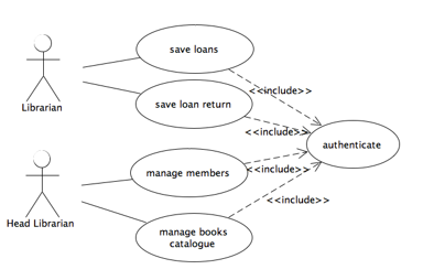 Figure 1: LMS snippet use case diagram.
 Figure 2: LMS snippet use case diagram.
Other models are used throughout the development process: class diagrams, state machines, etc. In this work, we will concentrate our studies on structural models.
In order to put into practice, the notion of point of view, Figure 2 and Figure 3 present class diagrams which are centered on each actor. Figure 2 illustrates an extract of the design model corresponding to the head librarian. We follow the same process to produce a design model (UML class diagram) for librarians and Library members.
2.2. Composition process
Our proposed method consists basically of three activities. First, we define between design models, some kind of relation of connection, the second activity consist of analyzing those established connections, and the last step consist of merging these models according to those correspondences. Composition process maintainability becomes easier due to the fact that the matching activity operation is sustainable than the merging one, which can be affected mainly by strategy modifications. Our proposed composition scheme will follow three different phases Figure 4: matchings step, checking step and merging step.
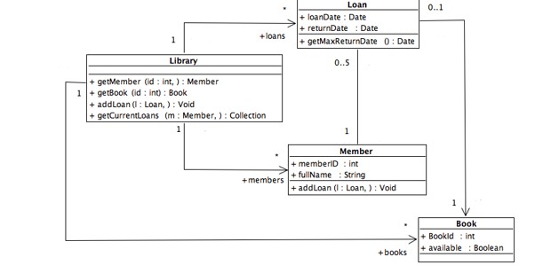 Figure 3: Snippet of Librarian actor design model
 Figure 4: Merging process of the design models.
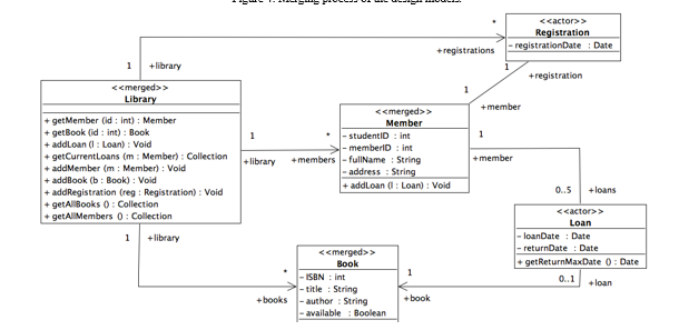 Figure 5: Class Diagram snippet of the LMS.
2.2.1. Matching step
Model Matching approaches can be decomposed into three categories according to the way the corresponding model elements are matched. (i) matching based on static identity, in this case we employs single and unîque identîfiers (ii) matching based on signature (iii ) matching based on similarity, within this technique, we compute the similarity value of an element feature, as an example, for UML class diagram, the similarity between two classes could be calculated by checking the similarities in their attributes or operations. The use of one technique instead of another depends on several factors such as the goal of the matching process and also the assumptions made about the application context, the nature of the models and their intention of use. For example, the static-based strategy won’t be interesting for model merging purposes, since we don’t look for elements which have the same value of the xml-id attribute but instead elements expressing the same principles, and designed to be similarly constructed. Additionally, Certain approaches focuses on similarity in graphs, for example, similarity flooding [17], To explore their matching degree, the authors use an algorithm to measure the resemblance of the adjacent nodes of elements. In addition, more the elements ‘ neighbors are different, more the similarity between those two elements decreases. It was regarded as the basis for further matching and merging set of rules like Ontology matching [18], and BPM merging [19].
 Figure 6:A graph depicting a UML class diagram as shown in figure 3.
| Librarian model’s Element | Correspondence Relationship | Head-librarian model’s Element |
|
Member Library Book Bookid memberId FullName |
Equality Equality Equality similarity similarity Aggregation |
Member Library Book ISBN SutdentID FirstName,LastName |
First of all, we identify in this step corresponding elements on the input models. This is can be achieved by creating correspondence links that relates these elements. This operation is called the model comparaison, since the computation of some type of relationships is only automated at this point (Equality, Similarity, Aggregation, Generalization). Equality relationship specifies equality as equivalent to two or more model elements, so the same concept is represented by tow designers in two different models. It might exist another type of Similarity that indicates that two or even more elements are semantically similar but not identical.
It is very important to express a specific correspondence relationship to differentiate operations which come with the same signature [20] (name, returned type, a set of parameters) with two different behaviors. In order to illustrate the result of the step, consider design’s models (Figure 2 and Figure 3) of the LMS example. These models can overlap in several ways: the classes Library, Book and Member of the Head Librarian model are likely to be the same as that in Librarian model. The BookId attribute defined on the Book class of the Librarian model is likely to be the same as the ISBN attribute of the head Librarian model. Similarly, the studentId and memberId attributes of the Member classes in models Figure 2 and Figure 3 respectively are likely to be the same as well. Assuming that all of these likely correspondences hold, the following is the set of correspondences relationships between the Head Librarian and Librarian classes models (Table 1).
2.2.2 Correspondences checking step
It’s commonly known that the related design models may present some consistencies because they have been constructed in a decentralized way; syntactic synonymy and certain differences within models are very probable. Applying some resolution strategies depend on how these cases are handled. For example, one can allow the matching of only a set of consistent models; others call for repair heuristics to correct inconsistencies before or during the matching operation. In our approach, we choose to repair conflicts after the matching step we tend to resolve conflicts, since checking the persisted elements wouldn’t be difficult than resolving conflict at the first input models.
 Figure 7: Type graph representing a simplified UML class diagrams metamodel with AGG tool .
Testing and validation of correspoence relation could be done at this step. Potential inconsistencies can be identified between input models. For example, the same concept represented in tow ore even more classes appear with different names. For example, the attributes memberId and studentId have been identified as similar in the earlier step. Here the designer intervenes in order to delete this correspondence because those concepts are semantically deferent. Certain kinds of correspondence relationships can be defined manually, such as generalization, aggregation dependency., In the LMS example, the Member’s name is represented in the Head Librarrian and the Librarian viewpoint models respectively by (firstName, lastName) and (fullName). Here, the designer intervenes in order to manually draw the aggregation correspondence between those elements.
2.2.3 Merging Step
At this point, we have applied tow techniques to merg models: merging technique and translating technique. We apply the merge technique on elements that are interconnected by the relations of equality. This is a default merging scenario, which is applied to relating elements among several models. Elements that have no corresponding one in the opposite model are by default translated into the merged model following the translation rules. In the case of 1 to many relationships, two merging strategies can be carried out, either representing the one element by the many or vice versa. In our example, we carried the second one (many-by-one).
The result of the composition process applied to the LMS example of Figure 2 and Figure 3 class diagrams is illustrated in Figure 5. We applied tow stereotypes (merged and actor) to the merged model classes, those two stereotypes swill help us to trace back the classes originated from one input model and which ones existed in both. For example, In the merged model, the library and member classes appear with the merged stereotype. Otherwise, the merge process labels classes with the stereotype actor (e.g., Registration class) that exist only in one source model. It is important to note that a tag attribute called actorName is added in order to trace the actors from which the class is originated.
3. Graph Transformation Theory
In the section above, we explain model composition operator is formalized over graph-based models, using graph transformation rules, also, how these are structed to create an overall operator referred as compose, then we introduce some properties of it as well as their demonstrations.
As reported by various studies, MOF-compliant models are basically graphing [21]. The whole formalization is based on the representation of the models as attributed graphs. The main idea is to use the graph transformation theory to specify the composition operator using a set of visual and formal graph transformation rules. Using this formalism for model composition offers many benefits, like : Simplicity for declaratively expressing composition rules, good understanding, and also suitable technique with formal analysis tools. In particular, critical pair analysis that can be used to automatically detect dependencies and conflicts between graph production rules.
In the following, we assume that UML models (class diagrams) are formally defined as oriented, labelled, typed graphs. These graphs are conforming and satisfy the constraints defined by another graph called type graph.
3.1. Basic definitions
We present in the following some basic definitions that are necessary to define our composition operator.
Definition 1. (graph-based model)
We assume that UML class diagrams are oriented labelled typed graphs. Then, each model is represented as a graph
Gr = (Ve; Ed; Sr; Tr; Lb; GGr) such that Ve and Ed represent respectively vertices and edges of graph (Ed Ì Ve * Ve ), function source Sr: Ed ® Ve and function target Tr: Ed ® Ve that relates edge to a vertex, and a multilabeling function Lb. The multi-labeling function Lb associates attributes to each element of the graph whether it is vertex or edge.
A graph morphism GGr GGr: Gr ® TGr which associates a type to every element in Gr. Vertices and node types are defined in the graph GGr called the type graph; this represents the UML language meta-model graph representations.
Figure 6 gives an example of an oriented labelled typed graph. For instance, the Association-End node representing the member Association-End has a labeled output edge and targets the member’s class node. This means that the aggregation Association named loan-member has as extremity the Class Member (Figure 3).
Corradini et al [22] proposed a powerful typing mechanism for graphs. This mechanism formalizes the conformance relationship between the models and the metamodel for the design language. Therefore, it is important to verify that it is conforms with a so-called TypeGraph. In the MDE method, the same principle is applied, where models conform to its meta-model [23]. The formal definition of type graphs is given below.
Definition 2. (Type Graph)
Let SVe and DEd be a set of vertices types and edges types, respectively. Let Gr = (Ve, Ed, Sr; Tr; Lb; GGr) be a graph. A type graph TGr is a labeled graph over S Ve and D Ed. Gr is typed over TG if there exists a graph morphism GG from G into TG (GG: Gr ® TGr). GGr associates graph elements of Gr to nodes of TGr. This implies that nodes and edges of Gr are constrained by nodes from TGr. GG : Ve * Ed ®S Ve È D Ed)
The type graph required to represent graphic model is illustrated in Figure 7. It should be generic enough to fit for a subset of any UML class-diagram. This type graph expresses a restriction on the graph-based models that are al- lowed: it specifies which types of edges may occur between certain types of nodes. the well formedness of graph-model is constrained by existence of a graph-morphism to its typegraph.
Definition 3. (Graph morphism)
Given two graph-based models Gr1 = (Ve1, Ed1, Sr1, Tr1, Lb1, GGr) and Gr2 = (Ve2, Ed2, Sr2, Tr2, Lb2, GGr) a graph morphism h from Gr1 to Gr2 is a pair of functions h = (hnode, hedge), with hnode: V1 ® Ve2 and hedge: Ed1 ® Ed2 Such that : “e1 Î Ed1 hnode (Sr1 (e1)) = Sr2 (hedge (e1)) and hnode (Tr1 (e1)) = Tr2 (hedge (e1))
Graph morphisms are viewed as a set of mappings between models, our aim is to prove that those mappings preserve the models structure, in other words, if an edge belonging to the first model is mapped to an edge belonging to the second, then, there exist a mapping of its source and target vertices too [24].
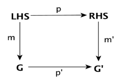 Figure 8: Graph transformation principle.
3.2. Graph transformation
Definition 4. (Graph production (rule)
Let LHS, RHS be two oriented, labelled and typed graphs. A graph production rule is a graph morphism pr: LHS à RHS
In case of a given graph Gr, we apply a graph production rules pr to perform transformation. This is made on three steps:
- To find a correspondence in graph Gr on the left side of LHS.
- To remove element of the concrete graph that is linked to LHS but not RHS.
- To glue the context graph previously created with vertices and edges of RHS that possesses no equivalent in LHS. The formal definition of graph production rule, which respect the single pushout approach with injective graph morphisms, has been proposed in [25].
Definition 5. (Graph transformation)
Following the definition given in [25] A graph transformation Gr Þt Gr‘ is defined as a pair t = (p,m) composing of a graph production pr : LHS®RHS and an injective graph morphism
mr: LHS® Gr. the use of category-theoretical construct, we may automate computing the morphisms m’: RHS’®Gr‘ and pr‘ : Gr®Gr‘ that make the diagram (p;m) commute. The Graph Gr ‘ is the outcome of the transformation applied by t to Gr.
The Figure 8 illustrates the principles of this definition.
4. Specifying Model Composition as Graph Transformations
We introduce our approach in this section, that applies triple graph grammars [11] and also the use of this approach on model composition.
Triple graph grammars offer a declarative and visual formalism for description of model transformation. The TGG formalism is appropriate with the QVTMOF norm [26] for dealing with the problem of model transformation. Furthermore, A variety of models-driven development process activities such as model-refactoring [9], model-synchronization[12], model-integration [13], etc can also be achieved using it.
4.1. Meta9modeling
The main reason behind the use of metamodels is the specification of composition rules in the formalism of TGGs, and also metamodels that are conform with the MOF. In the example presented in Figure 9, metamodels (source and target) are specified by UM/MOF. A third metamodel is used as composition metamodel. It is a model that permits the definition of all the links types for the graphical specifications of composition rules.
In Model-driven engineering area, a model is conform to its metamodel, the same principle may apply to the theory of graphs, which means that a given graph is conform to its type graph [11]. A type graph specifies both nodes type, edges type and constraints between them.
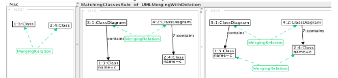 Figure 9: A example of a TGGs matching rule.
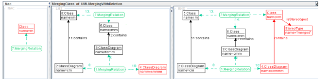 Figure 10: A example of a TGGs merging rule.
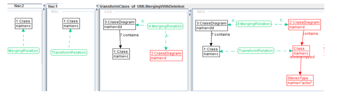 Figure 11:A example of a TGGs translation rule.
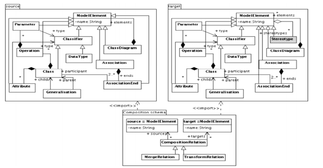 Figure 12:Composition metamodel.
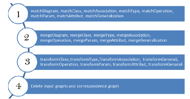 Figure 13:Transformation Rule layers.
The AGG defines metamodels as graph types. Typed attributed graphs are defined via node type inheritance, Nevertheless, node inheritance may not be allowed by the transformation rules and application requirements. this is the reason behind why we adopted a classical representation without node type inheritance. (Figure 9) illustrates packages via a subgraph. each type graph is shown in subgraphs. Related to the composition process, we may need to preserve and create a matching links between input model elements from the matching step. This will take us to use links for merging. by doing so, we create all of the matching links types needed to specialize the MergeRelation links type declaration. when link type is specialized, will determine a mapping link for every element type from source metamodels which would be used in the merging step producing elements in the merged model
4.2. specifying Composition Rules using TGGs
With TGGs formalism, the graph-rewriting rules will show the way in which the elements of a pair of graphs are linked by a third-graph, so-called correspondence graph. Especially, Every TGG’s rule consists of a rewriting pair of graphs and a third rewriting graph rules; those are used for checking and creating correspondence links between nodes of the two regarded graphs [13].
We recall that TGGs rules are considered as a set of declarative transformation rules of bidirectional graph transformations. In this section, we explain how, from these declaratives’ specifications, we derive some transformation rules for model composition purposes. These rules are into three categories: matching, merging and translation rules.
The matching rules are first executed over input models. In this particular step, the transformation is in-place, only correspondence relations are set up. The TGGs rules compute a valid correspondence between two existing graphs [27]. Each rule execution looks for a pattern corresponding to the rule’s LHS and not violating the NACs, if so, the RHS is produced and a correspondence pattern is arranged.
Figure 10 illustrates an example of a matching rule that creates a correspondence link between two equivalent classes. They are said equivalent if they hold the same name and belonging to two different models. Note that, a negative application condition is not shown, which eliminate many applications and creation correspondences links of this rule. As we have explained in the composition process section, some matching links could be created manually by the designer, so that they relate concept that are similar but differently modeled. Among the most important advantages of our method consist of separating the matching and merging operations. the main purpose of the merging transformation is treating the involved models and matching links as a single graph. The equivalent parts in the merged model are created by computing various matching links through merging rules. An example of a TGG rule that create a new class is given in Figure 11. In this rule, the newer class is linked to a merged model. The target production of the rule also specifies the generation of the merged stereotype according to our merging strategy.
Two classes that have the same label and but each of which belonging of a class diagram already merged (LHS). A merged class that has the same label as well as a merged stereotype is created, this will link the merged class to the merged class diagram. The default NACs guarantee the rules only apply once. AGG includes an editor for defining variables and attributes conditions. For instance, we used this feature to certify that the names of the two classes are identical in the Class Merging rule.
We have defined a set of transformation rules named “Translation rules”. Those rules apply a simple default behavior which consists of creating, a deep duplicate of the source model in the target model. We show in Figure 12 a translation rule illustration applied to a single class. It generates a Class and a stereotype element by initializing their corresponding attributes with the provided values. We remember as explained before, that the merged model must be earlier produced by the corresponding merge rule to which the new produced class will be attached to.
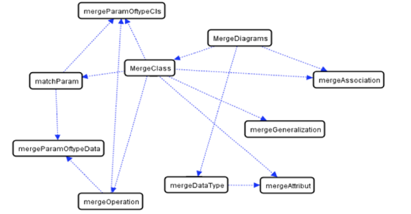 Figure 14:Sequential dependencies of merging rules.
5. Tool support
In order to validate the mentioned concepts, we carried out performed some practical experiments with AGG tool [14]. AGG tool is considered as one of the most known graph-based transformation tools implementing an algebraic approach for graph transformation. We have chosen this tool because it provides several advanced features of TGGs to specify complex transformations scenarios. As an example of advanced features, we can for example specify context constraints by using the specific attribute constraints. Also, we can specify a set of fillers with the concepts of Positive, Negative, and General Applications Conditions (PACs, NACs, and GACs). Within the GACs, one can apply combinations of former operators like AND, OR, FORALL over patterns. We can also perform some validations of graph transformation rules by applying advanced features by using consistency checking and critical pair analysis concepts. This is very useful to detect parallel conflicts and sequential dependencies [28]. Others features are applied to control flow of transformation rules, with rule sequences, layers and priority order [29].
5.1. Specifying rule layers
in this logic So we can consider the fact of as to havinge the same logical order as in the composition process, we may used rule layers to identifyspecify the transformations ow and decrease the complexity of the trans- formation application conditions. ThusSo, the matching rules appear first, the trans- formation rules come after the application of merging rules, and, obviously, the deletion rules come after the transformation process. Figure 13. shows composition rules sorted by rule layers.
5.2. Consistency checking with AGG
A consistency checking can be performed over the output model throughout consistency conditions (CC). A consistency condition describes graphically the graph properties as e.g. existence of a certain element or the independent of a certain rule. Also, a consistency condition is composed of a premise P and a conclusion C. Formally; a consistency condition is a total injective morphism
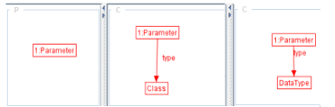 Figure 15: Dangling Parameter Type reference constraint.
 Figure 16: Check Class stereotypes constraint
In other words, for all the matches of the premise P in G, the conclusion C has to be fulfilled. We note that if we have multiple constraints then, G has to fulfill all these constraints. For instance, Figure 14 shows a consistency condition that specifies how to check that every parameter has necessarily a type. It is composed of one premise and two disjunctive conclusions (the satisfaction of one conclusion is enough). First, the premise is represented by a node of type parameter. Then, the associated conclusions assert that each node parameter has to be coupled (through- out the edge type) with either a node of type class or a node of type DataType.
Another example of a cc is depicted in Figure 15 which describes a consistency condition which specifies how to check that every class has essentially a stereotype with an attribute named actor or merged. The premise of the CC is the node Class, and the conclusion is a class connected to Stereotype with an attribute name actor or merged. When checking those CC over our output model and a window appears having the message the graph fulfills this atomic.
The transformation configuration of the AGG tool gives one the ability to stop after the execution of each layer and check manually the satisfiability of the constraints of interest. This, evaluates the correctness of the graph resulting so far, and prevents errors to be propagated.
As our transformation is composed of two major and separate steps (matching and merging), it is more convenient to assess the matching phase before starting the composition phase. Afterwards, comes the final checking phase to validate and ensure the correction of the output graph. Thereafter, a brief description of the constraints to be checked after each step:
5.2.1 Marching step
After this transformation step finishes, we check either the transformation behaved as expected or not by running the appropriate constraints over the graph resulted as yet. These constraints play on the one hand the role of a syntactic checker. And on the other hand, they say if the set of transformation rules reaches all the graphs nodes. For instance, checking if all the classes are reached can be translated by the following constraint. For each node Class this class should either be merged to another class or simply transcribed as it is. In other words, each node Class has to be linked to a node MergeRelation or TransformRelation. The same constraints can be extended to all the of the source type graph (Attribute, Association, Parameter).
5.2.2 Merging step
After that he merging step reaches its end another validation process take place. Using the appropriate model constraints, we check if the transformation consults and transforms every matching relation (MergeRelation or TransformRelation). For example, every Class matching relation of type MergeRelation have to be linked to a Class with the stereotypes name merged. We expand it for every matching relation linked to any node type.
5.2.3 Final checking
Despite the fact that the previous checking steps help vanishing ambiguities, how- ever, it is not satisfactory to tell that the results are correct. In some way, the constraints defined in this phase aid validating the syntactic properties of the out- put graph.
5.3. Sequential Dependencies between rules
This implementation activity is an important step to validate the syntactic correction of our composition process. During the definition of these constraints, we confronted a couple of difficulties, namely, the definition of complex constraints or negative ones. Other difficulties, adhere to those agged [9].
In fact, the graph of sequential dependencies between the trans-formation rules is computed by AGG, in order to retrieve the cross-dependency which in between (i.e is executing a rule depends on another execution). This graph is also intended to detect execution cycles. We talk about execution cycles when a sequence of rules gives a way to a rule previously triggered to be executed for the same matching. This prevents the transformation to turn in empty. We computed this graph for the merging step of our composition process. While analyzing the graph in Figure 16, we conclude that the rules mergeClass, mergeData, and mergeAssociation depend on the rule mergeDiagram, so this rule should be triggered first. Also, we come out with the conclusion that no cyclic executions are present in this transformation layer.
6. Related Works and Discussion
In the MDE approach, model composition is now one of the relevant activities in MDE approach. According to [30], On the one side, matching requires consistency, efficiency and simplified approach. On the other side, the merging step requires; conflict identification and resolution and consistency preservation. In the section that follows, we used graph grammar to transform these requirements to model composition in an ad-hoc manner.
Merging strategy: This technique could be divided into in-place techniques and out-targeted techniques. The first one consists of merging the input models into one global model named the host model along with their correspondence model. This strategy has many advantages such as simplicity, so a new model is not necessary to define the global view. Nevertheless, the input models are no longer available and to return and get them back is not guaranteed. The second strategy maintains the inputs unchanged and completely computes their union into a novel target model.
Conflicts management: Conflict can occur when the input models overlap. Many solutions require merging only consistent models, this operation requires a preliminary step to conflict resolution. Matching process automation: this activity could be performed automatically, semi-automatically or manually. In certain situations, the designer must make the final drawings of models matching when dealing with inconsistencies or when describing other relationships that are not evident (e.g. generalization or aggregation).
Change propagation: Models are updated and revised regularly. Therefore, some model views require the transformation at the beginning stage of design. Therefore, it is important to preserve traceability between input models in order to avoid the merged model being computed in case of any change in the source models.
In [13], The authors proposed an approach based on multigraph grammar principle to generalize TGG formalism and which besides presents a method to deal with data integration in heterogeneous distributed environment. On the one side, the integration mechanism relies on declarative rules to define communication relations between models. On the other side, they derive from those rules a set of operational rules which ensure accuracy among models and are responsible for the propagation of attribute changes from one element to the linked one. As with TGGs we can define constraints that are fairly simple, we propose the use of Layered graph grammars in our approach that permits to minimize the difficulty of constraints properties. The propagation mechanism as well as the integration, updates and changes were addressed using graph transformation rules. In [31], an EMF-based model management framework is suggested, including a collection of generic modules. The framework is founded on three notions: equivalent relations, inconsistency resolution and refreshment of the construct those steps are equivalent to our steps mentioned in our approach. To locate reused elements between two models, the Merge. operator employs the equivalence. relations specified in a metamodel. This method suppose consistency in the input models and consider only a simple relationship like a simple Association. this would facilitate automatization of matching operation.
Several approaches use matching step as primary step in model composition. UMLDiff [32] It introduces an automated structurall-differentiating. algorithm. UML-.aware. Based on the name and structural similarity of two models, it generates all modifications in the form of a tree structure. the use of heuristics makes it possible to establish such correspondence between elements by comparing both structural and lexical similarity between them.
A related work called GenericDiff [33], tak.es into a count all feature information of models, pa.ir-up feasibility predicates, and random walk tendency functions. This method compares two nodes to the recognizing off the Maximum Common Sub-graph (MCS) of two Typed Attributed Graphs by the use of an iterative process that propagates the distance value from nodes pair .to node pair based on graph structure and probability distributions. The major weakness of this method is to specify the appropriate threshold.
Finally, EMF Compare framework [34] is developed with a high level of extensibility to deliver good performance and efficiency. Some techniques such as instances, statistics and heuristics are used to achieve the matching phase. the authors use some metrics to weight this formula such as element’s name, their content, their types and the relations they have with other elements. In return a value ranging from zero to one, which will be balanced with additional factor’s scores the similarity between the source and target elements.
7. Conclusion
To sum up, our work was a mere investigation conducted to test the practicality of our approach using a graph transformation by means of AGG which appears to be the appropriate one to achieve and satisfy the following representation and visualization requirements: it is an investigation that goes along with the objective of our work, it is mainly about formalizing the model composition activity to produce an integrated view of all the individual views. We are totally concluded that tools like AGG accomplish the requirements presented earlier. To this end, we are going to examine a list of languages and tools specialized on graph transformation such as Tiger EMF[35 ] in order to choose the more appropriate to our method. we have formalized graphically the process by means of graph transformations. Composition rules are specified graphically using TGGS formalism. A set of attributed graphs allows both source and target model formal representation as well as correspondence model. The matching process is really aimed at adding a set of links to features of the source model. The correspondence graph is used to facilitate the automatization of the merging step and enable the correspondence graph to be incrementally refine. It also helps the traceability of the composition phase to be enhanced. The scope of this research could be broadened to various lines. our method was specified and proved in case of UML models context. however, it is entirely generic because majority of specification concerns graphs features. Therefore, it can be simply applied to any graph-based model composition. it is an important to automate the detection of possible concordances or conflicts between models towards implementing the proposed methodology to the big projects. So, we can use matching heuristics to compute similarities between elements of graphbased models.
- France R, Ray I, Georg G, Ghosh S. An aspect-oriented approach to design modeling. IEE Proceedings – Software, Special Issue on Early Aspects: Aspect-Oriented Requirements Engineering and Architecture Design 151,2004, 173.185.
- Sabetzadeh M, Easterbrook S.An Algebraic Framework for Merging Incomplete and Inconsistent Views.13th IEEE International Requirements Engineering Conference, (RE2005) pages 306-318, Washington, DC, USA, September 2005. IEEE Computer SocietyL.
- Finkelstein A, Kramer J, Goedicke M. Viewpoint Oriented Software Development. IC-SSEA. Toulouse, France,1990, pages 337-351.
- Clarke S.Extending Standard UML with Model Composition Semantics. Science of Computer Programming, 44 (2002). 71.100.
- Chechik M. A relationship-based approach to model management. In Model- Based Methodologies for Pervasive and Embedded Software, 2009. MOMPES09. ICSE Workshop on, pages 11. IEEE.
- [Kolovos D, Paige R, and Polack F. Merging models with the epsilon merging language (eml). Model Driven Engineering Languages and Systems, 2006,pages 215229.
- Anwar A, Ebersold S, Coulette B, Nassar M, and Kriouile A.A rule-driven approach for composing viewpoint-oriented models. Journal of Object Technology,2010, 9(2):89114.
- Anwar A, Dkaki T, Ebersold S, Coulette B, and Nassar M.A formal approach to model composition applied to vuml. In the 16th IEEE International Conference on Engineering of Complex Computer Systems (ICECCS)2011, on, pages 188197. IEEE Computer Society.
- Mens T, Van Eetvelde N, Demeyer S and Janssens D. Formalizing refactoring with graph transformations. Journal of Software Maintenance and Evolution: Research and Practice, 2005, 17(4):247276.
- Agrawal A, Karsai G, Neema S, Shi F and Vizhanyo A.The design of a language for model transformations. Software and Systems Modeling, 2006, 5(3):261288.
- Schrr A. Specification of graph translators with triple graph grammars. In Proceedings of the 20th International Workshop on Graph-Theoretic Concepts in Computer Science,1994, pages 151163. Springer-Verlag.
- Giese H and Wagner R. Incremental model synchronization with triple graph grammars. Model Driven Engineering Languages and Systems, pages 543557, 2006.
- Knigs A and Schrr A. MDI: A rule-based multi-document and tool integration approach. Software and Systems Modeling, 5(4): 349368, 2006.
- Ahmed A. et al., “Modeling and Simulation of Office Desk Illumination Using ZEMAX,” in 2019 International Conference on Electrical, Communication, and Computer Engineering (ICECCE), 2019, pp. 1–6.
- Niere J and Zu ndorf A. Using fujaba for the development of production control systems. Applications of Graph Transformations with Industrial Relevance, pages 301304, 2000.
- Anwar , A. Benallam , M. Nassar et B. Coulette. A Graphical Specification of Model Composition With Triple Graph Grammars . Lecture Notes in Computer Science (LNCS), volume 7706, p. 1 – 18. Springer, Heidelberg , 2013.
- Melnik S, Garcia-Molina H, and Rahm E. Similarity flooding: A versatile graph matching algorithm and its application to schema matching. In Data Engineering, 2002. Proceedings. 18th International Conference on, pages 117128. IEEE, 2002.
- Jean-Mary Y.R, Shironoshita E.P, and Kabuka M.R. Ontology matching with semantic verification. Web Semantics: Science, Services and Agents on the World Wide Web, 7(3):235251, 2009.
- La Rosa M, Dumas M, Uba R, and Dijkman R.M. Business process model merging: an approach to business process consolidation. ACM Transactions on Software Engineering and Methodology (TOSEM), 2012.
- France F, Fleurey F, Reddy R, Baudry B, and Ghosh S. Providing support for model composition in metamodels. In Enterprise Distributed Object Computing Conference, 2007. EDOC 2007. 11th IEEE International, pages 253253. IEEE, 2007.
- Mens T. On the Use of Graph Transformations for Model Refactoring. GTTSE 2006: 219-257.
- Corradini A, Montanari U, Rossi. Graph processes. Fundamental Informaticae, 26(34):241265, 1996.
- Bezivin J. Model driven engineering: Principles, scope, deployment and applicability. In Proceedings of 2005 Summer School on Generative and Transformation Techniques in Software Engineering, 2005.
- Marchand J, Combemale B, Baudry B, A Categorical Model of Model Merging and Weaving. In 4th International Workshop on Modelling in Software Engineering (MiSE 2012), in conjunction with ICSE 2012, IEEE, 2012.
- Ehrig H and Lwe M. Parallel and distributed derivations in the single-pushout approach. Theoretical Computer Science, 109:123143, 1993.
- OMG 2002. OMG/MOF Meta Object Facility (MOF) 1.4. Final Adopted Specification Document. formal/02-04-03.
- Greenyer J and Kindler E. Reconciling tggs with qvt. Model Driven Engineering Languages and Systems, LNCS pages 1630, Springer-Verlag 2007.
- Bottoni P, Taentzer G, and Schurr A. Efficient parsing of visual languages based on critical pair analysis and contextual layered graph transformation. In Visual Languages, 2000. Proceedings. 2000 IEEE International Symposium on, pages 59 60. IEEE, 2000.
- Ehrig H, Ehrig K, De Lara J, Taentzer G, Varro D, and Varro -Gyapay S. Termination criteria for model transformation. Fundamental Approaches to Software Engineering, pages 4963, 2005.
- Fortsch S and Westfechtel B. Differencing and merging of software diagrams. State of the Art and Challenges, 2007.
- Boronat A, Cars J.A , Ramos I, and Letelier P. Formal model merging applied to class diagram integration. Electronic Notes in Theoretical Computer Science, 166:526, 2007.
- Xing Z and Stroulia E. Umldiff: an algorithm for object-oriented design differencing. In Proceedings of the 20th IEEE/ACM international Conference on Automated software engineering, pages 5465. ACM, 2005
- Xing Z. Model comparison with genericdiff. In Proceedings of the IEEE/ACM international conference on Automated software engineering, pages 135138. ACM, 2010.
- Brun C and Pierantonio A. Model differences in the eclipse modelling framework. UPGRADE, The European Journal for the Informatics Professional, 2008
- TFS Group, Technische Universitt Berlin. EMF Tiger (2009). http://tfs.cs.tuberlin.de/emftrans