Hybrid Autogyro: Model and Longitudinal Control for Wind Gust Energy Conversion Using Autorotation

Adv. Sci. Technol. Eng. Syst. J. 5(2), 393–398 (2020);
 DOI: 10.25046/aj050251
In the new technologies for producing electricity from wind gusts, a new class of wind power converter has been proposed. The hybrid autogyro uses the principle of autorotation to generate lift. This paper proposes to take advantage of this rotation to also generate energy. There are systems that use flying wings or airplanes to reach winds that blow in layers of the atmosphere that are inaccessible to traditional wind turbines. Wind gusts are disturbances that significantly affect the behavior of this kind of aircraft. However wind gust is the source of energy and this wind speed increases with the aircraft’s altitude. This paper reviews the mathematical model of the hybrid autogyro aircraft and proposes a control algorithm to ensure that the vehicle remains horizontal in forward flight, in this way is possible to maximize the generated energy, this concept is tested in numerical simulations.
1. Introduction
The arrival of the 21st century brought a great advance in technology. Unmanned Aerial Vehicles (UAV’s) are now the object of interest by sectors of society that find more and more applications, for example to explorer areas which are difficult to access or imply high risk for humans [1]. UAV’s present great advances in design and control, due to the versatility of the applications [2, 3]. On the other hand, well-known techniques that use natural resources such as solar radiation, wind gusts or the water flow of rivers, could be improved by using UAV’s for inspection and maintenance work [4, 5]. Furthermore, wind generators, solar panels, hydroelectric dams among others, have high-impact environmental and economic costs. In addition, there are cases in which geographical and environmental areas have very specific characteristics [6]. In recent years, air vehicles have presented advances in design and control thanks to a large number of applications and scopes.One of the advances is to generate energy using wind gusts. In [7] the authors present a study of the technologies used to generate energy. The techniques used for wind gusts can be arranged in three main groups of generation [8]:
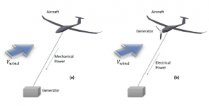
Figure 1: (a) Ground generation. (b) Generation on board.
On board case has the purpose of converting the wind gust to energy using electric generators like the Makani Company [9]. Ground generation case, the traction generated by the gust of wind on the aircraft which is attached to some mechanism on the ground. In [10]-[13] are presented different techniques to transform that traction force into energy. This technology is developed to obtain benefits from wind gusts once the aircraft is on the air. However take-off and landing of the aircraft are high risk maneuvers and are performed manually.
The first model of the autogyro was developed by Glauert and Wheatley in the early 30’s [14, 15], who introduced the concept of blade element impulse, a phenomenon responsible for the state of autorotation. Developed by the Spanish engineer Juan de la Cierva in 1923, the autogyro can be described as the antecedent of the modern helicopter. The principle of self-rotation consists of a free rotation wing for the elevation generated by the induced wind. This aircraft is powered by engine (equivalent in classic airplane). Thanks to self-rotation, landing and take-off are possible on a much shorter runway, even under specific wind conditions, short take-offs or jump start is possible. There is a great variety of aircrafts applied to the generation of energy and there are different techniques of flight for obtaining energy.
This paper proposes an autogiro with fuselage and a control surfaces as an airplane to generate pitching moment. The main difference is that it uses a free rotating wing which changes the angle of the lateral inclination to generate the roll moment of the aircraft, similar to the classic helicopter. The implementation of a fixed wing for the autogyro fuselage is presented in [16]-[19], the improvement in performance is shown by the authors.
The paper is organized as follows: Section 2 presents the autorotation in vertical flight and forward flight. Section 3 describes the mathematical model of the autogyro and its dynamics. Section 4 describes the longitudinal control law. Section 5 is devoted to the energy conversion. Final remarks are given in the conclusions in section 6.
2. Autorotation
2.1 Autorotation in vertical flight
Sometimes an auto start system (engine that drives the rotor) is used for the take-off at a very short distance, producing an almost vertical take-off. Similarly, the landing is done almost vertically and in slow-soft landing. The autogyro as others aircrafts obtains the lift from the wind upwards that crosses the disc formed by the rotation of its main rotor inverse to the helicopters. This wind gust generates aerodynamic forces along each propeller which allow the autorotation [20, 21].
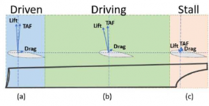
Figure 2: (a) Driven: A bearing force is generated orthogonal to the wind incidence, the total aerodynamic force is soft-opposite to the rotation. (b) Driving: A greater lift force is produced, the region farthest from the center hub is the one with the highest speed, the total aerodynamic force is positive to the rotation. (c) Stall: Mechanically it is where the axis of rotation and hub of the helices is located.
The Lift force, Drag force and the Total Aerodynamic Force or TAF are the forces with which it is possible to generalize its operation and that vary along the regions of each blade [22].
2.2 Autorotation in Forward flight
Landing and take-off are important stages in flight. The forward displacement generates aerodynamic forces that must be considered. The autorotation, takes advantage of the wind incidence. The autogyro must remain in forward flight to generate lift in the same way as an airplane.
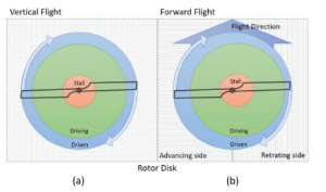
Figure 3: From a top view its possible to separate the rotation disk in left and right hemispheres, therefore the rotation is clockwise.
Figure 3 shows the aerodynamic forces due to the relative wind generated by the forward flight of the autogyro. The forward blade corresponds to the right hemisphere and the retreating blade corresponds left hemisphere. This relative movement of the forward blade presents an increase in its total aerodynamic force which is larger than the one produced by the retracting blade. This difference induces an angular momentum that could cause an overturn [23, 24]. A semi-cyclic plate is able to control the orientation by tilting the rotor disc using the roll moment [25].
3. Mathematical model
3.1 Equations of motion
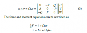
The six-degree of freedom rigid body dynamics equations will be developed in this section. The fundamental relations between forces and linear momentum rates and torques and angular momentum rates are
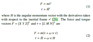
where the derivatives are taken with respect to the airframe
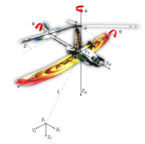
Figure 4: Autogyro Diagram
and v = [U V W]T is the relative velocities vector and ω = [P Q R]T is the rotation rates vector. Then, using the matrix cross product, the angular momentum is
where the individual state derivatives represents the forces and moments vectors, where it is established that in a hybrid autogyro the autorotating propeller is considered as a passive element, therefore the remaining dynamics may well be represented as that of a fixed-wing aircraft according to [27].
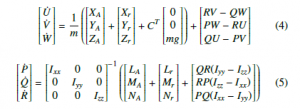
The weight vector g = [0 0 mg]T must be included with the direction cosine matrix or rotational matrix R, which rotates vectors from the body to the inertial frame. Euler angles describe the rotation with respect to the inertial frame. R matrix transform vectors from the body to the inertial frame and is defined as
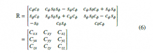
where cφ corresponds to cosφ, sφ corresponds to sinφ and the same for cθ,ψ and sθ,ψ [28]. The relation between Euler angles and the body angular velocities is the following
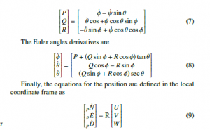
where pN, pE, pD represent the inertial frame positions (north, east, and down).
3.2 Wind model
The wind is introduced in the local frame, the body velocities [U V W] are converted to local velocities through the direction cosine matrix R. The wind velocities can be subtracted and the result converted back to the body frame to obtain the air relative velocity
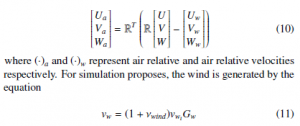
where νw is the constant wind intensity. A zero mean Gaussian noise turbulence term νwind with standard deviation σwind is added to 1 to perturb vwi this signal is then shaped by Gw to smooth the turbulence, where Gw is a first order low pass filter.
3.3 Forces and Moments
3.3.1 Rotor Forces and Moments
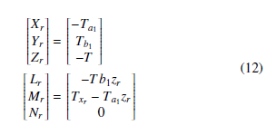
The forces and moments produced by the rotor considering the distance of the rotor hub from the vehicle center of gravity and if the flapping angles are assumed small, the equations can be simplified with sine and cosine approximations.
3.3.2 Aerodynamic Forces and Moments
The total aerodynamic forces and moments in the equations of motion are:
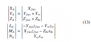
The approach to estimate these forces and moments is to assume that, similar to a helicopter, the lift force is generated by a rotating wing. However, an important aerodynamic difference is that the wind flow is upward through the rotor. Another difference is the absence of the moment produced by the helicopter motor. It is possible to find a more complete study in [29] where similar details to other aircrafts are considered.
4. Control Structure
Separate lateral and longitudinal controllers are constructed in decoupled modes and the two can be integrated with minimal risk of interference.
4.1 Longitudinal Control Design
The longitudinal dynamics is governed by a PID controller as an internal loop for attitude control. The controller includes the input pitch angle. The corresponding output is the deflection angles of the elevator δe. The longitudinal control law is as follows:
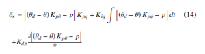
the desired angle is represented by θd. The Classical PID control strategy is used to control the attitude of the aircraft [26, 16] due to the fact that the attitude of the hybrid autogyro and the energy generation are independent processes. The PID Tuner app in Matlab was used for automatically tuning the gains of a controller to achieve a balance between performance and robustness.
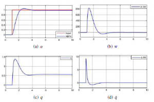
Figure 5: Step response. The response of the vehicle to the change of reference.
The inner loop PID controller for the longitudinal control corresponds to the pitch attitude control. The altitude control compares the pitch angle and desired pitch angle and uses it for pitch stabilization to reach the desired altitude (Figure 5). Then it commands the angle of the elevator to control the hybrid autogyro pitch and correct the angle of attack. The longitudinal control of the autogyro commands the flight up and down. In the presence of wind it is necessary to consider the angle of attack of the autogyro which must be regulated to keep the lift at aceptable level. Furthermore, the rotor can be tilted lateraly to make the autogiro turn [30]. To reduce the lifting force loss during the turning and maintain the altitude, this paper adopts the pitching elevator feedforward control method of the propeller (roll moment).
The response of the Hybrid Autogyro to a change of direction presents an effective control before the variation in the reference that may come from the change of direction in the altitude. Figure 6 presents the response of the angle of attack due to a disturbance or a change in altitude, the autogyro reaches its horizontal reference.
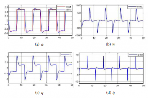
Figure 6: Square wave signal response.
5. Energy conversion
According to [31] the wind velocity variation can be observed in terms of the altitude. As shown in Figure 7, a terrain with obstacles like buildings or high trees produces a reduction in the wind velocity. In higher levels above ground we can find higher wind velocities but in fact also greater amount of opposite wind gust, which are considered as strong disturbances. The wind velocity variation versus the height above ground exhibits a parabolic shape depending on the ground roughness.
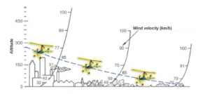
Figure 7: Altitude vs Wind speed for equilibrium flight 65km/h.(image taken from [31]).
If the speed of the autogyro (induced by the motor) is equal to the minimum wind speed required for the lift, then the autogyro performs a stationary or suspended flight without displacement. Actually, finding this balance in wind speed represents an ideal for energy conversion. The autogyro can remain in flight without using energy in the engine, which represents the highest energy consumption during the flight. Other avionics components (servomotors, sensors, autopilot, etc.), only used for the attitude control, represent a lower energy consumption, which means an increase in flight time [32]. The higher wind speed could represent a negative displacement to the advance of the autogyro, in other words, it would be necessary to anchor the autogyro as a kite.
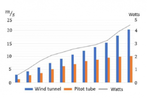
Figure 8: Wind speed vs energy in flight.
When the wind speed is above 65 km/h, the use of the main motor for producing lift may not be necessary. However the longitudinal control is crucial to improve the performance in the generation of energy (Figure 8).
![]()
6. Conclusions
The hybrid autogyro uses the principle of autorotation to generate lift and in this paper has proposed to take advantage of this rotation for energy generation by placing generators on the frame. However, the wind speed should be considerably higher to flight an autogyro than the wind required for fixed-wing vehicles. Therefore, the autorotation serves simultaneously to generate lift and to generate energy. It has been observed that it is important to consider the mathematical model and control algorithm of the autogyro to obtain a good behavior of the aircraft. Consequently and because wind gusts are also non-constant disturbances, the implementation of a control strategy that improves performance in altitude control is important for power generation. Nonetheless the wind is the source for power generation at high altitude.
A wide range of topics for the UAV’s that pursue the generation of energy, such as aerodynamics, avionics, control and energy is presented in this paper. Currently these areas are continually being developed promoting clean and renewable energy through specific UAV’s projects.
Conflict of Interest
The authors declare no conflict of interest.
Acknowledgment
This project was funded by UMI-LAFMIA 3175 CNRS, CINVESTAV and UTC, CNRS, UMR 7253 Heudiasyc. Finally to the National Council of Science and Technology (CONACYT) for the support.
- Rao, B., Gopi, A. G., & Maione, R. (2016). The societal impact of commercial drones. Technology in Society, 45, 83-90.
- Luppicini, R., & So, A. (2016). A technoethical review of commercial drone use in the context of governance, ethics, and privacy. Technology in Society, 46, 109-119.
- Finn, R. L., & Wright, D. (2016). Privacy, data protection and ethics for civil drone practice: A survey of industry, regulators and civil society organisations. Computer Law & Security Review, 32(4), 577-586.
- Rakha, T., & Gorodetsky, A. (2018). Review of Unmanned Aerial System (UAS) applications in the built environment: Towards automated building inspection procedures using drones. Automation in Construction, 93, 252-264.
- Jo, J., Jadidi, Z., & Stantic, B. (2017, October). A Drone-Based Building Inspection System Using Software-Agents. In International Symposium on Intelligent and Distributed Computing (pp. 115-121). Springer, Cham.
- Del Ro, P. (2010). Analysing the interactions between renewable energy promotion and energy efficiency support schemes: The impact of different instruments and design elements. Energy Policy, 38(9), 4978-4989.
- Cherubini A, Papini A, Vertechy R, Fontana M. (2015). Airborne Wind Energy Systems: A review of the technologies. Renewable and Sustainable Energy Reviews, 51, 1461-1476.
- Breukelman, P., Kruijff, M., Fujii, H. A., Maruyama, Y. (2014). A new wind-power generation method employed with high altitude wind. In International Conference and Exhibition, Grand Renewable Energy, Tokyo July.
- https://makanipower.com
- Ahmed M, Hably A, Bacha S. (2013). Kite generator system modeling and grid integration. IEEE Transactions on Sustainable Energy, 4(4), 968-976.
- White FM, Wolf DF (1968). A theory of three-dimensional parachute dynamic stability. Journal of aircraft, 5(1), 86-92.
- Argatov I, Rautakorpi P, Silvennoinen R. (2009). Estimation of the mechanical energy output of the kite wind generator. Renewable Energy, 34(6), 1525-1532.
- Canale M, Fagiano L, Milanese M. (2009). KiteGen: A revolution in wind energy generation. Energy, 34(3), 355-361.
- Wheatley JB. (1935). An Aerodynamic analysis of the autogiro rotor with a comparison between calculated and experimental results.
- Glauert H. (1926). A general theory of the autogyro (Vol. 1111). HM Stationery Office.
- Song, Z., Cai, Z., Li, K., Zhao, J., Liu, N. (2017, June). Model and Attitude Control of a Miniature Hybrid Autogyro. In Chinese Intelligent Automation Conference (pp. 751-760). Springer, Singapore.
- Liu, N., Cai, Z., Ma, Y., Wang, Y. (2017). Control and Flight Testing of a Miniature Compound Autogyro. In AIAA Atmospheric Flight Mechanics Conference (p. 3891).
- Hou, J., Cai, Z., Zhao, J., Wang, Y., Liu, N., Song, Z. (2017, December). Fuzzy and PSO-based PID controller for a hybrid autogyro attitude control. In Control Conference (ASCC), 2017 11th Asian (pp. 2160-2165). IEEE.
- Mackertich S, Das T. (2016, July). A quantitative energy and systems analysis framework for airborne wind energy conversion using autorotation. In American Control Conference (ACC), 2016 (pp. 4996-5001). IEEE.
- Duda, H., Pruter, I. (2012). Flight performance of lightweight gyroplanes. In 28th International Congress of the Aeronautical Sciences, Brisbane, Australia.
- Handbook, F. A. A. (2000). 8083-21. Rotorcraft Flying Handbook.
- Lin, Q., Cai, Z., Wang, Y. (2014, August). Design, model and attitude control of a model-scaled gyroplane. In Guidance, Navigation and Control Conference (CGNCC), 2014 IEEE Chinese (pp. 1282-1287). IEEE.
- Wheatley, J. B. (1934). The aerodynamic analysis of the gyroplane rotating-wing system.
- Lopez, C. A., Wells, V. L. (2004). Dynamics and stability of an autorotating rotor/wing unmanned aircraft. Journal of guidance, control and dynamics, 27(2), 258-270.
- Houston, S. S. (1998). Identification of autogyro longitudinal stability and control characteristics. Journal of Guidance, Control, and Dynamics, 21(3), 391-399.
- Deyst, J. J., & George, S. (2005). Simulation and control design of a gliding autogyro for precision airdrop (Doctoral dissertation, Massachusetts Institute of Technology).
- Arnold, U. Investigation of gyroplane flight mechanics (in German). Master Theses, Institute of Flight Systems, Braunschweig, 1988.
- Lozano, R. (Ed.). (2013). Unmanned aerial vehicles: Embedded control. John Wiley and Sons.
- D. H. Lorenz Meier and M. Pollefeys, px4: A node-based multithreaded open source robotics framework for deeply embedded platforms, International Conference on Robotics and Automation (ICRA), 2015.
- Breukelman, P., Kruijff, M., Fujii, H. A., Maruyama, Y. (2014). A new wind-power generation method employed with high altitude wind. In International Conference and Exhibition, Grand Renewable Energy, Tokyo July.
- Hartmann, D. L. (2015). Global physical climatology (Vol. 103). Newnes.
- Flores, J., Salazar, S., & Lozano, R. (2019, June). Hybrid autogyro: Airborne wind gust energy conversion using autorrotation. In 2019 International Conference on Unmanned Aircraft Systems (ICUAS) (pp. 1255-1260). IEEE.
No related articles were found.