
In-Plane Shear Behavior of Unreinforced Masonry Walls Strengthened with Fiber Reinforced Polymer Composites
Volume 5, Issue 2, Page No 360-367, 2020
Author’s Name: Sanaa El Malyh1,a), Azzeddine Bouyahyaoui1, Toufik Cherradi1, Ancuta Rotaru2, Petru Mihai3
View Affiliations
1Department of Civil Engineering, Mohammadia School of Engineer, Mohammed V University of Rabat, Morocco.
2Department of Transportation Infrastructure and Foundations, Gheorge Asachi Technical University of Iasi, Faculty of Civil Engineering and Building Services, Romania.
3Department of Concrete Structures, Building Materials, Technology and Management, Gheorge Asachi Technical University of Iasi, Faculty of Civil Engineering and Building Services, Romania.
a)Author to whom correspondence should be addressed. E-mail: selmalyh@gmail.com
Adv. Sci. Technol. Eng. Syst. J. 5(2), 360-367 (2020); ![]() DOI: 10.25046/aj050247
DOI: 10.25046/aj050247
Keywords: Composite materials, In plane, Masonry Wall, Strengthening, Fiber Reinforced Polymer, CFRP, Energy dissipation

Export Citations
Unreinforced masonry (URM) wall is one of the oldest types of walls used around the world. During earthquakes, URM walls present a real danger to life safety due to their behavior characterized by a brittle failure caused by their feeble shear resistance to in-plane loads, which make their strengthening necessary. Numerous studies had been used fiber reinforced polymer (FRP) as strengthening systems to upgrade the seismic behavior of masonry walls. In this study, the effectiveness of using carbon fiber reinforced polymer (CFRP) to increase the energy dissipation and the load carrying capacity of URM walls subjected to in-plane loading is experimentally investigated. Tests were carried on five walls subjected to diagonal compression loadings, one wall was considered as a reference and the other were retrofitted by different configurations of unidirectional CFRP wraps. Despite the advantages associated with the use of such systems, it remains expensive to use, therefore in this study, different ratio and configurations of CFRP wraps were used to reinforce masonry walls to enhance their resistance with less costs. The parameters under investigation are the dimensions, the number and the orientation of CFRP layers. It was concluded that the CFRP enhance the shear resistance and the deformability of URM walls. Results show The CFRP wraps had a significant influence on the URM wall behavior. Important amelioration of deformations and ultimate shear strength were observed when the specimen reaches its peak load, it was determined that the use of CFRP wrap even in smaller ratios increased ductility, the load-bearing capacity and the in-plane shear strength capacity of the masonry walls. The compressive strength of the strengthened walls had experimentally observed to be 147.31% to 319.35% higher than URM wall. The CFRP wraps presents an important solution for the improvement of the in-plane behavior of masonry walls.
Received: 21 February 2020, Accepted: 19 March 2020, Published Online: 26 March 2020
1. Introduction
After moderate or severe earthquakes, several damages occurred in structures and the most important ones were located in URM walls, which have shown less resistance to in-plane loadings. The fact that masonry walls were not covered in the design stage and in analyzes had led to important damages. Moreover, the seismic codes do not take into consideration the nonlinear response of these elements. Their failure due to either wind or earthquake is susceptible to be brittle and unexpected.
The evaluation of the buildings in Basel revealed that 45 to 80% of the existing URM buildings would experience damage grade 4 or 5, which correspond to very heavy damage and destruction [1], [2]. The fact that URM Walls are vulnerable to earthquakes makes their strengthening necessary. Recently different techniques had been developed to improve the seismic performance of existing or new URM structures, like the reinforcement by using fiber-reinforced polymer (FRP), which has an important displacement, elastic deformations, and effective in nonlinear domain. In addition, FRP is a cheap material, assure structure safety, can provide a high level of strength, and easy to deploy because most of them are characterized by a small weight and easy to apply to structures.
In literature, diverse strengthening systems were used by researchers the common ones are glass FRP, aramid FRP and carbon FRP, which were experimentally investigated to test their efficiency to upgrade the resistance of the walls by applying seismic loading either on the out plane or on in-plane directions.
Even if the FRPs have many advantages, but it has many limitations such as it cannot be applied to humid surfaces, no vapor permeability due to the presence of resin, however, they replace resin by a cementations matrix as an alternative of external retrofitting technique [3]-[5]. In addition, it could influence the architecture, and presents additional charges [6].
Experimental results of clay brick walls externally strengthened with glass FRP and aramid FRP laminates subjected to out-of-plane loads showed a significant increase in the flexural capacity [7]. Several researches have shown that the strength of masonry panels externally strengthened with FRP and subjected to diagonal compression loadings enhanced up to 15 and 70% [8].
The in-plane shear of URM walls retrofitted with composite materials were inspected within experimental or numerical studies. Results demonstrated that the use of retrofitting systems increases significantly the in-plane shear capacity of URM walls [9]-[11]. Even if the retrofit systems have an important effect on the ultimate strength of the wall; however, the FRP did not reach its ultimate strength at failure [12]-[17]. Stratford et al. [18] Investigated masonry walls reinforced by GFRP sheets, no remarkable amelioration in ductility was remarked, however the shear capacity increased by 65%. Reinforcement with FRP can be partial by using strips or total by applying the reinforcement to the entire surface of the walls [19].
Different configurations of reinforcement with CFRP plates using the NSM technique (horizontal reinforcement on one side, horizontal reinforcement on two sides and horizontal-vertical reinforcement on two sides of the wall) were used by [20] to repair the damaged masonry walls. Results show that the walls with the horizontal and the vertical reinforcement had the highest energy dissipation, resistance and deformation capacity. For Gharib et al. [21], the ductility and strength of the wall increased when using the vertical reinforcement bars. In addition, in the case of reinforcement by two horizontal layers, the resistance did not increase when it compared to walls reinforced with a single layer. Increasing the number of shear reinforcement layers is more effective when the fibers have angles of 0-90 °.
2. Objectives of Research
The main objective of this paper is to determine adequate retrofitting systems with the highest efficiency, which may enhance the stability of structures with less amount of FRP, to minimize costs with less intervention to maintain the same aspect of the original architecture of different type of structures. In this study, diverse configurations of strengthening system applied to four URM walls were tested under compression loading. Analyses of the experimental results are performed and a comparison between the five specimens was carried out to analyze the effect of CFRP wrap ratios on the energy dissipation, strength, stiffness and other mechanical characteristics of URM walls.
3. Experimental Program
An experimental program was pursued to investigate the in-plane behavior of the standardized specimens following ASTM E-519 [22], which provides a standard test method for testing masonry walls under diagonal compression loads to determine diagonal tension strength. The test consists of testing panels of 1200*1200mm fixed at the ends of their diagonal by two steel shoes, the diagonal compression forces were applied via the steel shoe located at the top corner.
All the masonry walls had the same dimension, and they were strengthened by different configurations of unidirectional CFRP wrap. The variables considered in this study were the ratio, number of layers and their dispositions. The principal aim of these tests is to investigate the influence of the orientation and the ratios of the reinforcement on the behavior of masonry walls.
3.1. Materials Characterization
The specimens were constructed by using clay bricks with dimension of 240*115*63mm, two types of mortar were applied one for linking bricks and the other was used on the wall faces. The unidirectional CFRP wrap used to reinforce URM walls via the interface of resin. The mechanical characteristics of aforementioned materials are illustrated in the table 1, table 2 and table 3.
Table 1: Characteristics of fibers according to ISO 10618 [23]
| Type of material | Fibers density | Thickness of CFRP wrap | Tensile strength (N/mm²) | Tensile modulus of elasticity (N/mm²) | Elongation at rupture |
| CFRP | 1.82 g/cm3 | 0.129 mm | >4000 | 230000 | 1.7 % |
Table 2: Characteristics of fibers according to EN 2561 [24]
| Type of material | Tensile strength (N/mm²) | Modulus of Elasticity in Tension (KN/mm²) | Nominal thickness (mm) | |||
| Laminate | Average | characteristics | Average | Characteristics | 0.129 | |
| 3500 | 3200 | 225 | 220 | |||
Table 3: Details about different materials
| Material types | Dimensions (mm) | Type of test | Standard used | Compressive strength (N/mm²) |
| Mortar ( Apply on bed and head of joints) | 40*40*160 | Flexural and compression strength | EN 1015–11 [25] | 4.47 |
| 50*50*50 | Compression strength | ASTM C109/C109M [26] | 3.31 | |
| Mortar (Apply on wall surface) | 40*40*160 | Flexural and Compression strength | EN 1015–11[25] | 27.84 |
| 50*50*50 | Compression strength | ASTM C109/C109M [26] | 13.85 | |
| Clay bricks | 240*115*63 | Compression strength | ASTM C-67-05 [27] | 11.28 |
| Masonry prism (3 bricks) of brick linked by mortar) | 240*200*63 | Compressive test | ASTM C1314 [28] | 10.83 |
| Masonry prism (2 units of brick linked by mortar) | 240*130*63 | Bond strength of mortar-masonry | ASTM C952 [29] | 17.43 |
3.2. Specimens Preparations
The preparation of the specimens passed through several stages; initially walls with dimension of 1200*1200*115mm were constructed by using clay brick units with dimension of 240*115*63 mm connected by 10mm mortar joints. The URM walls were cured for 28 days. The process of the application of CFRP wrap started with cleaning the both sides of the specimens from dust with a high pressure of air, and each face was wet.
The next step consists of applying a thin layer of primer followed by a layer of mortar, which were also cured for 28 days. Then to fix CFRP wrap two layers of epoxy-resin are applied one is used directly on the wall faces and the other is used after positioning different configurations of CFRP wrap. All the specimens were retrofitted on both faces. After seven days, the walls were tested under diagonal compression loading.
The abbreviations used for the specimens are URM-WR, W- 1D-CFRP, W- 3D-CFRP, W-2DX- CFRP and W- 2DX-2V-CFRP. The details about the configuration types used in this experiment are listed in table 4.
| Table 4: Description of different configurations | |||
| Retrofit details applied per side | |||
| Designation | Ratio (%) | Configuration | Width (mm) |
| URM-W-R | – | – | – |
| W-1D-CFRP | 41 | One diagonal | 350 |
| W-3D-CFRP | 53 | Three parallel diagonals | (300) & 2(200) |
| W-2DX-CFRP | 74 | Diagonal (X) | 2(350) |
| W-2DX-2V-CFRP | 90 | Two verticals & diagonal (X) | 2(350) & 2(200) |
3.3. Test Instrumentation
Five samples of masonry walls subjected to in-plane loadings are tested to failure, one is considered as a reference and the others are reinforced by different configurations of CFRP wrap. The compressive loads were applied using hydraulic jacks and transmitted via steel shoe located on the top corner of the standardized tested walls. The shortening and lengthening were measured and recorded by two horizontal and vertical linear variable displacement transducers (LVDTs), which were installed on both faces of each wall. All the specimens were tested under similar rate loading until they reach the initial peak loading, but after that different incremental loading were applied.
4. Experimental Results
Different specimens under diagonal compression loading were tested to failure following ASTM E 519-02 [22]. Deformations of each case were presented by shear stress-strain curves. The test results indicated that each retrofitting system had special behavior related to many factors such as the position and the orientation of CFRP wrap that influence on the ability of the specimen to resist to diagonal compression loading. In all cases, retrofitting system enhanced the shear strength, the energy dissipation and the deformations of masonry panels before failure.
4.1 Test Observation
The tested specimens show different behaviors, which depend on the configuration used to retrofit URM walls. While increasing the in-plane loading, the masonry walls cracked and the shear stress-strain curves show a serial variation in load carrying capacity characterized by several increases and decreases in the peak load, due to the retrofitting systems, which absorb the deformations and enhance the shear strength of masonry substrates.
Under diagonal compression loadings, cracks propagated diagonally in the URM wall, from the top corner, parallel to loading direction, and across the wall width. While increasing compressive stress, the diagonal tension and the shear stress increased too, then diagonal shear cracks in bed and head joints followed by few cracks in the bricks were observed. However, when the specimen reached its maximum load bearing capacity of 9,3KN, a brittle failure is produced by a shear sliding along the mortar joints occurred a detachment of a significant part of wall figure 1.
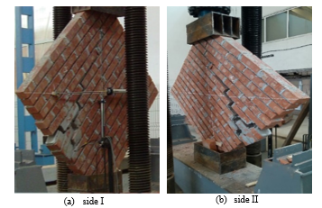 Figure 1: Failure mode of unreinforced masonry wall
The failure of the second specimen (W-1D-CFRP) started gradually by continuous diagonal shear cracking that propagates along the brick surface and across the mortar, accompanied by delamination in several points on the diagonal CFRP wrap and finished by the detachment of a considerable part of the wall and the shear slippage of a layer of masonry substrate at one edge. The stability of the wall reduced even after stopping the test, the specimen collapse and presented a potential danger figure 2.
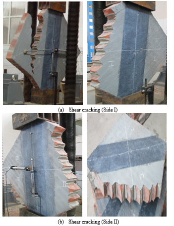 Figure 2: Failure mode of W-1D-CFRP
However, the use of CFRP wrap enhanced the strength and the stiffness of the wall. The peak load reached, in this case, is 23KN, which presents an increase by a factor of 2.5 when it compared to URM. When the third case (W- 3D-CFRP) reached the ultimate load bearing capacity, which is equal to 37.8 KN, cracks initiated simultaneously from opposite directions parallel to the vertical compression loading, although due to the interface between masonry wall and CFRP wrap, the shear force transmitted to the diagonal CFRP wrap, which was cracked too. The behavior, in this case, is similar to equivalent diagonal strut, which was performed by the appearance of cracks between the two opposite loading shoes corners. An increase in shear strength, deformation, energy dissipation and carrying capacity of masonry wall were observed. Besides, the failure of the specimen is occurred in a high compression load started by successive cracks in masonry followed by delamination in the strengthening system. Consequently, a sudden descent in strength provided figure 3.
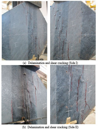 Figure 3: Failure mode of W- 3D-CFRP
For the fourth specimen (W-2DX-CFRP), no cracks observed during the test, indeed they were produced directly after wall reached its maximum load bearing capacity 27.4KN, accompanied by the delamination of CFRP wrap located at several points on the vertical diagonal direction. The failure of the surfaces of some bricks in the bottom and in the top corners of walls was observed figure 4.
The last specimen (W-2DX-2V-CFRP) reached the highest compression strength, and the maximum load bearing capacity of 39KN without failure. Indeed delamination of CFRP wrap occurred in the center of the wall and propagated along the diagonals in two directions, although no damages were remarked in the vertical layers. In addition, diagonal cracks developed along the diagonal loading direction. The specimen had similar behavior on its both sides figure 5.
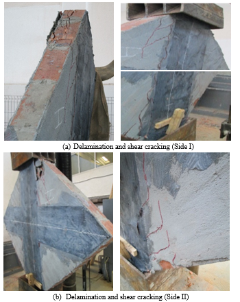 Figure 4: Failure mode of W- 2DX-CFRP
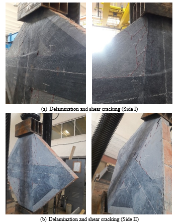 Figure 5: Failure mode of W- CFRP-W 1
4.2. Shear Stress-Strain Curves
According to ASTM E519-02 [22], the shear stress and strain for the tested specimens are calculated by the following formulas:
Where, is the shear stress, MPa; P is the applied load, N; is the crossed area of the specimen, mm² which calculated by the following formulas:
Where W and h correspond to the width and the height of the specimen in mm; t presents the total thickness of specimen, mm; and n is the percent of the gross area of the unit that is solid, expressed as a decimal.
The shear strain is calculated as follows:
Where is the vertical strengthening, mm; and is the horizontal strengthening, mm; and g is the vertical gage length, mm.
The modulus of rigidity G or modulus of elasticity in shear is calculated by:
A general overview of the experimental results, including displacements, the ultimate load and their corresponding strain and stress values were presented in the table 5.
The figure 6 and figure 7 present the shear stress-strain curves of the tested walls characterized by a serial increase and decrease due to the successive cracks propagated in masonry and transmitted to CFRP wrap.
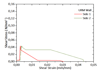 Figure 6: Shear Stress-Strain curves of the reference URM wall
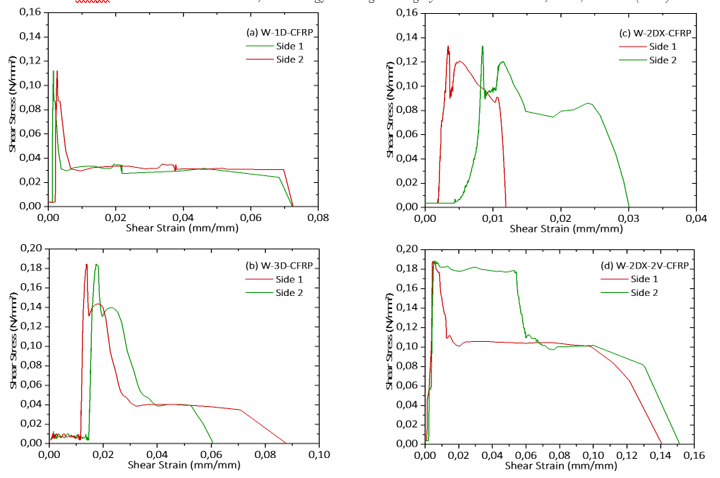 Figure 7: Shear Stress-Strain curves of the retrofitted walls
|
|||||||||||||||||||||||||||||||||||||||||||||||||||||||||||||||||||||||||||||||||||||||||||||||||||||||||||||||||||||||||||||||||||||||||||||||||||||||||||||||||||||||||||
5. Discussion
The seismic performance of URM walls relays on the capacity of CFRP wrap to maintain the stability and avoid failure. Retrofitted walls exhibited a high resistance to shear failure, characterized by the appearance of cracks either in the steel shoes corners or in the loading direction.
The use of the reinforcement system improved the integrity, the strength and the peak loading capacity of URM walls from 9.3KN to 39KN. All the specimens had a linear behavior in the beginning until they reached the maximum force, then serial cracks and delamination occurred at several points providing an important decrease in stiffness until the shear strength reached its maximum.
In all cases, the CFRP wrap reduced walls damages and enhanced safety. Indeed, each configuration influenced in a different way the behavior of URM wall. The failure of W-1D-CFRP is characterized by a brittle behavior and a shear failure caused by serial cracks followed by the detachment of a large part of the specimen.
The W-2DX-2V-CFRP configuration had the highest shear strength even after the specimen failure the wall remains stable, nevertheless, it presents an expensive solution in comparison to W-3D-CFRP, which had a significant shear strength and require a less ratio of CFRP wrap.
The use of CFRP wrap is recommended to minimize wall damages and increase the shear resistance of URM structures. The combination of vertical and horizontal configuration provides the highest shear resistance. Consequently, CFRP wrap presents an effective solution to upgrade the integrity and the seismic response of URM.
6. Conclusions
Five standardized walls were built using clay brick units, one was considered as reference and others were retrofitted by different configurations of CFRP wraps. The diagonal tensile strength of the specimens was evaluated through diagonal compression tests. This experimental research led to the following results:
- The reference wall showed a fragile behavior with a less shear strength values.
- The failure of the retrofitted panels started in all cases by progressive cracks in masonry, which behaved as one element due to the presence of CFRP wrap, their reactions to in-plane loading depends on the retrofitting configuration, which was observed such as a de-bonding, rupture, and delamination of CFRP wrap in diverse point of masonry wall.
- Due to the epoxy used in the interfaces, a partial delamination was observed in some cases and all the specimens had high strength, even after they reach their maximum strength, the tested specimen remains stable without collapsing.
- The retrofitting system restrains the URM wall from shear failure and shear sliding; it enhanced their strength up to 319%.
- All the used configurations, improved considerably the load bearing capacity of the specimens from 2.5 to 4.2 times.
- Despite the small ratio of reinforcement used in some cases like the specimen W-3D-CFRP; it achieves a high load bearing capacity of 37.8 KN when it’s compared to the specimens W-DX-CFRP and W-2DX-2V-CFRP, with CFRP wrap ratios of 74% and 90%, which reached the following load bearing capacities of 27.4KN and 39KN.
- The configurationW-2DX-2V-CFRP attained the highest shear strength to in-plane loading. However, results show that the best cost improvement ratio is in configuration W-3D-CFRP, which has increased the strength of the wall by 306% by deploying only a ratio of 53% of CFRP wrap.
- aAn interesting relation is remarked between the disposition of CFRP wrap, the shear strength and the stiffness of the walls.
- The FRPs retrofitting systems are effective in increasing the in-plane strength and the deformability of URM walls.
- The compressive strength of the strengthened walls had experimentally observed to be 147.31% to 319.35% higher than URM wall.
Conflict of Interest
The authors declare no conflict of interest with any individual or organization.
Acknowledgments
The authors acknowledge the support and the assistance afforded by SIKA Iasi.
- K. Lang, “Seismic vulnerability of existing buildings. PhD dissertation, Institute of Structural Engineering”. Department of Civil, Environmental and Geomatics Engineering., Swiss Federal Institute of Technology, Zurich, Switzerland, 2002.
- S. El Malyh, A. Bouyahyaouo, T. Cherradi, “Review on influence of infilled on the seismic behavior of frame structures”. Journal of Engineering and Applied Sciences, 14(2), 356-372, 2019. DOI: 10.36478/jeasci.2019.356.372.
- ICC Evaluation Service, “Acceptance criteria for masonry and concrete strengthening using fiber reinforced cementitious matrix (FRCM) composite systems” Tech. Rep. AC434, ICC Evaluation Service, Whittier, Calif, USA, 2013.
- Babaeidarabad, F. De Caso, A. Nanni, “URM walls strengthened with fabric-reinforced cementitious matrix composite subjected to diagonal compression”. Journal of composites for Construction, 18(2), 2013. DOI: 10.1061/(ASCE)CC.1943-5614.0000441
- Prota, G. Marcari, G. Fabbrocino, G. Manfredi, C. Aldea, “Experimental in-plane behavior of tuff masonry strengthened with cementitious matrix-grid composites.” Journal of composites for Construction, 10(3), 223-223, 2006. DOI:10.1061/ (ASCE)1090-0268(2006)10:3(223)
- ElGawady, P. Lestuzzi, M. Badoux, “A review of conventional seismic retrofitting techniques for URM”. In: proceedings of 13th international brick and block masonry conference. Amsterdam, July 4-7, 2004.
- G. Tumialan, N. Galati, A. and Nanni, “Fiber-reinforced polymer strengthening of unreinforced masonry walls subject to out of-plane loads.” ACI Structural Journal, 100(3), 312–329, 2003.
- Santa María, G. Duarte, A. Garib , “Experimental investigation of masonry panels externally strengthened with CFRP laminates and fabric subjected to in-plane shear load”. 13th WorldConference on Earthquake Engineering Vancouver, B.C., Canada, August 1-6, 2004.
- Bruneau, “State-of-the-art report on seismic performance of unreinforced masonry buildings”. Journal of Structural Engineering, 120 (1), 230–251, 1994.
- Capozucca, “Experimental analysis of historic masonry walls reinforced by CFRP under in-plane cyclic loading”. Composite Structures, 94(1), 277-289, 2011. DOI: 10.1016/j.compstruct.2011.06.007.
- P. Russell, “Characterization and seismic assessment of unreinforced masonry buildings,” Ph.D. thesis, University of Auckland, New Zealand, 2010.
- Zhuge, “FRP Retrofitted URM walls under in-plane shear: review and assessment of available models”. Journal of Composites for Construction, 14(6), 743–753, 2010.
- R. Ehsani, H. Saadatmanesh, A. Al-Saidy, “Shear behavior of URM retrofitted with FRP overlays”. Journal of Composites for Construction, 1(1), 1997. https://doi.org/10.1061/(ASCE)1090-0268(1997)1:1(17)
- Bosiljkov, A. W. Page, V. Bokan-Bosiljkov, R. Zarnic, “Performance based studies of in-plane loaded unreinforced masonry walls”. Masonry International, 16 (2), 39–50, 2003.
- Benedetti, E. Steli, “Analytical models for shear-displacement curves of unreinforced and FRP reinforced masonry panels”. Construction and Building Materials, 22(3), 175–185, 2008. DOI: 10.1016/j.conbuildmat.2006.09.005.
- H. Salmanpour, N. Mojsilovic, J. Schwartz, “Deformation capacity of unreinforced masonry walls subjected to in plane loading: A state-of-the-art review”. International Journal of Advanced Structural Engineering, 22, 2013. https://doi.org/10.1186/2008-6695-5-22
- Magenes, G. M. Calvi , “In-plane seismic response of brick masonry walls”. Earthquake Engineering and Structural Dynamics, 26(11), 1091-1112, 1997. https://doi.org/10.1002/(SICI)1096-9845(199711)26:11<1091::AID-EQE693>3.0.CO;2-6
- Stratford, G. Pascale, O. Manfroni, B. Bonfiglioli, “Shear strengthening masonry panels with sheet glass-fiber reinforced polymer”. Journal of Composites for Construction, 8(5), 434-443, 2004. https://doi.org/10.1061/(ASCE)1090-0268(2004)8:5(434)
- Mosallam, S. Banerjee, “Enhancement in in-plane shear capacity of unreinforced masonry (URM) walls strengthened with fiber reinforced polymer composites Composites”. 42(6), 1657-1670, 2011. DOI: 10.1016/j.compositesb.2011.03.015
- M. C. Konthesingha, M. J. Masia, R. B. Petersen, N. Mojsilovic, G. Simundic, A. W. Page, “Static cyclic in-plane shear response of damaged masonry walls retrofitted with NSM FRP strips – An experimental evaluation”. Journal of Engineering Structures, 50, 126-136, 2013. https://doi.org/10.1016/j.engstruct.2012.10.026
- Gharib, A. Gabor, E. Ferrier, “Analyse expérimentale du comportement au cisaillement des murs en maçonnerie de pierre renforcés par matériaux composites TRC & NSM FRP”. 33èmes Rencontres de l’AUGC, ISABTP/UPPA, May 2015.
- ASTM E 519-02, Standard test method for diagonal tension (Shear) in masonry assemblages. ASTM International, West Conshohocken, PA, 2002.
- ISO 10618, Carbon fiber- Determination of tensile properties of resin-impregnated yarn, 2004.
- EN 2561, Carbon fiber reinforced plastics. Unidirectional laminates. Tensile test parallel to the fiber directions, 1995.
- EN 1015-11, Methods of Test for Mortar for Masonry – Part 11: Determination of Flexural and Compressive Strength of Hardened Mortar. European Committee for Standardization, Brussels, 1993.
- ASTM C109/C109M, Standard Test Method for Compressive Strength of Hydraulic Cement Mortars (Using 2-in. or [50 mm] Cube Specimens). ASTM International, American Society for Testing and Materials. West Conshohocken, PA, 2016.
- ASTM C-67, Standard Test Methods for Sampling and Testing Brick and Structural Clay Tile. ASTM International, American Society for Testing and Materials, West Conshohocken, PA, 2005.
- ASTM C-1314-02a, Standard Test Method for Compressive Strength of Masonry Prisms, ASTM International, American Society for Testing and Materials. West Conshohocken, PA, 2002.
- ASTM C952, Standard Test Method for Bond strength of Mortar to masonry Units. ASTM International, American Society for Testing and Materials, West Conshohocken, PA, 2002.