
Shear Strength of Unreinforced Masonry Walls Retrofitted with CFRP
Volume 5, Issue 2, Page No 351-359, 2020
Author’s Name: Sanaa El Malyh1,a), Azzeddine Bouyahyaoui1, Toufik Cherradi1, Ancuta Rotaru2, Petru Mihai3
View Affiliations
1Department of Civil Engineering, Mohammadia School of Engineer, Mohammed V University of Rabat, Morocco.
2Department of Transportation Infrastructure and Foundations, Gheorge Asachi Technical University of Iasi, Faculty of Civil Engineering and Building Services, Romania.
3Department of Concrete Structures, Building Materials, Technology and Management, Gheorge Asachi Technical University of Iasi, Faculty of Civil Engineering and Building Services, Romania.
a)Author to whom correspondence should be addressed. E-mail: selmalyh@gmail.com
Adv. Sci. Technol. Eng. Syst. J. 5(2), 351-359 (2020); ![]() DOI: 10.25046/aj050246
DOI: 10.25046/aj050246
Keywords: Stiffness, Strengthening, Composite materials, Carbon fiber reinforced polymer, Unreinforced masonry wall

Export Citations
This paper investigates the in plane behavior of unreinforced masonry (URM) walls externally strengthening on both sides by different configurations of unidirectional carbon fiber reinforced polymer (CFRP) wraps. In order to evaluate the effectiveness of using the strengthening systems to improve the in plane behavior of masonry walls, the experimental program was conducted by testing four specimens. Initially, URM wall without retrofitting system; considered as a reference; was tested. The other specimens were retrofitted on both sides by different configurations of unidirectional CFRP wraps. Walls were tested following diagonal tensile (shear) test method. Then the effect of position, spacing, and reinforcement ratio on ductility, stiffness, shear behavior and failure modes of URM wall were evaluated. Experimental results confirmed the effectiveness of using CFRP in improving energy dissipation, strength, stiffness and ductility of URM wall. Furthermore, the strengthening system affected in a direct way the shear capacity and the deformability of URM walls.
Received: 14 February 2020, Accepted: 19 March 2020, Published Online: 26 March 2020
1. Introduction
URM walls are widely used in many structures around the world due to many factors, like cost-effective, time of construction and durability; they are constructed by using different materials (bricks, stones, mortar, etc.,). The interaction between their different elements influence in a direct way their behavior, which is characterized, in the most cases by diagonal shear failures, sliding shear deformations and compression failures [1]. The seismic assessment of existing buildings in Basel indicates that during a moderate earthquake about 45% to 80% of existing URM buildings will experience damages grade 4, equivalent to heavy damage or grade 5 which correspond to destruction [2].
URM walls still have many limitations; they are sensitive to shear and tensile forces produced by seismic loads. Besides, after earthquakes, several damages were occurred in buildings; but the most important ones were located in URM walls [3]. The fact that URM walls are more vulnerable to damage during earthquakes, push many researchers to investigate the influence of vertical compression due to different loads, in plane and out of plane lateral loading on unreinforced masonry walls [4]. The infill panel damage depends on various parameters, for [5], it is related to the lack of connection between crossing walls, improper location and dimensions of openings. On the other hand, for [6], it depends on many factors, but in most cases, it is related to the use of inappropriate materials, inadequate masonry units, incorrect cross section of the wall, irregular wall openings and improper roofing.
However, the probability of out of plane failure enhances because of the inappropriate connections between crossing walls, openings placement and the absence of connecting units between external and internal leaves of the wall sections [7]. The masonry piers subjected to in plane-loading shows different types of failure mechanisms [8], the first type is rocking failure, which appears when the horizontal load increase, it is characterized by bed joints cracks in tension, shear that appears by the compressed masonry and finally by the overturning of the wall and simultaneous crushing of the compressed corners. The second type is shear cracking, appeared when the inclined diagonal cracks performed at peak resistance. For the last failure mechanism, it performed when walls under reversed seismic loading show important sliding planes, which developed in bed joints with tensile horizon cracks. The shear compression behavior of unreinforced masonry walls was studied also by [9]; the results show that the comportment of brick masonry walls under seismic loading is influenced by their height/width ration and by the vertical stress. Under seismic loading, URM walls show a strong degradation in stiffness and strength, which produced many damages in buildings. In literature the behavior of URM walls, and especially when it was considered as compression elements had been widely studied, furthermore, the necessity of using FRP as strengthening systems to reinforce URM walls with FRP was investigated by many researchers [10]-[15], also, their effectiveness in reinforcing masonry structures was highlighted by [16]-[18]. Sheets of unidirectional carbon fiber or glass fiber placed on two sides of the walls, which were subjected to diagonal compression to determine the shear strength and shear elastic modulus of retrofitted masonry walls; results indicate an increase of 55% of strength [19]. For [20], the application of fiber reinforced polymer grids to new or existing buildings is very easy and cheap, it permits to enhance strength and energy dissipation. Other researchers [21] tested URM clay units walls retrofitted by FRP composites rods and laminates under diagonal loading to deduce their shear performance. Rods were placed on masonry bed joints. The pseudo-ductility and the shear capacity increases up to 200%. One-side strengthened walls did not indicate an important increase in pseudo-ductility. However, for two-sides symmetrical strengthening, wall results show an increase in the ultimate load and the pseudo-ductility.
The shear collapse mechanisms of one face retrofitted panels reinforced with different configuration FRP laminates subjected to diagonal compression was not remarkably modified. However, the two-side retrofitted panels show less brittle failure and an increase in the ultimate capacity [22]. Additional researchers [23] tested panels retrofitted on one side by cementitious matrix grid composite (CMG) system, results indicate that at the ultimate stage, the cracks did not pursue the line of action of the splitting load but they follow the line of minimum resistance. The failure of some panels appeared in bed and head joint of mortar, for the shear-capacity, it was characterized by the feeble connection between mortar and units-Tuff stones, but the failures of other panels were characterized by debonding along the mortar joints forming a stepped appearance. Comparing the efficiency of different configurations of reinforcing systems applied on URM, the full surface coverage and inclined plates retrofitting systems are the most effective configurations [24].
The principal alternative of FRP is an innovative composite materials system, and particular type of textile-reinforced mortar (TRM) it’s a Fabric Reinforced Cementitious Matrix (FRCM) material, which contain fibers embedded into an inorganic matrix, that characterized by better homogeneity with masonry because of its small content of polymeric resin. There is different type of FRCM that depends in which type of textiles they were produced (steel, glass, basalt, carbon, aramid. etc.) and depends on the textile characteristics (unidirectional or bi-directional). FRCM system had been studied by many researchers [25] and [26], which studied experimentally FRCM material that constituted from dry fiber grid in inorganic matrix with short fibers in tensile and bond. In addition, [27] performed a shear test on historic walls strengthened by means of jacketing with GFRP (Glass Fiber Reinforced Plastics) mesh, implanted in an inorganic matrix; results had shown an important amelioration in lateral load-carrying capacity of up to 1060% while compared to the control panels, in addition, the shear parameters were identified by [28, 29-30]. The behavior of half-scale single leaf unreinforced masonry walls retrofitted by composite (URM-WRC) was tested under dynamic in-plane loading to analyze the behavior of URM walls with and without composite material [31]. [32] Had used a recent retrofitting technique in URM walls, which was tested under diagonal compressive force, results show that FRP systems enhance the shear strength of the walls.
Recently, NSM FRP attracted an important amount of researchers, because it affords important advantages. Usually, it used to retrofit reinforced concrete structures. The NSM procedure starts with surface preparation, groove sawing and application of the adhesive. This technique has a high adherence with retrofitted surface, and more protected by the material that cover the NSM material from different type of damages. The NSM FRP system is better than externally bonded FRP [33]. For [34], the bond behavior of FRP-concrete depends on the strength of the concrete and the adhesive, cross-section of retrofit system (FRP), spacing between FRP reinforcement and concrete edge, also by spacing between FRP, bond length and characteristics of different types of materials. In regards to NSM method, the most effectiveness retrofitting systems to work with is thin rectangular strip because it has many advantages, like decreasing of debonding, and increasing confinement around the thin rectangular strip [35].
2. Experimental Program
2.1. Materials Characterization
Clay brick units were tested under uni-axial compressive machine in accordance with ASTM C67 [36]; the average compressive strength is 11.28N/mm², and for the maximum strain is 0.074 and the modulus of elasticity is 148.30N/mm².
For the first types of mortar used in the construction of the walls, six cubes of mortar of each type were tested under uni-axial compressive test following ASTM C109/C109M [37]. For the mortar type M5 the average compressive strength is 3.31N/mm² corresponding to strain of 0.0015 and modulus of elasticity of 2203.52N/mm². For the mortar used on the surface of the wall the average compressive strength is 13.85 N/mm², the maximum strain is 0.00038 and modulus of elasticity is 36579.18 N/mm². Following EN 1015–11 [38], nine normalized mortar specimens were tested to determine the flexural and compressive strength of mortar applied to wall sides and to bed and head joints of walls, models were tested under three-point bending, then the obtained pieces of flexural test were tested in compression. The compressive strength of the first type of mortar is equal to 4.47N/mm² and for the second type is 27.84N/mm. More details about the properties of different materials are presented in the table 1.
Sikadur 330, constituted from thixotropic epoxy based impregnating resin and adhesive, mixed in a ratio of 4:1, were used for impregnation of six CFRP coupons with dimensions of
Table 1: Details about different materials
| Material types | Dimensions (mm) | Type of test | Standard used | Compressive strength(N/mm²) |
| Mortar ( Apply on bed and head of joints) | 40*40*160 | Flexural and compression strength | EN 1015–11 | 4.47 |
| 50*50*50 | Compression strength | ASTM C109/C109M | 3.31 | |
| Mortar (Apply on wall surface) | 40*40*160 | Flexural and compression strength | EN 1015–11 | 27.84 |
| 50*50*50 | Compression strength | ASTM C109/C109M | 13.85 | |
| Clay bricks | 240*115*63 | Compression strength | ASTM C-67-05 | 11.28 |
| Masonry prism (3 units of brick linked by mortar) | 240*200*63 | Compressive test | ASTM C1314 [39] | 10.83 |
| Masonry prism (2 units of brick linked by mortar) | 240*130*63 | Bond strength of mortar-masonry | ASTM C952[40] | 17.43 |
15x250mm. First, the dry specimens were put on a thin layer of epoxy resin, which were applied on plastic fixed on regular surface, and another thin layer of epoxy applied on coupons, then second plastic used to cover the specimens. The air removed by using a grooved roller, then extra epoxy resin removed by covering specimens with a flat surface of wood. Characteristics of epoxy given by the manufacturer: for flexural E-Modulus, Tensile Strength and Tensile Modulus of Elasticity values are respectively 3800N/mm², 30N/mm² and 4500N/mm².
Tabs with dimensions of 15*56mm were fixed to all the extremities of coupons by adhesive Sikadur-30, which based on a mixture of epoxy resin and special filler in a ratio of 3:1. All the specimens were cured for seven days before being tested on a tensile machine following ASTM D3039/D3039M [41]. The table 2 presents the mechanical characteristics of CFRP used.
| Table 2: Characteristics of fibers | |||
| Material type | Fibers density | Thickness (mm) | Elongation at rupture |
|
CFRP (ISO10618) [42] |
1.82 g/cm3 | 0.129 | 1.7 % |
| Tensile strength (N/mm²) | Tensile modulus of elasticity (N/mm²) | ||
| >4000 | 230000 | ||
|
Nominal thickness (mm) |
Tensile strength (N/mm²) |
||
|
Laminate (EN 2561) [43] |
0.129 |
Average | Characteristics |
| 3500 | 3200 | ||
| Modulus of Elasticity in Tension (KN/mm²) | |||
| 225 | 220 | ||
2.2 . Preparation of Different Specimens
The experimental study passed through several stages; first, URM walls with dimension of 1200*1200*115mm were constructed by qualified masons using clay brick masonry units with dimension of 240*115*63mm, linked by a 10mm joint layer of mortar, then URM walls were cured for 28 days. The procedure of strengthening masonry walls started with surface coatings, which consist of preparing walls by cleaning the both sides of walls and especially the joints from dust with a high pressure of air. Before the application of strengthening materials, walls sides were wetted, and then a thin layer of primer and mortar of a nominal thickness of 12mm were applied to walls surfaces. The main role of primer and mortar is to provide a leveled surface of URM walls; 28 days after, different configurations of CFRP wraps were applied to wall surface after applying the first epoxy resin layer, then a second layer was used to fix CFRP wrap. Then all the strengthened walls were cured for seven days before being tested (figure 1).
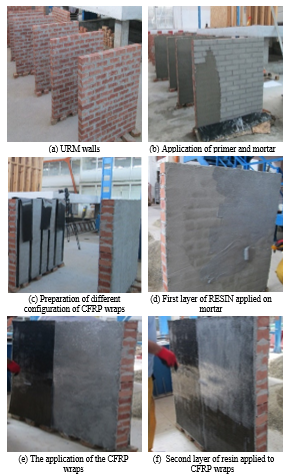 Figure 1: Different steps of retrofitting URM wall by the CFRP wraps
2.3 . Description of Different Configurations and Test Instrumentation
Details of the aforementioned walls strengthened by diverse configurations of CFRP (figure 2) are illustrated in table 3.
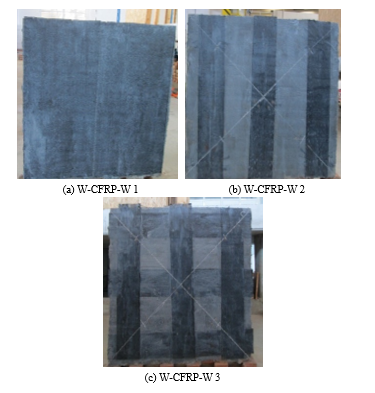 Figure 2: Specimens retrofitted with different configurations
Table 3: Retrofit details applied on each side
| Designation | Ratio (%) | Configuration |
Dimensions of CFRP (mm) |
| URM-W-R | – | – | – |
| W-CFRP-W1 | 100 | Full face | 1200*1200 |
| W-CFRP-W2 | 50 | 3 Vertical | 200*1200 |
| W-CFRP-W3 | 75 | 3Verticals & 3 horizontals | 6*(200*1200) |
* URM-W-CFRP-W-X-: URM: unreinforced masonry, W: wall, CFRP-W: carbon fiber reinforced polymer, W: wrap, X: number of wall.
After the preparation of all specimens, the next step is the determination of diagonal tensile strength of walls reinforced by CFRP. Initially, special attention was given to the specimen transportation from the construction zone to the testing machine by taking into consideration all the security measures in order to keep the same properties and avoiding any deterioration of walls. In accordance with ASTM E519-02[44], the wall was fixed between two steel shoes, which were placed on top and lower corners of the wall to permit the transmission of machine load. Then, four 500mm LVDT’s were installed on each side of the wall , to record shortening in the vertical diagonal (compression) and lengthening in the horizontal diagonal directions (traction). Before starting test of each wall, all LVDTs were calibrated. The load applied at the upper point of the wall on the vertical diagonal in the gravity direction through hydraulic jack. The fourth walls were tested by applying load continuously. Measurement of in-plane displacement of different specimens were recorded automatically through LVDTs by using special data acquisition system. The figure 3 presents the test machine and the emplacement of different equipment.
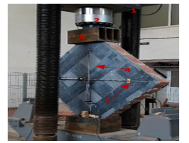 Figure 3: Setup of the diagonal tensile test: (1) Steel frame; (2) Loading plate; (3) Steel shoe; (4) Vertical LVDT; (5) Horizontal LVDT
3. Experimental Results
Four walls were tested to failure, one was considered as reference and others were retrofitted on both sides by three different configurations. For the first wall, the unidirectional CFRP wrap covered the both wall surfaces with an overlay in vertical direction of 250mm in the middle of the wall. Then, three vertical CFRP wraps with a width of 200mm and length of 1200mm were used to reinforce the second specimen. For the last wall, it was reinforced by vertical and horizontal CFRP wraps of the same dimension 200*1200mm. Failure modes and Shear stress-strain curves are described in the next part.
3.1. Test Observations
While increasing diagonal compression load applied on the first specimen (URM wall), considerable diagonal shear cracks started to propagate diagonally, from the top corner, parallel to loading direction, and across the wall width. While increasing compressive stress, the diagonal tension and the shear stress increase too, and then inclined diagonal shear cracks in bed and head joints followed by few cracks in bricks were observed. Suddenly, a brittle failure was produced by diagonal shear cracking and sliding along the mortar joints, which occur a detachment of a part of the wall (figure 4).
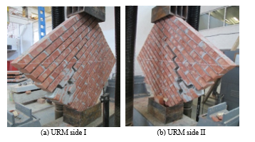 Figure 4: Failure mode of unreinforced masonry wall
For the first configuration (W-CFRP-W 1), the wall surfaces were entirely retrofitted by CFRP. It was characterized by a symmetrical behavior on its both sides. While increasing compressive loading, diagonal cracks were observed in masonry substrate and shear tensile is transferred via the interface between masonry and CFRP wrap, as a result a partial delamination of CFRP occurred in two opposite directions perpendicular to the vertical diagonal that occur the failure of tested. The CFRP shows their effectiveness in holding the masonry wall that react in this case as one element, consequently an important resistance of the tested wall to in-plane strength was observed. In addition, load-bearing capacity of both sides increased (figure 5).
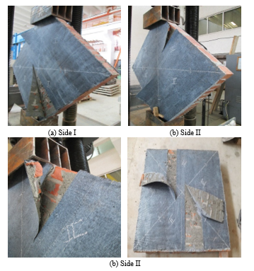 Figure 5: Failure mode of W- CFRP-W 1
For the second configuration (W-CFRP-W 2), both sides of wall were reinforced by three vertical unidirectional CFRP wraps with a width of 200mm. While increasing diagonal compression loading, the strength of wall increase too, then cracks on both sides of the wall started in masonry between each two vertical CFRP wrap, at the upper and lower corners parallel to the direction of the applied load. The cracks propagation continue in a diagonal direction until they reach the middle vertical reinforcement, which started to delaminate partially from the upper line of reinforcement until it will measure for Side I, 40 cm and for side II, 30cm. Despite the fact that bricks have many cracks, but the reinforced wall, remains stable. Furthermore, no collapse produced while transporting tested wall. Delaminating were located and observed at the end of cracked masonry that transferred tensile load via interface masonry-CFRP wrap (figure 6).
For the third configuration (W-CFRP-W 3), failure mode in the strengthened wall started by subsequent diagonal cracks in masonry and in CFRP wrap, parallel to compression load direction, which was followed by the delamination and rupture of CFRP wrap in two extremities of the wall. Moreover, a diagonal slippage of some layers situated on the top corner of the wall, which contain just one and a half brick forming a stepped appearance and causing the failure of the walls (figure 7).
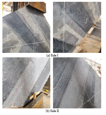 Figure 6: Diagonal shear cracking and delamination of CFRP wraps
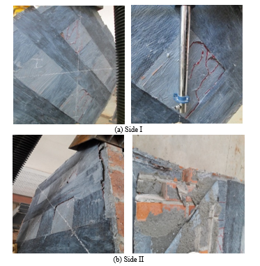 Figure 7: Diagonal shear cracking along the diagonal and delamination of CFRP wraps of the strengthened wall
3.2. Shear Stress-Strain Curves
According to ASTM E519-02 [44], the shear stress and strain for the tested specimens are calculated by the following formulas:
Where, is the shear stress, MPa; P is the applied load, N; is the crossed area of the specimen, mm² which calculated by the following formulas:
Where W and h correspond to the width and the height of the specimen in mm; t presents the total thickness of specimen, mm; and n is the percent of the gross area of the unit that is solid, expressed as a decimal.
The shear strain is calculated as follows:
Where is the vertical strengthening, mm; and is the horizontal strengthening, mm; and g is the vertical gage length, mm.
The modulus of rigidity G or modulus of elasticity in shear is calculated by:
G = , MPa.
The figure 8 illustrates the shear stress-strain curves, which were deduced following ASTM E519-02 [44].
The results of the diagonal compression tests on the fourth walls (Shear stress, shear stress, modulus of rigidity, initial and peak loads and their corresponding displacement) are illustrated in table 4.
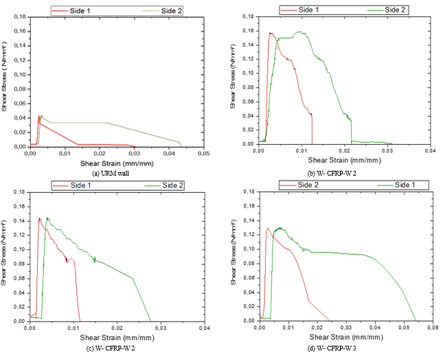 Figure 8: Shear Stress-Strain Curves of the tested specimens
4. Discussion
The wall surfaces were covered by different configurations of unidirectional CFRP wrap. The figure 8 presents the Shear Stress-Strain curves of retrofitted panels, which characterized by serial increase and decrease in the carrying load due to successive cracks propagated in masonry and transmitted to the strengthening system (unidirectional CFRP wraps). The curves shown that in the first step the behavior of all strengthened specimens depends on the beginning on the mechanical properties of masonry wall then the CFRP wrap start to react. All the tested walls were tested in compression following ASTM E519-02 [44] to determine the shear strength.
The experiment started by testing unreinforced masonry wall. The maximum compression load carried by the specimens was 9.3KN, which correspond to the following vertical and horizontal displacements, for the first side 0.62mm and 0.65mm and for the second side 1.24mm and 0.52mm. When the specimen reaches its load bearing capacity its behavior was characterized by brittle failure started from the top corner of the wall fixed on steel shoes, then the cracks propagated in bed and head joints and diagonal shear cracks were observed which cause a total detachment of an important part of URM wall.
For the second wall, both sides were entirely reinforced by unidirectional CFRP wrap, the peak compressive diagonal load supported by this specimen was 32.3KN, which associated to the following vertical and horizontal displacement, for the first side, 1.2mm and 0.18mm for the second side 4.83mm and 0.37mm. In this case, the reinforced wall had an important strength in compression and in tension; furthermore the behavior of this specimen was characterized by a high ductility and an increase in energy dissipation. Then when the wall reached its maximum load bearing capacity, its strength decrease and cracks initiated from the top and propagated until reaching the bottom of the wall along the loading direction, then the unidirectional CFRP wrap partially delaminate in opposite directions consequently the compressive strength decreased.
The third tested Wall, was reinforced on each side by three vertical symmetrical layers of unidirectional CFRP wrap, its failure occurred by successive diagonal cracks parallel to load direction and across the bed and head joints. The cracks appeared between the two parallel layers on the top corner of the wall, and then it propagated until reaching the bottom of the wall and appeared between the other parallel layers. Some cracks appeared in the layer situated in the middle of the wall, which start to delaminate from its mid-height. The specimen reaches 29.4KN corresponding to the vertical and horizontal displacement, for side one 1.03mm and 0.15mm and for the second side 1.9mm and 1mm, which present an increase of more than 3 times in peak load capacity when it’s compared to the URM wall.
The last specimen is characterized by less load bearing capacity, equal to 26.2KN corresponding to the vertical and horizontal displacement, for the first side 1.02mm and 0.7mm and for the second side, 1.46mm and 3.02mm. In this case, the failure mechanism, diagonal shear cracking initiated along the mortar joints and bricks on the direction of the applied load followed by the delamination of unidirectional CFRP wrap, and then a detachment of the top corner of wall accompanied by a high decrease in strength were observed.
5. Conclusions
This study presented the experimental results of three masonry walls retrofitted by using different configurations of the CFRP wrap under diagonal compression were investigated to evaluate the influence of the strengthening system on energy dissipation, stiffness and strength. Based on the experimental results the following conclusions can be drawn:
- The first results of URM wall tested under compression loading were characterized by brittle behavior due to the feeble strength of mortar joints when it is compared to the bricks, which occur a shear slip failure accompanied in some case by some cracks in the masonry substrate.
- All retrofitted walls showed a high ductility and an increase in energy dissipation in the beginning, furthermore similar behavior before failure initiated by progressive cracks in masonry, which behave as one element due to the presence of CFRP wrap, that had different reactions to compression loading. Such as a de-bonding, rupture, and delamination from a different point of masonry wall, finished in all the cases by failure. Different failure modes were remarked in the test such as shear cracking, brittle failure, compression strut, delamination, shear sliding.
- The experimental results shows that the retrofitted walls exhibited a high resistance to shear failure. The load bearing capacity of the strengthened walls increased from 26.2KN to 32.3KN when it compared to URM wall, which equal to 9.3KN.
- For the configuration type 1 and type 2, while increasing loading, diagonal shear cracks started along the mortar joints, then the failure resulted immediately after rupture and delamination of the strengthening system. They had a high shear strength, stiffness and ductility; moreover, even after their failure the walls remain stable.
- The results of configuration type 2 with reinforcement ratio of 50% had significant ductility and deformability, despite the small ratio used of CFRP wrap, the diagonal tension characteristics were improved, which prove that the strength of strengthened wall depends not only on reinforcement ratio but also on the position and direction of the strengthening system.
- The configuration type three, strengthened by 75% of strengthening system had less energy absorption capacity and a feeble strength against the compression loading when it compared to the other configurations. In addition, it was characterized by a brittle behavior caused by serial cracks followed by the failure of a part of the wall. This configuration presents less safety, which make its amelioration necessary.
- For the strain-stress curves show in the beginning of the test a linear behavior of the specimens followed by the nonlinear behavior when the specimen reaches their maximum carrying capacity. Consequently, the failure of the retrofitted specimens had occurred when the masonry substrate attained its peak load bearing capacity, then the CFRP wrap start to keep the masonry as one unit and absorb the tensile compression through energy transmitted by masonry via the interface mortar and resin.
- Retrofitting materials with their tensile strength capacity augment deformations ability of URM wall by holding them. This study showed the efficiency of the strengthening system in enhancing security of structures during an earthquake by improving the compression strength, energy dissipation, stiffness and ductility of URM wall. The compressive strength of the strengthened walls had experimentally observed to be 181.72% to 247.31% higher than URM wall.
- Additional experimental investigations will present the next phase of research.
Conflict of Interest
The authors declare no conflict of interest with any individual or organization.
Acknowledgments
The authors acknowledge the support and the assistance afforded by SIKA Iasi.
- S. El Malyh, A. Bouyahyaouo, T. Cherradi, “Review on influence of infilled on the seismic behavior of frame structures” Journal of Engineering and Applied Sciences., 14(2), 356-372, 2019. DOI: 10.36478/jeasci.2019.356.372.
- Lang K., Seismic vulnerability of existing buildings, PhD thesis. Institute of Structural Engineering Swiss Federal Institute of Technology, Zurich, Switzerland, 188, 2002.
- D’Ayala D.F., Paganoni S., Assessment and analysis of damage in L’Aquila historic city centre after 6th April 2009, Bulletin of Earthquake Engineering, Vol 9, Issue 1, 2011, pp. 81-104.
- Kaplan H., Bilgin H., Yilmaz S., Binici H., Öztas A., Structural damages of L’Aquila (Italy) earthquake, Natural Hazards and Earth System Sciences, Vol 10, Issue 3, 2010, pp. 499-507.
- Inel M., Ozmen H. B., Akyol E., Observations on the building damages after 19 May 2011 Simav (Turkey) earthquake, Bulletin of Earthquake Engineering, Vol 11, Issue 1, 2013, pp. 255-283.
- Tama Y. S., Solak A., Cetinkaya N., Sen G., Yilmaz S., Kaplan H., Damages to unreinforced masonry buildings by the Van earthquakes of 23 October and 9 November 2011, Natural Hazards and Earth System Sciences, Vol 13, Issue 2, 2013, pp. 329-337.
- Cetinkaya N., Turkmen I, Damages of Masonry School Buildings on 2010 Karakocan-Elazig Earthquake, International Balkans Conference on Challenges of Civil Engineering, 2011.
- Magenes G., Calvi G. M., In-plane seismic response of brick masonry walls. Earthquake engineering & structural dynamics, Vol 26, Issue 11, 1997, pp. 1091-1112.
- Anthoine A., Magonette G., Magenes G., Shear-compression testing and analysis of brick masonry walls, in : Proceedings of the 10th European Conference on Earthquake Engineering, Vol 3, 1995, pp. 1657-1662.
- Bilotta A., Ceroni F., Lignola G.P., Prota A., Use of DIC technique for investigating the behaviour of FRCM materials for strengthening masonry elements, Composites Part B : Engineering, Vol 129, 2017, pp. 251-270.
- Guerreiro J., Proença J., Ferreira J. G., Gago A., Experimental characterization of in-plane behaviour of old masonry walls strengthened through the addition of CFRP reinforced render, Composites Part B Engineering, Vol 148, 2018, pp. 14-26.
- Ismail N., Ingham J., Polymer textiles as a retrofit material for masonry walls. Proceedings of the Institution of Civil Engineers, Journals of Structures & Buildings, Vol 167, 2014, pp. 15-25.
- Jafari A., Oskouei A.V., Bazli M., Ghahri R., Effect of the FRP sheet’s arrays and NSM FRP bars on in-plane behavior of URM walls, Journal of Building Engineering, Vol 20, 2018, pp. 679-695.
- Mantegazza G., Gatti A., Barbieri A., Retrofitting concrete and masonry building: FRCM a new emerging technology, XII Konferencja Naukowo-Techniczna Problemy Remontowe W Budownictwie Ogólnymi Obiektach Zabytkowych REMO, 2006, pp. 6-8.
- Marcari G., Manfredi G., Prota A., Pecce M., In-plane shear performance of masonry panels strengthened with FRP, Composites Part B : Engineering, Vol 38, Issues 7-8, 2007, pp. 887-901.
- Fam A.Z., Rizkalla S.H., Tadros G., Behavior of CFRP for prestressing and shear reinforcements of concrete highway bridges, ACI Structural Journal, Vol 94, Issue 1, 1997, pp. 77-86.
- Grande E., Imbimbo M., Sacco E., Bond behaviour of CFRP laminates glued on clay bricks : experimental and numerical study, Composites Part B : Engineering, Vol 42, Issue 2, 2011, pp. 330-340.
- Triantafillou T.C., Strengthening of masonry structures using epoxy-bonded FRP laminates, Journal of composites for construction 2, Vol 2, Issue 2, 1998, pp. 96-104.
- Borri A., Corradi M., Vignoli A., Seismic upgrading of masonry structures with FRP, in: 7th International Conference on Inspection Appraisal Repairs and Maintenance of Buildings and Structures, Nottingham, United Kingdom, 2001, pp. 43-54.
- Sofronie R.A., Seismic strengthening of masonry in buildings and cultural heritage, in: 6th National Congress on Seismology and Seismic Engineering, 2004, pp. 81–100.
- Grando S., Valluzzi M.R., Tumialan J.G., Nanni A., Shear strengthening of URM clay walls with FRP systems, in:Fibre-Reinforced Polymer Reinforcement for Concrete Structures: World Scientific, Vol 2, 2003, pp. 1229–1238.
- Valluzzi M.R., Tinazzi D., Modena C., Shear behavior of masonry panels strengthened by FRP laminates, Construction and Building materials, Vol 16, issue 7, 2002, pp. 409-416.
- Prota A., Marcari G., Fabbrocino G., Manfredi G., Aldea C., Experimental in-plane behavior of tuff masonry strengthened with cementitious matrix–grid composites, Journal of Composites for Construction, Vo 10, Issue 3, 2006, pp. 223-233.
- ElGawady M., Lestuzzi P., Badoux M., A review of retrofitting of unreinforced masonry walls using composites, in: Proc., 4th International Conf. on Advanced Composite Materials in Bridges and Structures. CSCE, 2004.
- Nanni A., A new tool for concrete and masonry repair. American Concrete Institute (ACI), Vol 34, Issue 4, 2012, pp. 43–49.
- Carozzi F.G., Bellini A., D’Antino T., de Felice G., Focacci F., Hojdys L., Laghi L., Lanoye E., Micelli F., Panizza M., Experimental investigation of tensile and bond properties of Carbon-FRCM composites for strengthening masonry elements, Composites Part B: Engineering, Vol 128, 2017, pp. 100-119.
- Corradi M., Borri A., Castori G., Sisti R., Shear strengthening of wall panels through jacketing with cement mortar reinforced by GFRP grids, Composites Part B : Engineering, Vol 64, 2014, pp. 33-42.
- Arboleda D., Loreto G., De Luca A., Nanni A., Material characterization of fiber reinforced cementitious matrix (FRCM) composite laminates, in: Proceedings of 10th International Symposium on Ferrocement and Thin Reinforced Cement Composite, Havana, Cuba, October, 2012, pp. 12-17.
- Calderini C., Cattari S., Lagomarsino S., The use of the diagonal compression test to identify the shear mechanical parameters of masonry, Construction and building materials, Vol 24, Issue 5, 2010, 2010, pp. 677-685.
- Rilem T.C., LUM B6 Diagonal tensile strength tests of small wall specimens, 1991, RILEM Recommendations for the testing and use of constructions materials, 1994, pp. 488-489.
- ElGawady M.A., Lestuzzi P., Badoux M., Aseismic retrofitting of unreinforced masonry walls using FRP, Composites Part B: Engineering, Vol 37, Issue 2-3, 2005, pp. 148-162.
- Mahmood H., Ingham J.M., Diagonal compression testing of FRP-retrofitted unreinforced clay brick masonry wallettes, Journal of Composites for Construction, Vol 15, Issue 5, 2011, pp. 810-820.
- Oehlers D.J., Rashid R., Seracino R., IC debonding resistance of groups of FRP NSM strips in reinforced concrete beams, Construction and Building Materials, Vol 22, Issue 7, 2008, pp. 1574 -1582.
- Seracino R., Jones N.M., Ali M.S., Page M.W., Oehlers DJ, Bond strength of near-surface mounted FRP strip-to-concrete joints, Journal of Composites for Construction, Vol 11, Issue 4, 2007, pp. 401–409.
- De Lorenzis L., Teng J.G., Near-surface mounted FRP reinforcement: An emerging technique for strengthening structures, Composites Part B: Engineering, Vol 38, Issue 2, 2007, pp. 119–143.
- ASTM C-67, Standard Test Methods for Sampling and Testing Brick and Structural Clay Tile. ASTM International, American Society for Testing and Materials, West Conshohocken, PA, 2005.
- ASTM C109/C109M, Standard Test Method for Compressive Strength of Hydraulic Cement Mortars (Using 2-in. or [50 mm] Cube Specimens). ASTM International, American Society for Testing and Materials. West Conshohocken, PA, 2016.
- EN 1015-11, Methods of Test for Mortar for Masonry – Part 11: Determination of Flexural and Compressive Strength of Hardened Mortar. European Committee for Standardization, Brussels, 1993.
- ASTM C-1314-02a, Standard Test Method for Compressive Strength of Masonry Prisms, ASTM International, American Society for Testing and Materials. West Conshohocken, PA, 2002.
- ASTM C952, Standard Test Method for Bond strength of Mortar to masonry Units. ASTM International, American Society for Testing and Materials, West Conshohocken, PA, 2002.
- ASTM D 3039/D 3039M, Standard Test Method for Tensile Properties of Polymer Matrix Composite Materials. ASTM International, American Society for Testing and Materials, West Conshohocken, PA, 2000.
- ISO 10618, Carbon fiber- Determination of tensile properties of resin-impregnated yarn, 2004.
- EN 2561, Carbon fiber reinforced plastics. Unidirectional laminates. Tensile test parallel to the fiber directions, 1995.
- ASTM E 519-02, Standard test method for diagonal tension (Shear) in masonry assemblages. ASTM International, West Conshohocken, PA, 2002.