
Antenna Radiation Performance Enhancement Using Metamaterial Filter for Vehicle to Vehicle Communications Applications
Volume 5, Issue 2, Page No 344-350, 2020
Author’s Name: Marwa Daghari1,a), Hedi Sakli1,2
View Affiliations
1MACS Research Laboratory LR16ES22, National Engineering School of Gabes, Gabes University, 6029 Gabes, Tunisia
2EITA Consulting, 5 Rue du Chant des oiseaux, 78360 Montesson, France
a)Author to whom correspondence should be addressed. E-mail: marwadaghari@gmail.com
Adv. Sci. Technol. Eng. Syst. J. 5(2), 344-350 (2020); ![]() DOI: 10.25046/aj050245
DOI: 10.25046/aj050245
Keywords: Metamaterial, Frequency Selective Surface FSS, Antenna, V2V communications

Export Citations
In this work, an integrated metamaterial filter design in close proximity with monopole antenna is proposed for vehicular communication applications. A cylindrical screen formed by an array of metamaterial cells is designed to be reflective at 5.9 GHz in order to enhance antenna performance in intelligent vehicle transport systems. The unit cell proposed design based on Frequency Selective Surface (FSS) is made of a square loop element glued to a thin substrate to ensure a band-stop filtering behavior. This geometry is symmetrical providing the advantage of polarization independency and exhibiting angular stability up to 45◦ for both Transverse Electric (TE) and Transverse Magnetic (TM) modes. More importantly, antenna gain and directivity enhancement are illustrated when the cylindrical FSS layer is added at a small distance from the monopole radiator. Antenna bandwidth reduction is also detected due to the presence of the added FSS layer which is suitable for Vehicle to Vehicle (V2V) communications.
Received: 28 November 2019, Accepted: 12 February 2020, Published Online: 26 March 2020
1. Introduction
Nowadays, road traffic is becoming much heavier then before, so that intelligent communication between moving vehicles is even more important to improve road safety and optimize the flow of traffic [1] – [2]. Vehicular communication is an emerging wireless technology in which the major objective is to enable vehicles to interact with each other and share information about certain road issues. The V2V communication system is based on the IEEE 802.11p protocol where a Dedicated Short Range Communication system (DSRC) frequency of 5.8755.925 GHz is used for information exchanges between vehicles [3] – [4].
Wireless Access in Vehicular Environments (WAVE) has been achieved by antennas installed on the vehicle roofs and the performance of communication systems depends mainly on the configuration of the antennas. Generally, for wireless devices, a simple environment is required to ensure their proper operation. However that is not the case in on electromagnetic vehicular environment. Rather it is considered a complex environment due to the existence of a multitude of signals, systems, and very high electromagnetic interferences [5] – [6]. Electromagnetic Compatibility (EMC) becomes a solution to protect circuits and radio-receiving apparatus from disturbing effects. It depends on the ability of the equipment or systems to function satisfactorily in their electromagnetic environment without introducing intolerable electromagnetic disturbance to anything in that environment [7]. Shielding control technique consisting on filtering is a solution to ensure this EMC. In this case EMI signals will be stopped outside the operating band.
Commonly, Radio Frequency (RF) filters are added after the antenna in the circuit and then connected to it with a transmission line. But a RF filter with a bulky size is the major limiting factor that increases losses and circuit size. However,an integrating filter and antenna in a single component showed enhancement in the system performances by reducing losses, complexity and size [8]. Added filters are built with Frequency Selective Surfaces (FSS) [9] to realize remarkable shielding and preserve antenna radiation characteristics simultaneously. FSS is a periodic metamaterial structure assembly of one or two dimensions, either metallic patches on a substrate or as apertures in a thin conducting sheet, with a filtering behavior [10].
In literature, little research integrate the antenna with FSS based on metamaterials to reduce electromagnetic interferences and improve antenna radiation performances. In [11], a way based on FSS is proposed to reduce Radar Cross Section (RCS) of microstrip array antenna. Planar FSS cells with absorptive property over low band 1.9-7.5 GHz and a transmissive performance at 11.05 GHz is used to reduce the out-of-band RCS and simultaneously preserve the antenna array radiation performance. In [12] – [13], conical FSS radome located in close proximity of a monopole antenna is proposed and it shows a narrow pass-band response which is very useful for out of band RCS control. Ayan Chatterjee in [14], proposed a conformal cylindrical FSS for radiation diversity of monopole dielectric resonator antenna. This FSS reflective at 5 GHz is placed close to the antenna and improved the bandwidth from 26.8 % to 53.67 % in 4-6 GHz. Later, in [15], different curvatures of a conformal FSS to achieve beamwidth control in a dual band monopole antenna were demonstrated. Unit FSS design exhibit a miniaturization of 0.07 λ0. The design of a corner reflector based on this FSS cell achieves different beamwidth of 58 degrees and 190 ◦ with 8.30 and 6.8 dBi at 3.5 GHz and 5.8 GHz respectively.
In this paper we propose a 3-D cylindrical filter-antenna for wireless vehicular communication. This filter is designed to be reflective at 5.9 GHz frequency dedicated for wireless communication in a vehicular environment. It is made with an array of FSS cells blinded on cylindrical form and integrated with a monopole antenna at a close distance in order to enhance the radiation performance in gain, directivity and bandwidth. Simulation results show a good filtering response independently of incident wave angle and polarization. Also, an improvement in directivity, gain and S-parameters of antenna is observed. Moreover, bandwidth reduction is shown which is suitable for vehicular communication applications in an Internet of Things (Vehicles) environment.
The rest of the paper is structured as follows: Section II describes the proposed FSS unit cell design and simulations. Then, the design and characteristics of the antenna with the cylindrical filter at 5.9 GHz are detailed in section III. Simulation works, are also discussed in this section. Conclusions are finely summarized in the last section.
2. Proposed metamaterial filter
Frequency selective surface FSS are usually constructed from a periodic assembly of one or two dimensional resonant structures. These structures can be metallic patches of arbitrary geometries or their complementary geometry may have aperture elements similar to patches within a metallic screen [16]. In the neighborhood of the element resonances, these surfaces exhibit total transmission or reflection response depending on the FSS cell design. So, they may be categorize as having a low-pass, band-pass, band-stop and high-pass filter behavior [17]. The performance of FSS mainly depends on geometry, element size and spacing, dielectric thickness, electrical characteristics, the incident angle of the excitation wave and polarization. Later a new class of FSS called miniaturized FSS is investigated. In this class of FSS, instead of using a resonant structure, the constituting element consists of a lumped inductor and capacitor properly arranged in a compact form which is respectively coupled to the magnetic and electric fields of an incident wave. So, an L-C circuit filter is formed and the overall dimensions of the unit cell can drastically be reduced [10]. Figure 1 shows a capacitor formed between two adjacent metallic strips with a separation distance of s, where s << λ. If a vertically polarized TEM wave acts on this structure, positive and negative charges accumulate on the lower and upper strips respectively. This creates a capacitor whose capacity is proportional to the length of the ribbon L, and inversely proportional to the separation distance s [10]. For a thin metal wire with a width of W, it acts locally as an inductance for a TEM wave whose magnetic field is perpendicular to the wire. By cascading the capacitive and inductive surfaces compactly, a parallel L-C circuit is formed and performs as a first-order resonator of f = √1
The manufacture of this type of circuit can be easily obtained by printing a capacitor and an inductor on both sides of the dielectric substrate.
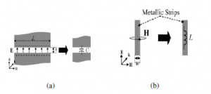
Figure 1: (a) Capacitance C is formed between the adjacent edges of two coplanar microstrips, (b) Inductance L associated with a metallic strip.
The first step in the design of a desired FSS cell using the proposed architecture above is to design the constituting resonators. The resonant frequency of the resonator can be determined by evaluating the effective inductance and capacitance of the unit cell. A first order approximation for the value of the capacitance is provided in [10].
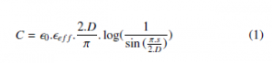
The capacitance value is determined by the cell length D, the gap width between the two adjacent strip s, and the effective dielectric constant of the supporting substrate. The inductance value, however, is only determined by the length and width of the metallic strip W and D [10].
In the design of this miniature FSS it is important to choose the constituent unit, the substrate and the existence or not of FSS multilayers. All these parameters control the FSS frequency response such as bandwidth, operating frequency, sensitivity to polarization and incidence angle.
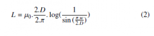
In this paper we propose an FSS unit cell with a stop-band filtering response at the resonance frequency of 5.9 GHz. It basically consists of a rectangular loop on the top side of RT5880 substrate with a relative permittivity of 2.2, dielectric loss tangent of 0.0009 and thickness of 0.127 mm. The unit cell has a dimension D and it is called periodicity. It has a size of compared to the wavelength at the operating frequency of 5.9 GHz. Parameter a represents the loop width and s is the gap between them. The whole cell geometry veries the symmetry propriety to the directions of polarization for horizontal and vertical polarized waves. This topology is illustrated in Figure 2 and Figure 3.
Figure 2: (a) FSS cell topology. (b) FSS cell on 3D.
2.1 Parametric study and simulations results
To synthesize the miniaturized FSS element, we initially assign its structural parameters according to the equations (1) and (2) in the CST studio as follows: D = 7 mm, a = 0.2 mm and s = 0.05 mm. A parametric study is done for periodicity value D, Loop width a and also for Gap between loops s in order to select the best configuration which gives more performances at 5.9 GHz resonant frequency. Transverse Electric (TE) mode is adopted in the parametric simulations. Based on results of reflection and transmission coefficients shown in Figure 4, it may be noted that, the FSS cell behaves as a pass-band filter. Furthermore, the variation of parameters D, a and s have significant effects on the resonant frequency. In fact, for transmittive performances with the increase of periodicity D, loop width a and the gap s, the resonance frequency is shifted from 5.9 GHz towards high frequency band. For reflective performance it can be seen that, the reflection zero value gets close to 0 dB with the increase of all parameters values. Clearly, the transmittive and reflective performances are dependent on the geometric parameters of the FSS cell.
In Table.1, the optimized geometric parameters values of the proposed FSS cell are given.
Table 1: Optimized geometric parameter of FSS cell at 5.9 GHz.
| Parameters | Value (mm) |
| Periodicity:D | 7.1 |
| Loop width:a | 0.1 |
| Gap:s | 0.1 |
As a recommendation in telecommunication systems, it is important that the FSS must be isotropic with respect to different polarizations and also insensitive to the incident angles of the electric field. In this case it is necessary that the transmission and reflection characteristics remain invariant when the polarization and the angle of incidence of the incoming wave change. To put in evidence these characteristics, and using the values of the optimized geometric parameters of the FSS cell, the transmission and reflection coefficients are evaluated for both TE and TM polarization modes and they are shown in Figure 4. Simulation results indicate that the FSS cell has a stop-band filter response with a reflective -10 dB bandwidth of 8.66 GHz at 5.9 GHz. An isotropic cell behavior is also observed because of identical values of transmission and reflection coefficients in the TE and TM modes. Thus, the proposed metamaterial cell structure enables the polarization independent operation.
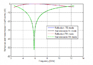
Figure 3: Transmission and reflection coefficients simulations for TE and TM modes at normal incidence.
The comportment of the cell under oblique incidence in TE and TM mode respectively, is calculated and depicted in Figures 5 and 6. From these results, we can see how the reflection zero changes when the incident angle increases over 45 ◦. In addition, it is observed that the FSS response is opposite for TE and TM modes according to the change of incidence angles. In fact, the amplitude levels of the reflection coefficient is failing with the increase of the incidence angle value in TM mode but it is more rapid in TE mode. This is because the surface impedance is proportional to the angle of incidence in TM mode whereas in TE mode it is the opposite [10]. It is to be noted that the proposed structure is isotropic and it has a stable performance for different incidence angles and polarizations.
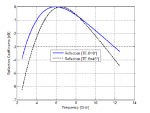
Figure 4: Refection characteristics for TE mode at different angle of incidence.
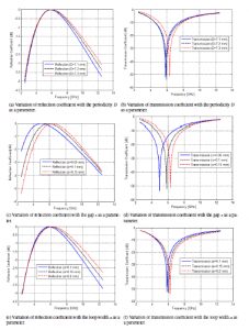
Figure 5: Simulated transmission and reflection coefficient value of proposed FSS unit cell.
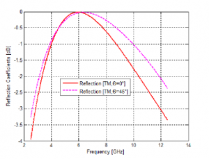
Figure 6: Refection characteristics for TM mode at different angle of incidence.
3. Integrated design of antenna and metamaterial filter
As is well known, the monopole antenna is widely used in V2V communications because of it’s omnidirectional radiation characteristics [18]. So, it has been chosen as the reference antenna. It is designed to operate at 5.9 GHz with a PEC circular reflecting ground plane. Large ground plane with Radius of 48 mm ( a distance of λ ) is taken to accommodate after, the integrated curved FSS. The length of the PEC wire L is 11.75 mm acting as a quarter-wave monopole and his radius (Rm) is taken 0.45 mm. This monopole is fed by a 50 Ω. The proposed antenna design is shown in Figure 7.
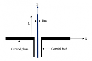
Figure 7: Cross-section view of the monopole antenna.
In order to verify the effect of the proposed FSS on bandstop filtering, an array of 9 × 42 unit cells as studied above is designed and then mapped on a cylindrical curved surface. The radius of the cylinder is chosen to keep the radial distance (Rc) between the antenna and the reflector around λ (near to 48 mm) with respect to the 5.9 GHz center frequency. This conformal FSS is then placed above the antenna ground plane. The monopole is laid on the center axis of the cylindrical FSS radome to keep axi-symmetry of the whole structure. The filter-antenna design is shown in Figures 8 and 9.
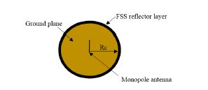
Figure 8: Top view of monopole with conformal FSS reflector.
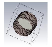
Figure 9: 3-D view of monopole with conformal FSS reflector.
Simulations of the composite design with and without cylindrical FSS are performed with CST-microwave studio in order to study the performance of the FSS filter when it is added to the antenna. The simulated reflection coefficient (S11) of the antenna with and without the conformal reflector are shown in Figure 10. It can be see from this figure, that the input reflection coefficient value changes significantly and was improved from -16.11 dB to -26.85 dB at 5.9
GHz. Furthermore, -10 dB bandwidth of the antenna decreases from
1.35 GHz to 239 MHz around the 5.9 GHz center frequency. So, it is much narrower which is very suitable for V2V communication in Dedicated Short Range Communication system (DSRC) frequency.
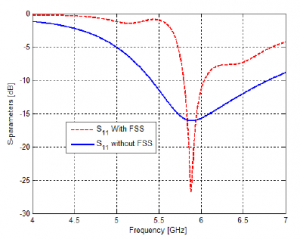
Figure 10: Simulated input reflection coefficient S11 of the antenna with and without curved FSS.
Radiation patrerns with φ=90 at 5.9 GHz of the monopole antenna and the corresponding FSS filter are shown in Figures 11 and
- From these patterns, omnidirectional radiation characteristics of the monopole antenna are kept. It is also clearly observed that with FSS, the antenna radiates more directivity. In fact, directivity was improved from 4 dBi to 5.54 dBi with the integration of the conformal FSS reflector. In addition, antenna gain increases from 4 dBi to reach 5.55 dBi with the FSS layer at 5.9 GHz. Total radiation efficiency of 95% of the antenna is also noted in the presence of the proposed cylindrical conformal FSS reflector layer. These results can be explained by the presence of constructive interferences of the phase component of radiated and reflected waves in the direction opposite to the FSS [19].
So, based on the above simulated results, one can deduce that the radiation characteristics of antenna were improved. The conformal FSS cylindrical layer can act as a RF filter which is directly added on to the antenna. It can be used in reducing interferences and shielding antenna especially in electromagnetic vehicular environment.
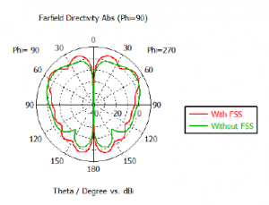
Figure 11: 2-D view of radiation pattern (directivity) of monopole antenna with/without FSS layer.
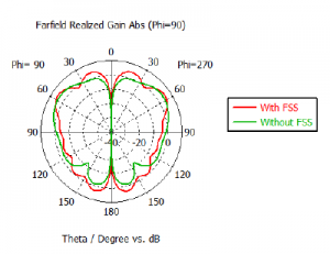
Figure 12: 2-D view of radiation pattern (gain) of monopole antenna with/without FSS layer.
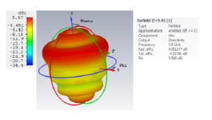
Figure 13: 3-D radiation pattern of monopole antenna with FSS reflector layer.
4. Conclusions
Due to the unreliable characteristics of the wireless medium, performance guarantees concerning the quality of the communication cannot be easily given. EMI in electromagnetic vehicular environments can disport the function of wireless devices. Therefore, the use of filter added on the antenna may be very beneficial to reduce the EMI effect. In this paper, a cylindrical conformal filter-antenna for V2V application is proposed. This design based on the cylindrical resonant FSS screen and placed at a small distance from the monopole element, enhances the radiation performance at 5.9 GHz. It provides an improvement in directivity by 1.55 dBi, in gain by 1.5 dB and also demonstrates also a narrow bandwidth which is mainly recommended for V2V communications. These results were successfully demonstrated by numerical simulations and in a future work by experimental prototypes. Moreover, due to it’s design simplicity and having only one layer, this filter should bear a low fabrication cost.
- Yang, Q.,Wang, H.,”Towards trustworthy vehicular social network,” IEEE Communication Magazine”, Vol. 53, No. 8, 42–47, 2015.
- Aisopoulos, P.,Kantartzis, N., Zygiridis, T.,Kosmanis, T., system ”emi charac- terization on automotive electronics,”, 2010.
- Groupe, L. W., and al., ”IEEE standard for wireless access in vehicular envi- ronments (wave)-multi-channel operation,” IEEE Std, 1609-4, 2016.
- Khairnar, V., D.,Kotecha, K.,”Performance of vehicle-to-vehicle communi- cation using ieee 802.11p in vehicular ad-hoc network environment,” arXiv preprint arXiv: 1304–3357, 2013.
- Rakhshan, A., ”The effect of interference in vehicular communications on safety factors,” arXiv preprintarXiv:1706.05758, 2017.
- Schmidt-Eisenlohr, F., ”Interference in vehicle-to-vehicle communication net- works”, feb. 9, 2010.
- Rybak, T., Steffka, M., ”Automotive electromagnetic compatibility (EMC),”
Springer Science and Business Media, 2004. - Chuang, C., T., Chung, S. J., ”New printed filtering antenna with selectiv- ity enhancement,”in 2009 European Microwave Conference (EuMC).IEEE, 747-750,2009.
- Bayatpur, F., Sarabandi, K., ”Multipole spatial filters using metamaterial based miniaturized element frequency selective surfaces,”IEEE Transactions on Mi- crowave Theory and Techniques, Vol. 56, No. 12, 2742-2747, 2008.
- Sarabandi, K., Behdad, N., ”A frequency selective surface with miniaturized elements, ”IEEE Transactions on Antennas and Propagation, Vol. 55, No. 5,
1239-1245, 2007. - Xue, J., Jiang, W., Gong, S, ”Wideband rcs reduction of microstrip array antenna based on absorptive frequency selective surface and microstrip res- onators,”International Journal of Antennas and Propagation, Vol. 2017, 2017.
- Lin, B., Du, S., Zhang, H., e, X., ”Design and simulation of frequency se- lective radome together with a monopole antenna,” Applied Computational Electromagnetics Society Journal, Vol. 25, No. 7, 620-625, 2010.
- Zhou, H., Qu, S., Li, B., Wang, J. Ma, H., Xu, Z., Peng, W., Bai, P., ”Filter- antenna consisting of conical fss radome and monopole antenna,”IEEE Trans- actions on Antennas and Propagation, Vol. 60, No. 6, 3040-3045, 2012.
- Chatterjee, S. K., Parui, A., ”Frequency dependent directive radiation of monopole dielectric resonator antenna using a conformal frequency selec- tive surface,”IEEE Transactions on Antennas and Propagation, vol. 65, no. 5, 2233-2239, 2017.
- Mondal, K., ”Bandwidth and gain enhancement of microstrip antenna by fre- quency selective surface for wlan, wimax applications,” Saadhana , Vol. 44, No. 11, 233, 2019.
- Bayatpur, F., Sarabandi, K., ”Single layer high order miniaturized element frequency selective surfaces,”IEEE Transactions on Microwave Theory and Techniques, Vol. 56, No. 4, 774-781, 2008.
- Munk, B. A.,” Frequency selective surfaces: theory and design”,John Wiley and Sons, 2005.
- Mishra, V.,Abegaonkar, M. P.,Kurra, L.,Koul, S. K.,”A configuration of fss and monopole patch antenna for bidirectional gain enhancement applications,” in 2018 IEEE Indian Conference on Antennas and Propogation (InCAP),IEEE, 1-4, 2018.
- Li, J.,Zeng, Q., Liu, R., Denidni, T. A.,”A gain enhancement and flexible con- trol of beam numbers antenna based on frequency selective surfaces,” IEEE
Access,Vol. 6, 6082-6091, 2018.