Mutual Reduction in the Coupling of the MIMO Antenna Network Applied to the Broadband Transmission

Adv. Sci. Technol. Eng. Syst. J. 5(2), 338–343 (2020);
 DOI: 10.25046/aj050244
In this article, a new form of UWB (ultra-wide-band) antenna operating to the desired specifications, obtained from a base antenna to which some modifications are made. The proximity of the antennas causes a mutual coupling phenomenon thus generating an apparent modification of their characteristics. It is therefore crucial to have the minimum level of insulation with a small possible separation distance between the antennas to ensure efficient operation of our multiple input and multiple output (MIMO) system. The separation spacing between the antennas is close to 0.15λ0 (λ0 is the wavelength in free space), where the coupling can be very weak. To overcome this weakness, two efficient methods are applied to minimize mutual coupling in a four-element MIMO antenna, such as the use of the neutralization line and the use of split ring resonator metamaterial (SRR). The objective of our paper is, on the one hand the design of UWB antenna, and on the other hand to minimize the coupling between four UWB-MIMO antennas using the two methods of isolation mentioned above. A coupling minimization of more than 15 dB is obtained using the neutralization line and more than 20 dB with the use of metamaterial while maintaining the operating band and radiation specifications of the MIMO antennas.
1. Introduction
In recent years and today, the MIMO antenna has demonstrated its ability to improve the efficiency and capacity of the satellite communication system [1]. Despite the advantages of the MIMO antenna in modern technology, mutual coupling is a delicate challenge, given the small distance between the elements [2,3]. The effects of the interaction between all components of the MIMO antenna array have the effect of reducing the operation of the system by increasing the correlation coefficient and the channel loss. This reduces the antenna gain and distortion of the antenna pattern. Radiation [3-5], and consequently reduces the efficiency of the MIMO antenna. The influence of the near fields performed by the neighboring antenna with the presence of the surface waves has a great influence on the radiating elements in the emission-reception system and more precisely on the coupling between antennas [1,6]. In cases where the antennas are placed on dielectric substrates with low permittivity [3], the fields of the antennas are very close, a very strong coupling these produce. The problems related to antenna linkages have increased since the end of the 20th century. Many research studies have been conducted and are continuing to improve the characteristic radiation efficiency of antennas. Metamaterial are a promising research topic in various fields, in particular electromagnetism [7], whether for circuit applications (filters, phase shifters, etc.) or for radiation applications (antennas, diffraction, stealth). These are elaborate materials, consisting of periodic elements of small size (relative to the wavelength) and providing, in specific frequency bands, particular properties different from those of natural materials [8,9]. Potential benefits of these structures include, for example, miniaturization of antennas, expansion of their bandwidth or reduction of inter-element coupling within a network. To take into account the constraints inherent in the need for discretion and to respond to the current trend of low thickness solutions, we favored a planar technology for the design of this new antennal solution. The delicate compromise between bandwidth, dimensions and electrical performance leads us to propose a new radiating print. In this article, we propose a very wide bandwidth rectangular patch antenna on a FR4 substrat, with insertion of the notches at the ground plane and shape modifications for the radiating element. Compared with conventional microstrip antennas, the bandwidth is around 15 GHz for a reflection coefficient of -10 dB. A physical structure is proposed to minimize the mutual coupling between the elements constituting the MIMO system with four patches very close to each other. Two isolation techniques are studied and compared in this article. Starting with the use of an isolation technique called DGS (Defected Ground Structure) is to introduce changes to the structure of the ground plane to change the current distribution. In MIMO systems, the effect of the notch filter is applied in order to reduce the mutual coupling between the radiating antennas. The application of the DGS method is to introduce slits on the ground plane [10-12] The DGS solution is very easy to implement since its operation depends on the resonance frequency rather than the types of antennas, so a combination of this technique with the technique called “neutralization technique” (NL) used to decouple the two UWB antennas. MIMO placed side by side and involves inserting a line between the elements in a well-defined position or short-circuit when the antenna are positioned very closely on a small mass plane. Noting that the electromagnetic coupling presented between two patchesnearby is mainly of the capacitive type [12,13]. Indeed, by introducing an inductance between the two patches, a rejection filter behavior allows decoupling [14,15]. A decoupling of the order of 14 dB is obtained in the operating band [3.2 – 17.7] GHz. The second solution is to use a structure based on metal rings (Split Ring Resonators or SRR) with a permeability of negative value. Four SRRs in series are located along the distance between two adjacent antennas and two opposite antennas forming the symbol (+) based on the upper layer of the FR4 substrate to separate the antennas from each other to ensure good isolation. Mutual coupling between the elements of the MIMO antenna systems can be greatly reduced, with isolation greater than 10 dB over the majority of the antennas operating band. In this paper, the design of UWB antenna is presented. The coupling between four UWB-MIMO antennas using the two methods of isolation (NL and metamaterial) is minimized. The gain of isolation betwen antennas more than 15 dB using the neutralization line and more than 20 dB with the use of metamaterial are obtained while maintaining the operating band and radiation specifications of the MIMO antennas.
2. Antenna characterization
We start at the beginning of our design with a square-shaped printed antenna powered by microstrip line. The choice of the power line is based on the fact that this line must have a characteristic impedance of 50 ohms, adapted over a very wide frequency band. The geometry of this antenna consists of a rectangular patch printed on the top face of a FR4 type substrate. The ground plane is a partial plane printed on the bottom surface of the substrate. The reflection coefficient modulus of the initial antenna is greater than -10 dB for frequencies in the band [3 – 11] GHz. But in the band [11 – 16.7] GHz the modulus of reflection is less than -10 dB (see figure 1 curve a). This antenna is therefore not well suited over the entire frequency band studied (X, Ku and Ka bands). According to the influence of the modifications made on the base antenna, and in order to improve its characteristics and mainly its adaptation as well as obtaining an ultra-wide band operation The design is made by introducing some modifications on the structure of the base antenna, in particular on the shape of the radiating element and by adding slots on the patch and on the ground plane; we present in this part our complete antenna with all the modifications made. Figure 2 presents the geometric shape as well as the dimensions of our antenna presented. The different characteristics of the antenna will be presented and commented. Figure 1 presents the geometry as well as the dimensions of the proposed antenna printed on a substrate FR4 of relative permittivity εr = 4.4, loss tangent tan = 0.02 and thickness equal to 1.6 mm. The parameters associated with the structure of the antenna studied are shown in Table 1.
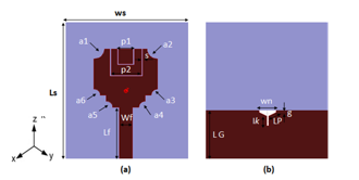 Figure 1: Structure of the patch antenna studied: (a) In front view (b) bottom view.
Table 1: Geometric parameters of the studied antenna.
| Parameters | Values (mm) | Parameters | Values (mm) |
WS |
25.52 | LS | 31 |
WPa |
14.52 | LPa | 14.52 |
WF |
2.85 | LF | 13.52 |
LG |
12.62 | HSu | 1.6 |
a1 |
1.45 | g | 0.36 |
a2 |
1.5 | l1 | 7.5 |
a3 |
1.1 | Lp | 1.62 |
a4 |
1.1 | wn | 3.1 |
a5 |
1.1 | Lk | 0.75 |
a6 |
1.1 | Lp | 2.35 |
p1 |
10 | ||
p2 |
4 |
This antenna has a reflection coefficient of -10 dB over the entire frequency band [3.1 – 16.8] GHz (Figure 2 curve b).
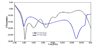 Figure 2: Reflexion coefficient S11 of the UWB antenna: (a) Initial design, (b) Final design.
The influence of modification is clearly visible in the improvement of the adaptation.
3. NL Decoupling structure design
At the beginning a research was done to show the effect of the neutralization line on the general radiating element and more precisely on the insulation between the elements that constituted our system. The basic idea of this method was to compensate for the complex electromagnetic coupling existing between the neighboring antennas by opposite coupling reaction. As the coupling between the antennas is capacitive, the line mainly makes it possible to provide a reaction or an inductive effect to oppose the capacitive effect of the coupling between antennas [16]. This technique has been used to guarantee improved isolation of several multi-antenna systems [17]. Moreover, the neutralization line supports strong currents so that the direction of current is directed towards the antenna itself to radiate and not towards the power port of the second antenna. In addition, it is possible to cancel the coupling of all the paths [16]. Then this method is the one selected to improve the isolation of the four patch antennas of our multi-antenna system. The insertion of the line is done in the area where the amplitude of the currents is the highest, which corresponds to the zones of low impedances. A simple four-element structure has been used. The width and length of the microstrip antenna are the same. The separation distance between the four elements is 0.15λ0. The MIMO antenna structure is based on a FR4 type substrate 60 x 48 mm in size with a permittivity (εr) of 4.4 mm and a thickness of 1.6 mm. The proposed antenna scheme is shown in figure 3. NL was placed between items like shown in Figure 4.
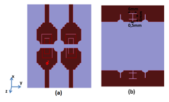 Figure 3: MIMO studied with four elements without NL.
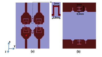 Figure 4: MIMO studied with four elements: with NL
3.1. Reflexion coefficient (Sii) Analysis
Several simulations have been carried out to find the optimal position of the neutralization line to maintain the bandwidth in adaptation. The simulation result has shown a small assignment on the parameters S11, S22, S33 and S44, which are in coincidence. The scattering parameters simulated are shown in figure 5. By comparing the two simulation results without and with NL, it is noted that the parameters of the Sii reflection coefficients (S11, S22, S33 and S44 are the same because of the symmetry of the structure) are not strongly modified, the MIMO antenna covered a very wide bandwidth of – 10 dB.
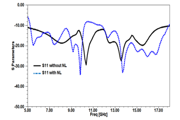 Figure 5: Reflexion coefficient S11 of the UWB antenna without and with NL
3.2. Isolation Parameters Analysis
The transmission parameters Sij from antenna j to antenna i (S21, S31 and S41) reveal and show that the adjacent antennas are strongly coupled with a decoupling method that is easy to design and execute compared to that presented in several articles. The parameter level is decreased for our current MIMO system. According to the results obtained by simulation, it has been found that the influence of an NL makes it possible to find an acceptable decoupling level for a network of four antennas. This helps us to create a model similar to the one created by simulation. Compared to the MIMO-UWB antenna without NL application, our studied MIMO antenna not only preserves the overall performance for each element, but also further minimizes the coupling of 21 dB at 15 GHz and 15 dB at 8 GHz and presents an isolation more than 15 dB, (see figures 6, 7 and 8).
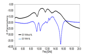 Figure 6: Parameters S21 simulated of MIMO antennas (adjacent) without and with NL
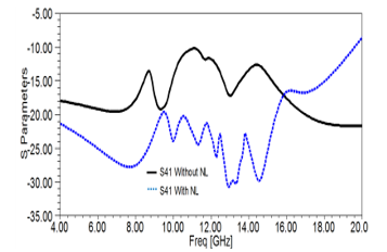 Figure 7: Parameters S41 simulated of MIMO antennas (opposite) without and with NL
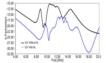 Figure 8: Parameters S31 simulated of MIMO aantennas (symmetrical) without and with NL
4. Structure and decoupling of metamaterials
Research has been carried out to ensure and obtain an electromagnetic mulberry allows to isolate the flux and the interference to the radiation of proximity of adjacent antennas. Subsequently, a proposed method based on the application of the metamaterial was presented which makes it possible to minimize the coupling levels [17]. So at the beginning a design of a SRR presented to ensure the operation around the band of frequencies mentioned initially and are suitable the impact on the resonance of the components of the MIMO antenna. The applied SRR unit cell has been dimensioned for band operation. The substrate used for the simulation is the FR4 which has a relative permittivity of 4.4, tangential losses of the order of 0.002 and a thickness of 1.6 mm. The external side of the square is equal to 2.4 mm. The width of the track in copper is 0.3 mm. The width of the cut of the rings is 0.34 mm (figure 9).
With the aim of guaranteeing isolation over our entire frequency band, we are doing a study on the size of the SRR aperture in order to see the influence of this variation on the resonance frequency of SRR. According to the simulation results mentioned in the figure 10 and figure 11, we notice well that we have a relationship of proportionality between the increasing of the opening for the two rings of our SRR and the resonant frequency that evolves with the opening.
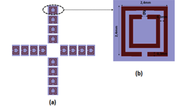 Figure 9: Geometric of studded split ring resonators: (a) 4×4 unit cells in front view and (b) Unit cell
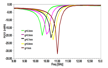 Figure 10: Parameter of S22 for several aperture values in the SRR
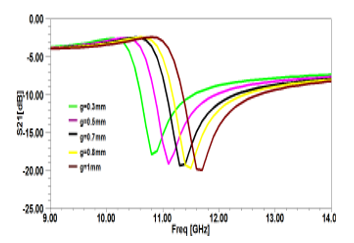 Figure 11: S21 parameters for several aperture values in the SRR
The structures are placed between the antennas at an optimized separation distance at 0.15λ0 and are composed of 4 groups of SRRs over the substrate. Each group has four integrated SRR units between the antennas for good isolation between the antenna elements. This configuration is illustrated in Figure 12. In this part, we are going to study the influence of an SRR cell network between the two adjacent antennas. We have looked for presenting an electromagnetic blackberry in order to isolate radiation fluxes and interferences from the proximity of adjacent antennas. So a proposed solution based on the use of the metamaterial has been presented which allows stopping or minimizing the propagation of surface waves, thus reducing the mutual coupling in a MIMO antenna.
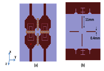 Figure 12: UWB MIMO antenna associated with SRR cells in front view and bottom view.
4.1. Reflexion coefficient (S11) Analysis
We note that the simulated structure has a stability of the S11 reflection coefficients of four MIMO antennas with SRRs over the entire desired band. Figure 13 indicates the parameters S11 of the proposed antenna. The influence of the material is clearly visible in the improvement of the adaptation of the antenna. We can conclude that the structure with the application of the SRR contributed to the increase of the MIMO antenna performance in terms of reflection coefficient and consequently allowed us to obtain a better ULB structure.
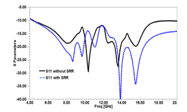 Figure 13: Reflexion coefficient S11 of the UWB antenna with SRR.
4.2. Isolation Parameters ( Analysis
Inter-element electromagnetic coupling presents a difficulty between the components during start-up. Here, a chain of separation between the elements is an assembly of two periodic networks consisting of metallic line and a resonator network makes it possible to have a negative permeability whereas the line network is characterized by a negative permittivity. The assembly of these two networks contributes to having a negative permittivity and permeability at the same time. The SRR chain at the highest point of the substrate was used to ensure isolation improvement. As previously reported, the mutual coupling is more important in the case where the radiating elements are very close. For this reason, we are interested in this approach to the analysis of the mutual coupling between each two adjacent, opposite and symmetrical antennas. In fact, as shown in figures 14, 15 and 16, the initial mutual coupling measured in terms of transmission coefficient at the frequency of 10.7 GHz was -7.2 dB, -10.1 dB and -11.6 dB between antenna 1 and 2, 1 and 3, 1 and 4 respectively. After the use of SRR, the isolation becomes more improved to obtain the value of -24.3 dB, -22.2 dB and -27.6 dB between antenna 1 and 2, 1 and 3, 1 and 4 respectively. Thus, the condition of having a mutual coupling lower than -17 dB imposed to maintain the performance of a MIMO system.
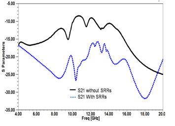 Figure 14: Parameters S21 simulated of MIMO antennas (adjacent) without and with metamaterial.
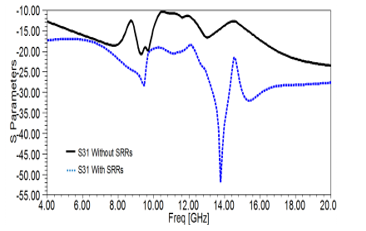 Figure 15: Parameters S31 simulated of MIMO antennas (symmetrical) without and with metamaterial.
The observation on the figures 14, 15 and 16 showing the transmission coefficients indicates better quality with reduced power losses across the desired band. An isolation protection gain of more than 10 dB over the entire band is achieved. This is explained by the isolation performance between the antennas with this predicted structure. This separation between the antennas ensuring the efficiency of the transmission system constituting our space links.
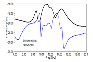 Figure. 16: Parameters S41 simulated of MIMO antennas (opposite) without and with metamaterial.
5. Conclusion
In this article, we presented a new structure of a MIMO antenna array that belongs to the UWB ultra-wideband UWB antennas categories. We presented several approaches to improve the performance of MIMO systems. The simulation relating to a MIMO antenna has been completely described, have shown great efficiency for the improvement of the isolation of a system consisting of four UWB antennas originally presented. The results of electromagnetic simulation have shown the gain provided by these techniques for increasing the isolation between antennas in the band of interest. A solution that seems to be relevant is obtained using the neutralization line technique. For this solution, the insulation in the UWB band is greater than 18 dB. Another solution made it possible to highlight the role of the split-ring resonator, in the design of UWB microband antennas with the insertion of periodic SRR structures. We were able to increase the isolation without losing the UWB characteristics. These results show that the proposed structures contribute to meeting the requirements of modern communication systems dedicated to 5G.
- M. A. Vázquez, et al, “Precoding in multibeam satellite communications: Present and future challenges,” IEEE Wireless Commun., vol. 23, no. 6, pp. 88–95, Dec. 2016.
- B. H. G. Gao, L. He, S. Wang, and C. Yang, “Investigation of A Reconfigurable Dual Notched UWB Antenna by Conceptual Circuit Model and Time-Domain Characteristics,” Microwave and Optical Technology Letters, vol. 59, pp. 1326– 1332, 2017.
- A. Iqbal, O. A. Saraereh, A. W. and S. Bashir, “Mutual Coupling Reduction Using F-Shaped Stubs in UWB-MIMO Antenna”, IEEE Access vol. 6, pp. 2755–2759, 2018.
- I. Szini, A. Tatomirescu, and G. F. Pedersen, “On Small Terminal MIMO Antennas, Harmonizing Characteristic Modeswith Ground Plane Geometry,” IEEE Antenna Propag. Trans. On, vol. 63, no. 4, pp. 1487 – 1497, 2015.
- B. H. G. Gao, L. He, S. Wang, and C. Yang, “Investigation of A Reconfigurable Dual Notched UWB Antenna by Conceptual Circuit Model and Time-Domain Characteristics,” Microwave and Optical Technology Letters, vol. 59, pp. 1326–1332, 2017.
- L. Malviya, R. K. Panigrahi and M. V. Kartikeyan., “A 2×2 Dual-Band MIMO Antenna with Polarization Diversity for Wireless Applications,” Progress In Electromagnetics Research C, vol. 61, pp. 91-103, 2016.
- A. Dadgarpour, M. S. Sorkherizi and A. A. Kishk, “Wideband, Low loss Magneto Electronic Dipole Antenna for 5G Wireless Network with Gain Enhancement Using Meta Lens and Gap Waveguide Technology Feeding,” IEEE Transactions on Antennas and Propagation, vol. 64, no. 12, pp. 5094 – 5101, 2016.
- M. S. Sharawi, S.K. Podilchak, M. T. Hussain and Y. M. M. Antar, “Dielectric Resonator Based MIMO Antenna System Enabling Millimeter-Wave Mobile Devices,” IET Microwaves, Antennas& Propagation, vol. 11, no. 2, pp. 287 – 293, Jan. 2017.
- G. K. S. Pandey, H. S. Bharti, P. K. Meshram, M. Kumar, “Design and Analysis of Ψ-Shaped UWB Antenna with Dual Band Notched Characteristics,” Wireless Personal Communications, vol. 89, pp. 79-92, 2016.
- R. B. Rani and S. K. Pandey, “A CPW-Fed Circular Patch Antenna Inspired by Reduced Ground Plane and CSRR Slot for Uwb Applications with Notch Band,” Microwave and Optical Technology Letters, vol. 59, issue 4, pp. 745-749, 2017.
- G. K. Pandey, H. S. Singh, P. K. Bharti and M. K. Meshram, “Design and Analysis of Multiband Notched Pitcher-Shaped UWB Antenna” International Journal of RF and Microwave Computer-Aided Engineering ,vol. 25, pp. 795–806, 2015.
- A. P. Singh, R. Khanna, and H. Singh, “UWB Antenna With Dual Notched Band For WIMAX and WLAN Applications,” Microwave and Optical Technology Letters vol. 59, pp. 792– 797, 2017.
- T. Jiang, T. Jiao, and Y. Li, “Array mutual coupling reduction using L-loading e-shaped electromagnetic band gap structures,” International Journal of Antennas and Propagation, vol. 2016, Article ID 6731014.
- S. Zhang and G. Pedersen, “Mutual coupling reduction for UWB MIMO antennas with a wideband neutralization line,” IEEE Antennas and Wireless Propagation Letters, vol. 15, pp. 166-169, 2016.
- C. Abdelhamid, M. Daghari, H. Sakli and C. Hamrouni, ”A New UWB-MIMO Multi-Antennas With High Isolation For Satellite Communications,” 15th International Wireless Communications & Mobile Computing Conference (IWCMC), Maroc, pp. 152-155, 24-28 Jun 2019. (978-1-5386-7747-6/19/$31.00 ©2019 IEEE).
- T. Jiang, T. Jiao, Y. Li, and W. Yu, “A low mutual coupling MIMO antenna using periodic multilayered electromagnetic band gap structures,” Applied Computational Electromagnetics Society Journal, vol. 33, no. 3, pp. 305-311, 2018.
- K. Wei, J. Li, L. Wang, Z. Xing, and R. Xu, “Mutual coupling reduction by novel fractal defected ground structure band gap filter,” IEEE Transactions on Antennas and Propagation, vol. 64, pp. 4328-4335, 2016.
No related articles were found.