Electronic Steering of the Vehicle Axle with Force Feedback

Adv. Sci. Technol. Eng. Syst. J. 5(2), 280–286 (2020);
 DOI: 10.25046/aj050236
The technology of electronic steering with force feedback is related to electronic vehicle control. This technology is also known as “steer-by-wire” technology and is specific in that there is not any mechanical connection between the axle and the steering wheel. This technology is currently not very widespread. However, developments in the automotive industry are slowly moving towards this technology in the context of autonomous vehicles. This study includes a review of current technologies in this area and suggests a technical solution for Steer-by-Wire technology and its verification in the real vehicle model in the university environment.
1. Introduction
The paper follows the work that was presented at the International Carpathian Control Conference (ICCC) [1]. This work dealt with the design of the electronic steering wheel and will be briefly described in this article as well. This article is further expanded by research about Steer-by-Wire technology and axle control using linear servos and a designed electronic control system. The main goal of this work is to make some progress in the area of Steer-by-Wire technology.
The technology of Steer-by-Wire is currently very widespread not only in the automotive industry. It is most often mentioned in connection with autonomous vehicles. It is a very special technology which must meet rules for safe and reliable operation. To ensure the safety of drivers and all road users, vehicles equipped with these systems must contain many electronics and sensors. However, the development of these technologies is still underway, and it will take some time to fully deploy to normal traffic.
In modern vehicles, systems that interfere with vehicle control are already implemented. However, we cannot call them autonomous. An example of such a system is a parking assistant, adaptive cruise control or a system that holds the vehicle in the traffic lane.
Electronic vehicle control technology can be solved in many ways. It depends only on our requirements. As a first requirement, we can consider the independent steering or steering of both wheels simultaneously. Yamaguchi and Murakami [2] described a standard Steer-by-Wire model with one steering motor, which controls both wheels together via rack and pinion. It is based on a classic electric power steering system without a mechanical connection with a steering wheel. An example of a driving assistant system is described by Liu et al. [3] and it is based on the same principle. As another requirement can be considered the physical principle of the selected actuators. Ye et al. [4] explain the model of the vehicle’s electro-hydraulic system that controls the steering of all four wheels.
Other issues in this area can provide feedback to the driver according to the road surface or advanced methods of control. The solution may be to implement force, torque and yaw rate sensors or accelerometers as described in [5-7]. A very interesting solution is also described by Fahami et al. [8]. They propose an algorithm to create force feedback torque based on the current measurement of the DC motor.
For advanced methods of control, a bilateral control scheme to improve vehicle handling can be mentioned, which was proposed by Zheng et. al. [9].
The main content of this paper is about the proposal of an electronic steering system technical solution, which is based on a clear electric principle. This choice depends on a lower price than electrohydraulic systems. It utilizes independent steering of both front wheels with the use of power linear servos mounted on each wheel.
Figure 1 shows the block diagram of the chosen technology. It consists of a steering wheel unit, steering control system and two independent linear actuators. The steering wheel unit is designed for generating force feedback and setting the desired steering angle and the steering control system serves for controlling linear servos according to the desired steering angle set by a driver.
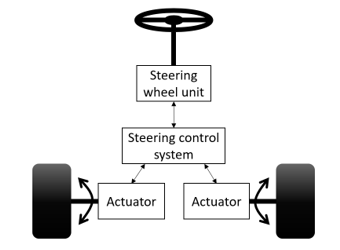 Figure 1 – Block structure of the proposed system
2. Design of steering wheel unit
In the beginning, the model of the steering wheel unit was designed. There are more options to create a steering wheel unit to control the steering and generate force feedback to the driver. In [2] the steering wheel rotation is proposed utilizing a motor and a belt drive. This method of torque transmission was also chosen in this work for easier implementation. The disadvantage of the gears is the play between the teeth, which in this case could cause steering insensitivity.
The main task of the proposed system is to provide the steering wheel position to the steering control system and generate force feedback to the driver. Force feedback is generated by a DC motor. The DC motor shaft is coupled to the steering wheel via a dual belt drive, which increases the final torque of the steering wheel.
The angle of the steering wheel is measured using the SEAT automotive position sensor. The advantage of this sensor is that it provides data over the CAN bus and it is also very reliable due to its robust design.
The Arduino UNO board was selected as the main control unit and it was interfaced with the CAN bus shield based on MCP2515 chip. The power of the DC motor is controlled by the dual H-bridge according to the PWM signal in the range of 0-5 V from the Arduino unit. Part of the design is also a current sensor. It measures the direction and value of the DC motor current. The current direction is important to determine if the driver affects the steering wheel with any force.
Figure 2 shows the whole structure of the steering wheel unit with the possibility of setting parameters through a computer application. As can be seen from the picture, the structure is divided into three levels according to their main task.
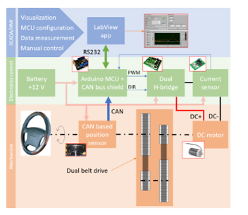 Figure 2 – Block diagram of the steering wheel unit
2.1. Construction design and assembly
As the feedback motor, the DOGA 162 was chosen. It is a motor that uses permanent magnets to generate a magnetic field. The principle is based on the mutual attraction of the positive and negative poles [10]. The initial torque of the chosen motor is about 1 Nm from the datasheet. Parameters like performance, size, weight, availability, and price played a major role in the choice of this DC motor.
As already mentioned, the power transfer of the feedback motor to the steering wheel shaft was designed by a dual belt drive. The belt drive was designed to meet the requirement for the resulting torque. First, the gear ratio was defined as the same for both gears as 4.5. HTD pulleys with the required number of teeth were then selected based on the gear ratio. The total gear ratio through both gears was calculated as 20.25. Then it was necessary to calculate the minimal axial distance between pulleys. The actual axial distance was then selected based on the standard lengths of the Continental HTD belts.
The equations and formulas for obtaining the belt length are described in [1].
The calculation of the resulting starting torque of the DC motor is also described in [1].
Finally, the initial torque from the total gear ratio has been calculated and it can be noted that its value meets the specified requirement of 20 Nm. This value can be considered as enough for this application.
In Figure 3, the mechanical construction of the model is shown. The prototype frame is made of metal sheets and threaded rods. All shafts were mounted with the construction frame through ball bearings fixed in bearing holders. The position sensor was connected to the steering wheel shaft using a 3D printed connecting part.
 Figure 3 – Realized mechanism of the steering wheel unit
2.2. Electronics control system
The design of the electronic control system includes the selection of suitable components and their correct connection for safe operation.
Figure 4 describes a regulation loop showing which components represent the controller, the system and the measured feedback.
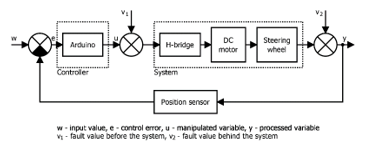 Figure 4 – The regulation loop of the electronic steering wheel unit
The controller is the evaluation board Arduino UNO. The manipulated variable is generated by the PWM signal in the 0-5 V range. The system consists of a dual H-bridge, DC motor, dual belt drive, and steering wheel. The dual H-bridge controls the power of the DC motor based on the manipulated variable. The steering wheel position reference value can be considered as an input. The actual controlled position can be considered as the output. The position feedback is measured by the already mentioned sensor based on CAN.
The CAN bus is a communication standard used for data transfer in the automotive industry. A twisted-pair copper line is usually used as the transmission medium [12].
The position sensor provides data about the current position and speed of rotation. The sensor resolution is 240 values per revolution. Measurement of its ranges was performed using the PCAN-USB interface from Peak System.
The Arduino unit was developed as an open-source platform. For programming, it is possible to use the development environment Arduino, which is free. The main function of this unit is to measure and control the position of the steering wheel. For this purpose, the PID control algorithm was implemented in the Arduino. Another function is cyclical data sending via a serial interface to a computer application. In addition to sending data, the unit can also receive data in the form of configuration commands from the application.
The mentioned application was developed in LabView from National Instruments. This environment uses a block structure for programming. The final design is shown in Figure 5.
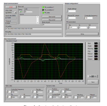 Figure 5 – Steering wheel unit application
The application was designed and divided into three sections. The first section consists of serial communication settings, error indicators and the display of received and sent buffers to or from the Arduino unit.
The second section is for model configuration and manual control. There is the possibility of manually adjusting the steering wheel angle as an offset position or DC motor power in the 0-255 PWM range to measure step response. This section also contains a form for setting PID controller parameters and controller frequency.
The last section includes tools for data measurement and visualization. Except for the graph, which shows the last values on the selected timeline, this section also contains numeric indicators of current values. Measured data can be saved to TDMS file using the save button.
2.3. System identification and controller design
An important part of the work is to determine the parameters of the proposed model. Deterministic methods based on measured step response were chosen for system identification. For step response measurement, the developed application was used. That was measured during the steering wheel rotation of 360 degrees. The step size was set to match the maximum motor power. According to the step response, it was found out that it is the integration system. It will not stabilize.
The inertia integration system can be described by the following form of the transfer function [13]:
![]() Integral time and inertia were obtained using standard identification methods. The calculations revealed that it is a first-order system defined by the following form of the transfer function [13]:
Integral time and inertia were obtained using standard identification methods. The calculations revealed that it is a first-order system defined by the following form of the transfer function [13]:
 Subsequently, a step response was simulated using a calculated transfer function in Matlab Simulink. The accuracy of the simulated step response was verified by comparison with the measured step response. Figure 6 shows that the transfer function parameters have been calculated correctly.
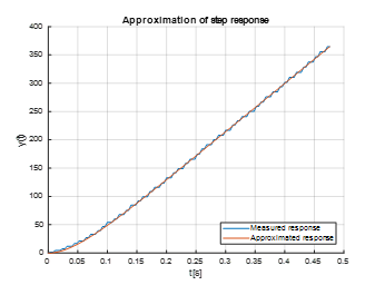 Figure 6 – Step response approximation
The controller parameters were then calculated for the derived transfer function. The Desired model method was used for this purpose. This method established a PD controller for the first-order integration system.
The following equation shows the transfer function of a conventional PD controller in the discrete form [14]:
![]() Where:
Where:
kp – proportional gain,
TD – derivative time
T – controller sample time
The controller parameters were obtained for 0 % overshoot and 100 Hz sampling frequency. The calculation of the parameters is given by the following formulas [14]:
 Where:
T1 – transfer function time constant,
k1 – transfer function coefficient,
T – sample rate
α – table coefficient
Figure 7 shows the process of control with proposed parameters while turning the steering wheel. To facilitate steering wheel rotation, the manipulated variable was limited to 20% of DC motor power.
 Figure 7 – Final process of control
The graph also contains the measurement of feedback motor load using the current sensor based on ACS758. Due to high noise, the signal was adjusted using an exponential filter.
The exponential filter is described by equation below [15]:
 Where:
yF(i) – new filtered value,
KF – filtration coefficient,
yM(i) – measured value,
yF(i-1) – previous filtered value
The value of the filtration coefficient was chosen as 0.03.
Figure 8 shows the different methods of current signal conditioning. There is a comparison of moving average and exponential filtration.
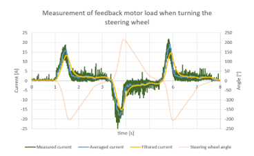 Figure 8 – Feedback motor load while turning the steering wheel
The solution for the future implementation of other systems such as parking assistance or vehicle stabilization can be designed advanced control with dynamic change of controller parameters depending on the required power of the motor.
In Figure 9, the prototype model of the electronic steering wheel is shown.
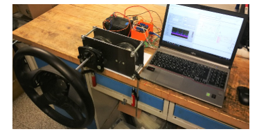 Figure 9 – Electronic steering wheel unit prototype model
3. Design of the steering control system
In the design of the steering control system, it was necessary to select appropriate components such as actuators or control unit. As the actuators, the super duty linear servos were selected for the wheel steering. These actuators were selected according to the calculated parameters described in [16]. This linear actuator can exert a force greater than 2 kN and includes a 10 kΩ potentiometer to provide information about the current position. For the control of linear drives, the cRIO from National Instruments together with Roboclaw motor driver was chosen.
The same procedure as for the steering wheel unit was performed to determine the PID controller parameters. This means that experimental identification was performed first. Then the controller parameters were derived for the determined transfer function [16].
 Figure 10 – Structure of the proposed electronic steering system, [16]
Figure 10 shows the whole structure of the proposed steering control system with selected components.
Figure 11 shows the linear actuators mounted on the axles of the test vehicle.
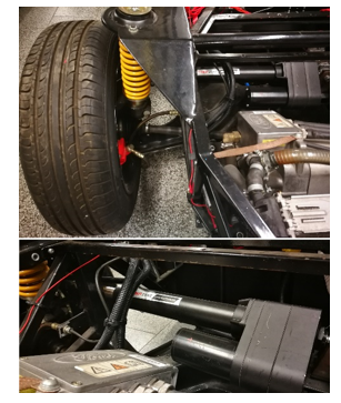 Figure 11 – Picture of testing vehicle with steer-by-wire technology
Finally, the program of the control system was created in LabView. The cRIO was not only used for testing, but also as a main unit of the steering control system. The control system also implements the condition of Ackermann steering geometry. The calculation of the Ackermann formula is described in [16].
Ackermann steering geometry is based on the different steering angles of the inner and outer wheels when the vehicle turns. The aim is that the turn radius of both wheels ideally has a common midpoint. As a result, the tires are not so stressed when cornering the vehicle. The principle and more detailed information are described by Zhao et al. [17]. They deal with the design of the steering mechanism based on Ackermann.
4. Results and future work
This chapter summarizes the results of this work During this work, two systems were developed which communicate with each other. The first is the steering wheel unit, which is used to set the desired position of wheels and generate force feedback back to the driver. The maximum torque of the feedback DC motor was calculated as 20 Nm. The second system controls the linear actuators of both wheels.
Figure 12 shows the final relation between the steering angle of both wheels and the steering wheel position. The difference between wheels is given by Ackermann steering geometry of our car.
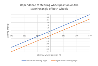 Figure 12 – Relationship between steering angle and steering wheel position
The goal of further development is to find a solution for road surface feedback and get it to the driver through the steering wheel. The solution can be force or torque sensors in combination with accelerometers or yaw rate sensors mounted on the wheels of the vehicle as described in [18, 19].
5. Conclusion
The current automotive world is moving towards autonomy and the replacement of mechanical systems by electronic ones. Therefore, this work was focused on the design and implementation of electronic vehicle control without a mechanical connection between the axle and the steering wheel. In this work were developed and implemented two systems that can communicate with each other. The first system is the steering wheel unit and the second is the steering control system. The steering wheel unit represents a steering wheel coupled to a DC motor using a dual belt drive and the position is measured by CAN based sensor. The main role of this system is to transmit the requirement for the steering angle of the wheels in the form of an analog signal to the steering control system. The other role is to generate force feedback back to the driver by the steering wheel. The steering control system is represented by the control unit, motor controller and two linear actuators for turning the wheels.
The result of this work is the possibility of independent control of both wheels according to the steering wheel position. The advantage of independent control is software geometry adjustment. The proposed system was tested on the real model of the electric car at the university.
Conflict of Interest
The authors declare no conflict of interest.
Acknowledgment
This work was supported by the European Regional Development Fund in the Research Centre of Advanced Mechatronic Systems project, CZ.02.1.01/0.0/0.0/16_019/0000867 within the Operational Programme Research, Development and Education and the project SP2020/57 Research and Development of Advanced Methods in the Area of Machines and Process Control supported by the Ministry of Education, Youth and Sports.
- T. Pawlenka and J. Škuta, “Electronic Steering With Force Feedback,” 2019 20th International Carpathian Control Conference (ICCC), Krakow-Wieliczka, Poland, 2019, pp. 1-5. doi: 10.1109/CarpathianCC.2019.8765925
- Y. Yamaguchi and T. Murakami, “Adaptive Control for Virtual Steering Characteristics on Electric Vehicle Using Steer-by-Wire System”, IEEE Transactions on Industrial Electronics, vol. 56, no. 5, pp. 1585-1594, 2009. Available: 10.1109/tie.2008.2010171.
- X. Liu et al., “Driving Assist System for Ultra-Compact EVs-Fundamental Consideration of Muscle Burden Owing to Differences in the Drivers’ Physiques”, Actuators, vol. 7, no. 3, p. 44, 2018. Available: 10.3390/act7030044.
- M. Ye, Q. Wang and S. Jiao, “RobustH2/H∞Control for the Electrohydraulic Steering System of a Four-Wheel Vehicle”, Mathematical Problems in Engineering, vol. 2014, pp. 1-12, 2014. Available: 10.1155/2014/208019.
- G. Yin, N. Chen and P. Li, “Improving Handling Stability Performance of Four-Wheel Steering Vehicle via $\mu$-Synthesis Robust Control”, IEEE Transactions on Vehicular Technology, vol. 56, no. 5, pp. 2432-2439, 2007. Available: 10.1109/tvt.2007.899941.
- H. Yan, W. Zhang and D. Wang, “Wheel Force Sensor-Based Techniques for Wear Detection and Analysis of a Special Road”, Sensors, vol. 18, no. 8, p. 2493, 2018. Available: 10.3390/s18082493.
- J. Pytka et al., “Determining Wheel Forces and Moments on Aircraft Landing Gear with a Dynamometer Sensor”, Sensors, vol. 20, no. 1, p. 227, 2019. Available: 10.3390/s20010227.
- S. Fahami, H. Zamzuri and S. Mazlan, “Development of Estimation Force Feedback Torque Control Algorithm for Driver Steering Feel in Vehicle Steer by Wire System: Hardware in the Loop”, International Journal of Vehicular Technology, vol. 2015, pp. 1-17, 2015. Available: 10.1155/2015/314597.
- H. Zheng, J. Hu and Y. Liu, “A bilateral control scheme for vehicle steer-by-wire system with road feel and steering controller design”, Transactions of the Institute of Measurement and Control, vol. 41, no. 3, pp. 593-604, 2017. Available: 10.1177/0142331217734502.
- K. Kozeka, “A Motor Driven by Permanent Magnets Alone; A Clean and Abundant Source of Electromagnetic Energy from Iron and Other Ferromagnetic Materials”, Natural Science, vol. 09, no. 09, pp. 319-329, 2017. Available: 10.4236/ns.2017.99031.
- V. Bhandari, Design of machine elements. New Delhi: McGraw-Hill Education (India), 2017.
- J. Škuta and J. Kulhánek, “Controll of car LED lights by CAN/LIN bus,” Proceedings of the 2015 16th International Carpathian Control Conference (ICCC), Szilvasvarad, 2015, pp. 486-489. doi: 10.1109/CarpathianCC.2015.7145128.
- P. Noskievič, Modelování a identifikace systémů. Ostrava: Montanex, 1999.
- M. Vítečková, Základy automatické regulace, Přeprac.. 2. vyd. Ostrava: VŠB – Technická univerzita Ostrava, 2008.
- H. Ravinder, “Forecasting With Exponential Smoothing Whats The Right Smoothing Constant?”, Review of Business Information Systems (RBIS), vol. 17, no. 3, pp. 117-126, 2013. Available: 10.19030/rbis.v17i3.8001.
- Lawrance, “Steering by Wire for Sport Car”, Diploma thesis, Ostrava, 2019.
- J. Zhao, X. Liu, Z. Feng and J. Dai, “Design of an Ackermann-type steering mechanism”, Proceedings of the Institution of Mechanical Engineers, Part C: Journal of Mechanical Engineering Science, vol. 227, no. 11, pp. 2549-2562, 2013. Available: 10.1177/0954406213475980.
- J. Iqbal, K. Zuhaib, C. Han, A. Khan and M. Ali, “Adaptive Global Fast Sliding Mode Control for Steer-by-Wire System Road Vehicles”, Applied Sciences, vol. 7, no. 7, p. 738, 2017. Available: 10.3390/app7070738.
- J. Tian, J. Tong and S. Luo, “Differential Steering Control of Four-Wheel Independent-Drive Electric Vehicles”, Energies, vol. 11, no. 11, p. 2892, 2018. Available: 10.3390/en11112892.